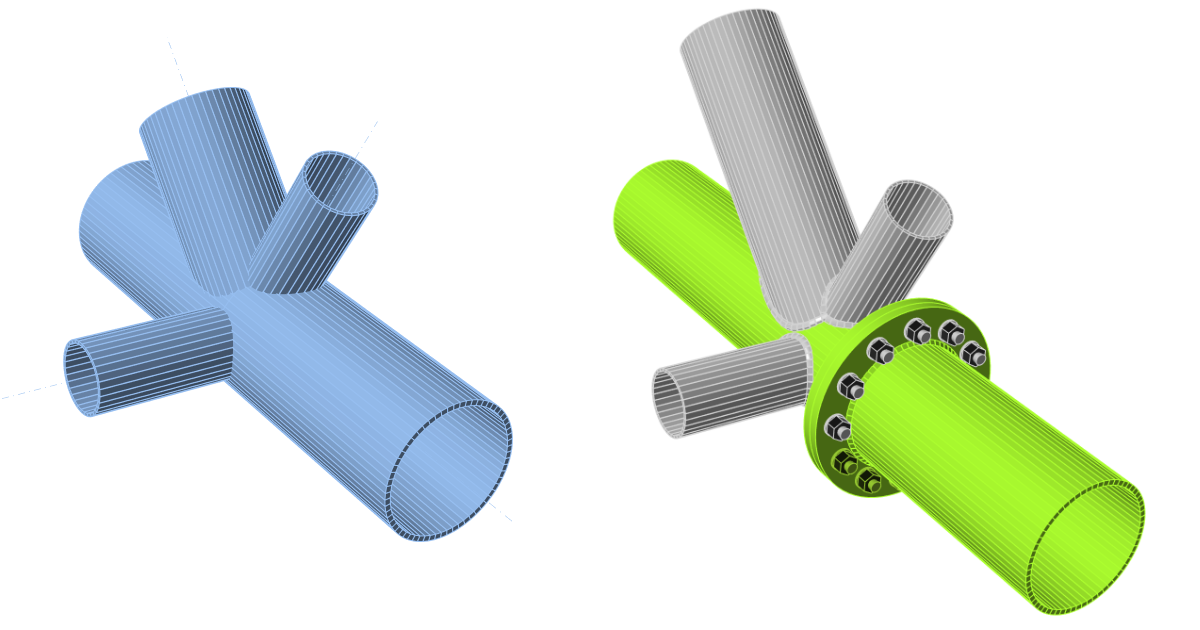
Connection design of a tubular 3D frame (EN)
1 New project
Let’s launch the IDEA StatiCa Connection application (download the newest version). Create a new project by selecting the template closest to the required design. Select the desired steel grade (S355) and the design code (EN). You can also fill in the name and description of the project. After that, press Create project.

2 Geometry
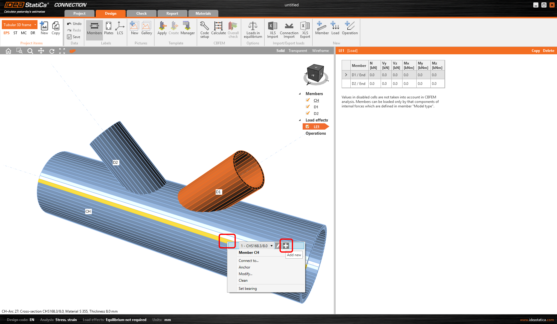
- Start with the modification of the joint geometry. Right-click on the continuous beam opens the context menu with all available actions for the beams. Use the plus button to add a new cross-section.
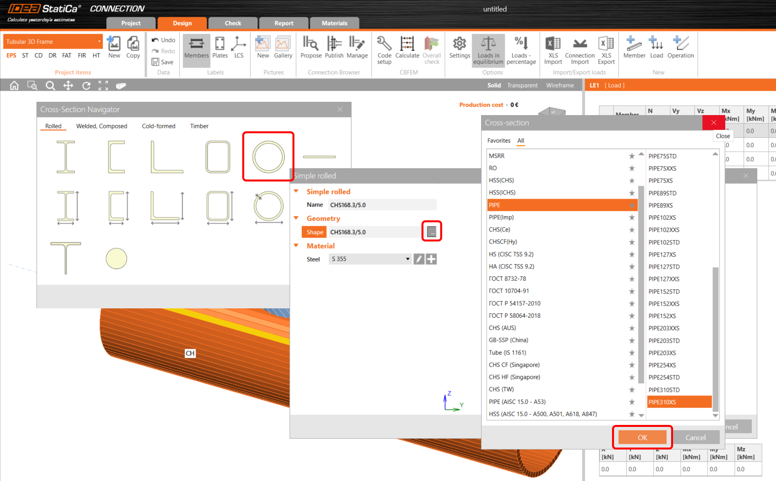
Choose the Circular hollow section profile, PIPE category, and PIPE310XS cross-section.
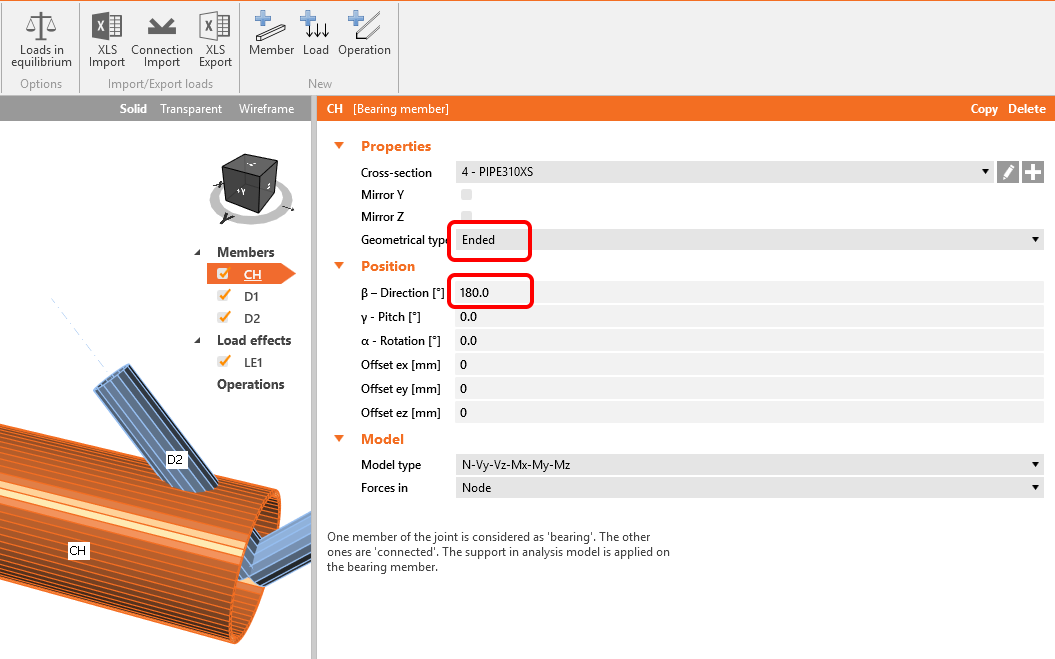
Change the member CH properties, follow the picture below.
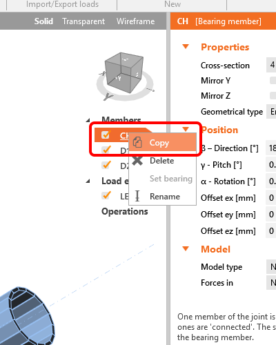
Take advantage of the prepared member and copy its properties. Click the right mouse button at the CH item on the list of the entities and select Copy command.
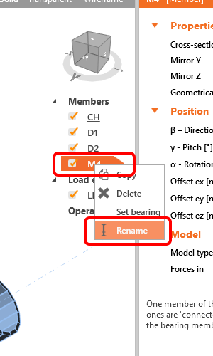
Proceed with renaming the new member, again, use the right mouse button click on the M4 item, and choose Rename from the context menu. Change the name to CH–2.
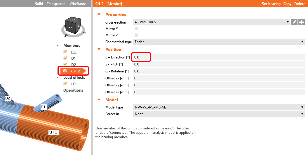
Change the properties of member CH-2 by following the picture below.
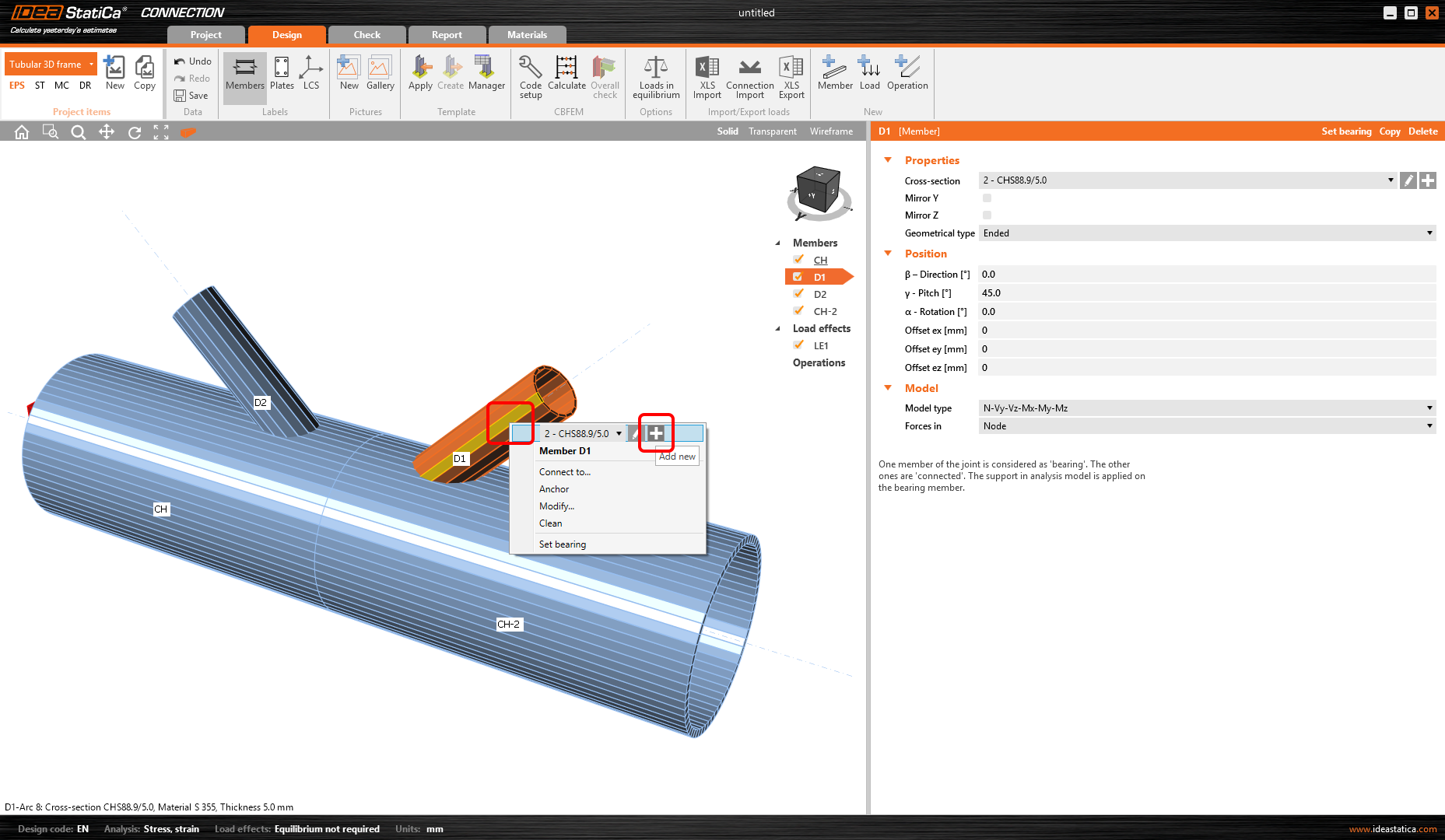
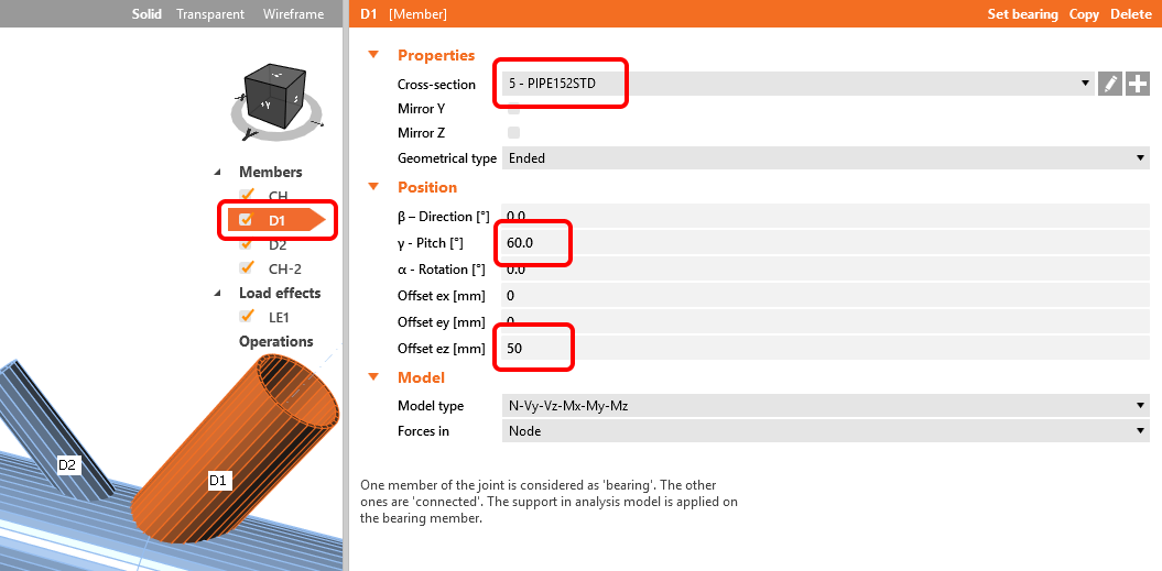
Proceed with the change of cross-section on the diagonal member. Click the right mouse button at the member in the 3D window and choose plus to add a new cross-section. Select the PIPE 152STD cross-section.
The properties of this member will be like in the picture below.
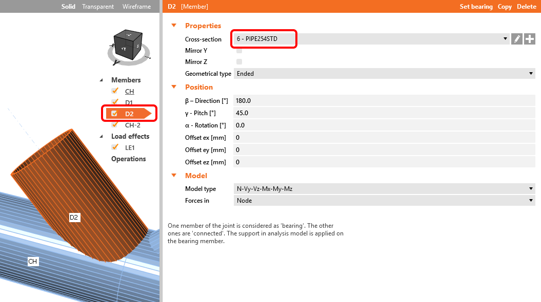
Proceed to the second diagonal member D2, change the properties following the picture below (PIPE 254STD).
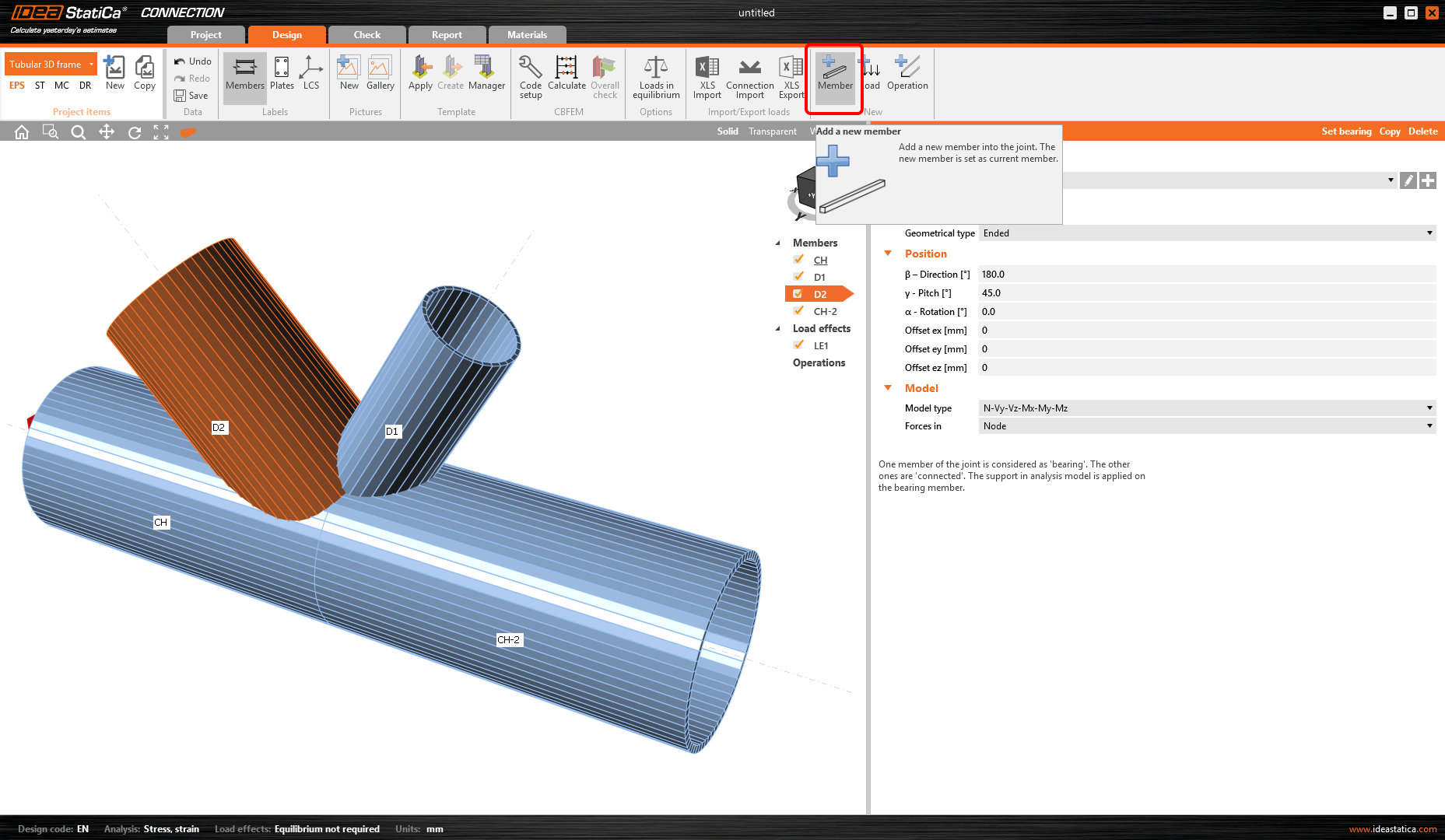
Now add another member – you can do it using the command new Member at the top ribbon.
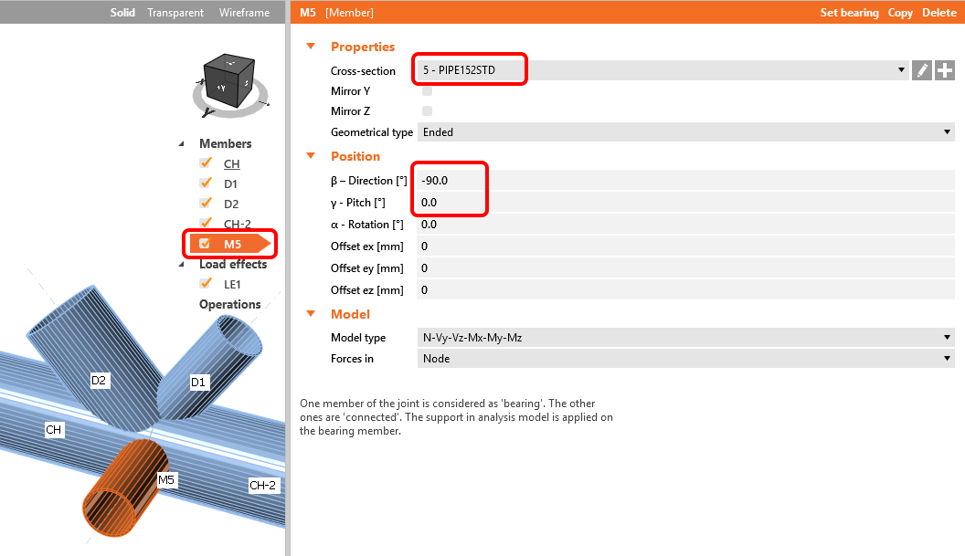
Now you can change the properties of the new member (PIPE 152STD).
3 Load effects
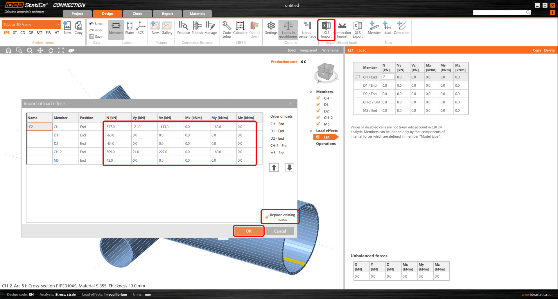
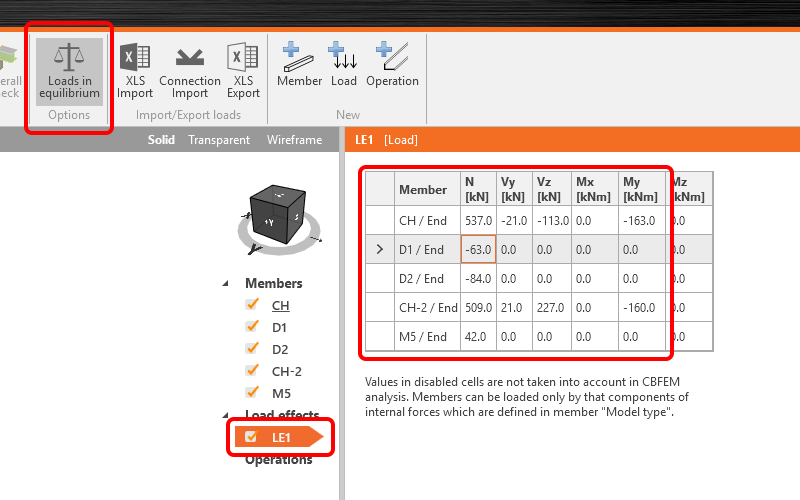
Continue with the Load effects. One load effect was automatically added. You need to input all internal forces into the table. The Loads in equilibrium option is automatically turned on. You can either insert the values manually or use the copy+paste of values from the table.
| N [kN] | Vy [kN] | Vz [kN] | Mx [kNm] | My [kNm] | Mx [kNm] |
| 537 | -21 | -113 | 0 | -163 | 0 |
| -63 | 0 | 0 | 0 | 0 | 0 |
| -84 | 0 | 0 | 0 | 0 | 0 |
| 509 | 21 | 227 | 0 | -160 | 0 |
| 42 | 0 | 0 | 0 | 0 | 0 |
4 Design
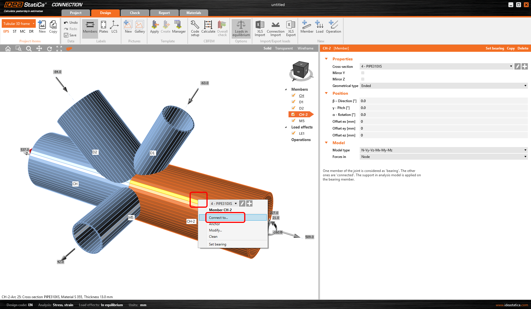
Now let's model the connection with different manufacturing operations. Start with the right-mouse-button click on the member CH-2 in the 3D scene. Choose the Connect to command from the context menu.
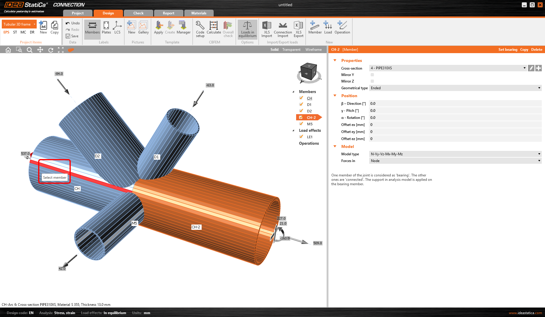
Now choose the second member to connect to (member CH).
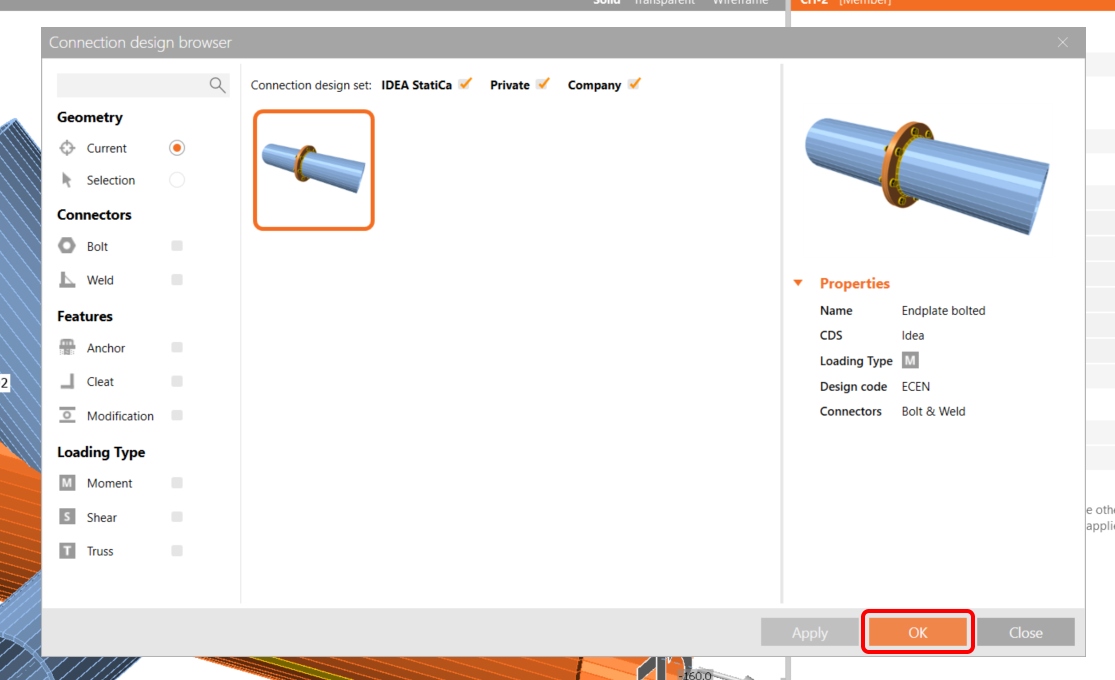
The Connection Library opens with suitable templates to choose.
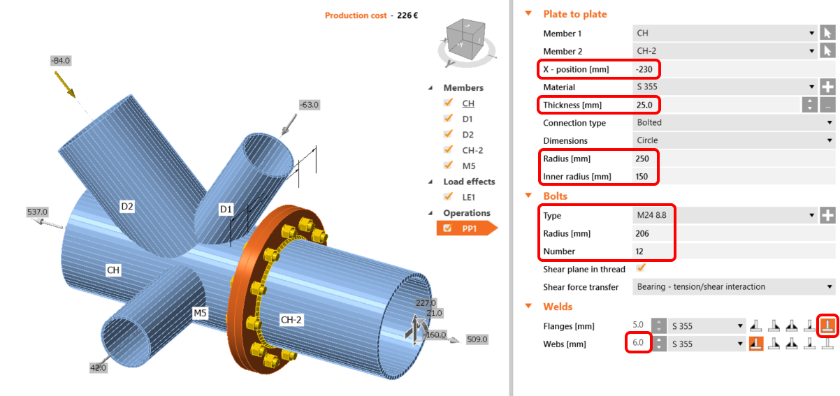
Define all necessary properties of manufacturing operation PP1. Follow the figure below.
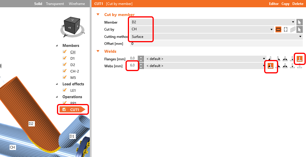
Connect the other members by the Cut from the Operation library in the top ribbon.

Change the properties of the CUT1 operation. Follow the figure below.
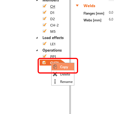
Now you can take advantage of the already defined operation and create a copy of it by the right-mouse-button click and choosing the Copy command.
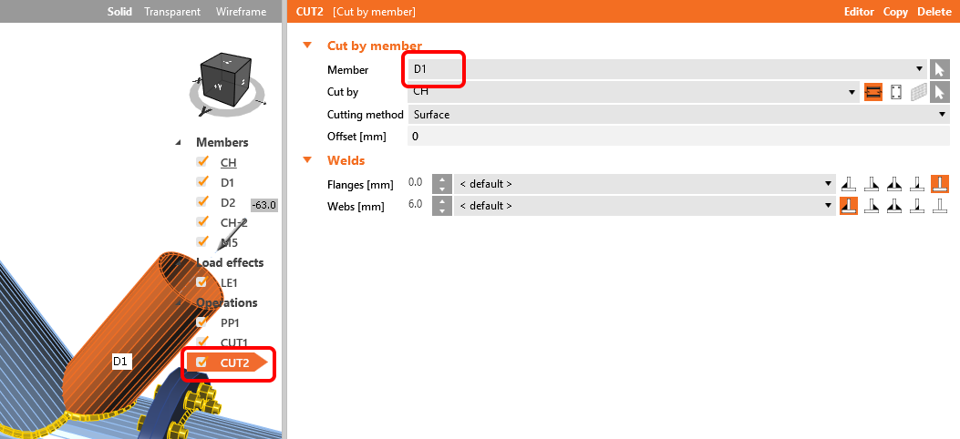
Change the properties of the CUT2 operation following the figure below.
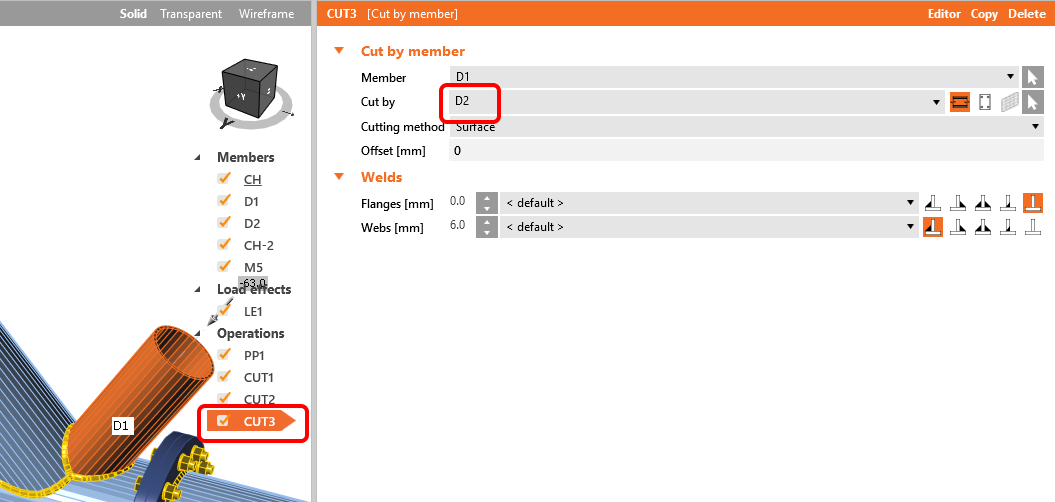
Copy the CUT2 manufacturing operation and change the properties of the CUT3 following the figure.
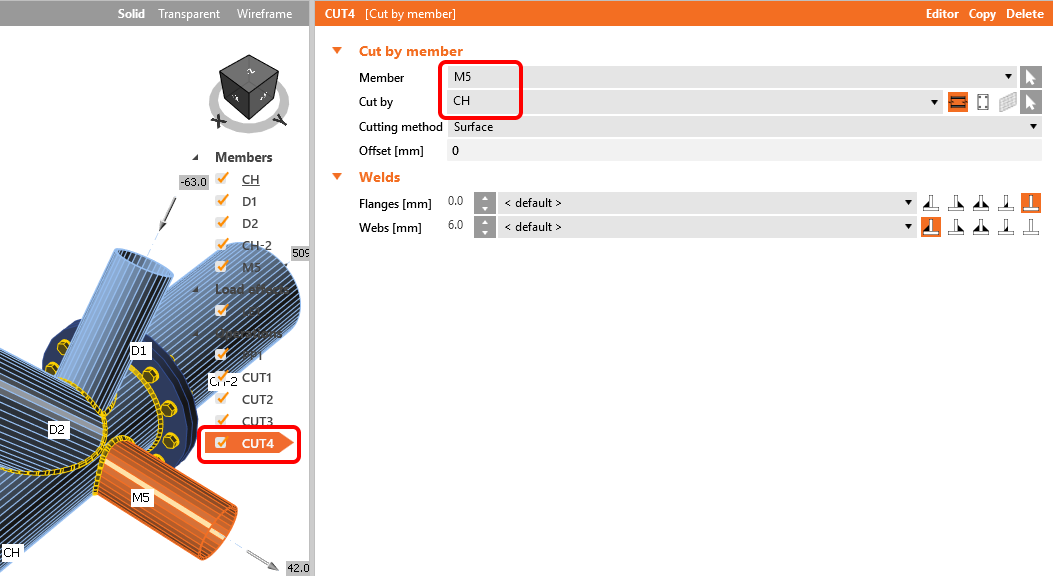
The last step in the design of the joint is the copy of the CUT3. Change the properties of the CUT4 following the figure below.
5 Calculation and Check
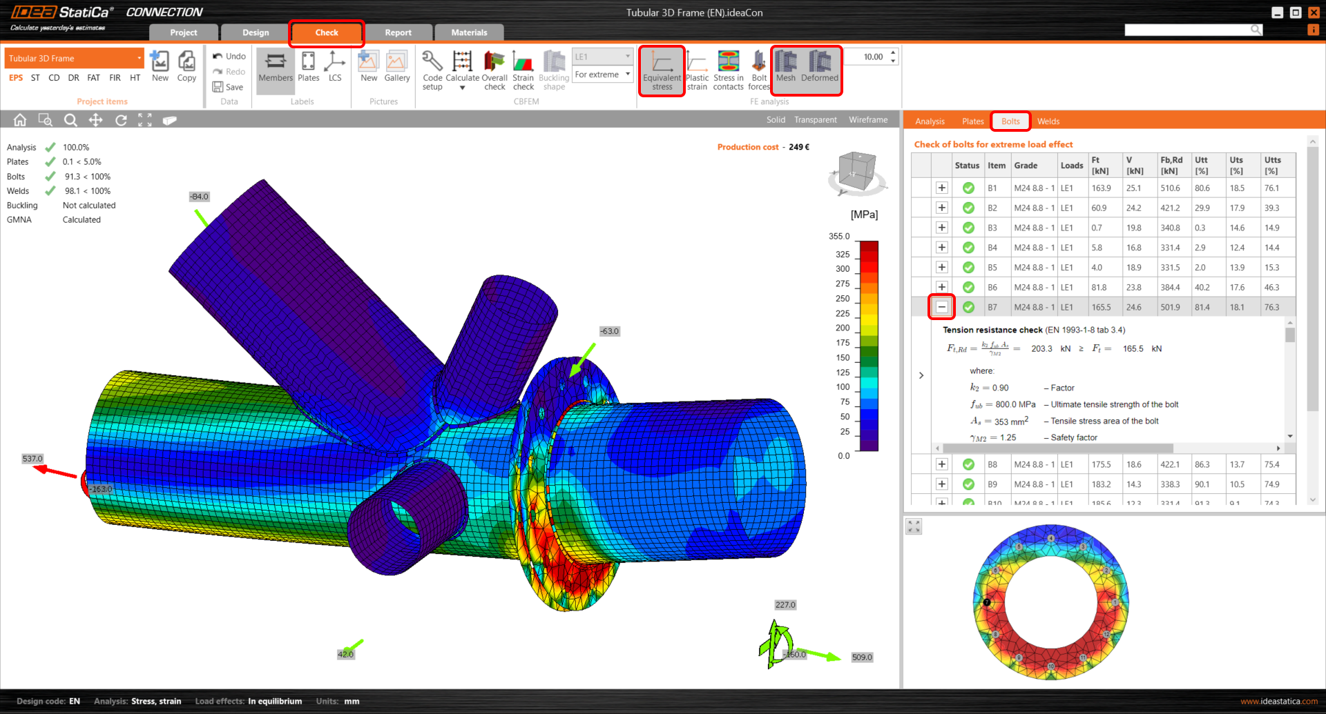
Start the analysis by clicking Calculate in the ribbon. The analysis model is automatically generated, the calculation based on CBFEM is performed, and we can see the Overall check displayed together with the basic values of check results.

Choose the Check tab and turn on the Equivalent stress, Mesh, and Deformed model view. You can browse the detailed results, e.g., for Bolts as well; to see the detailed results for the bolt B7, expand the line.
6 Report
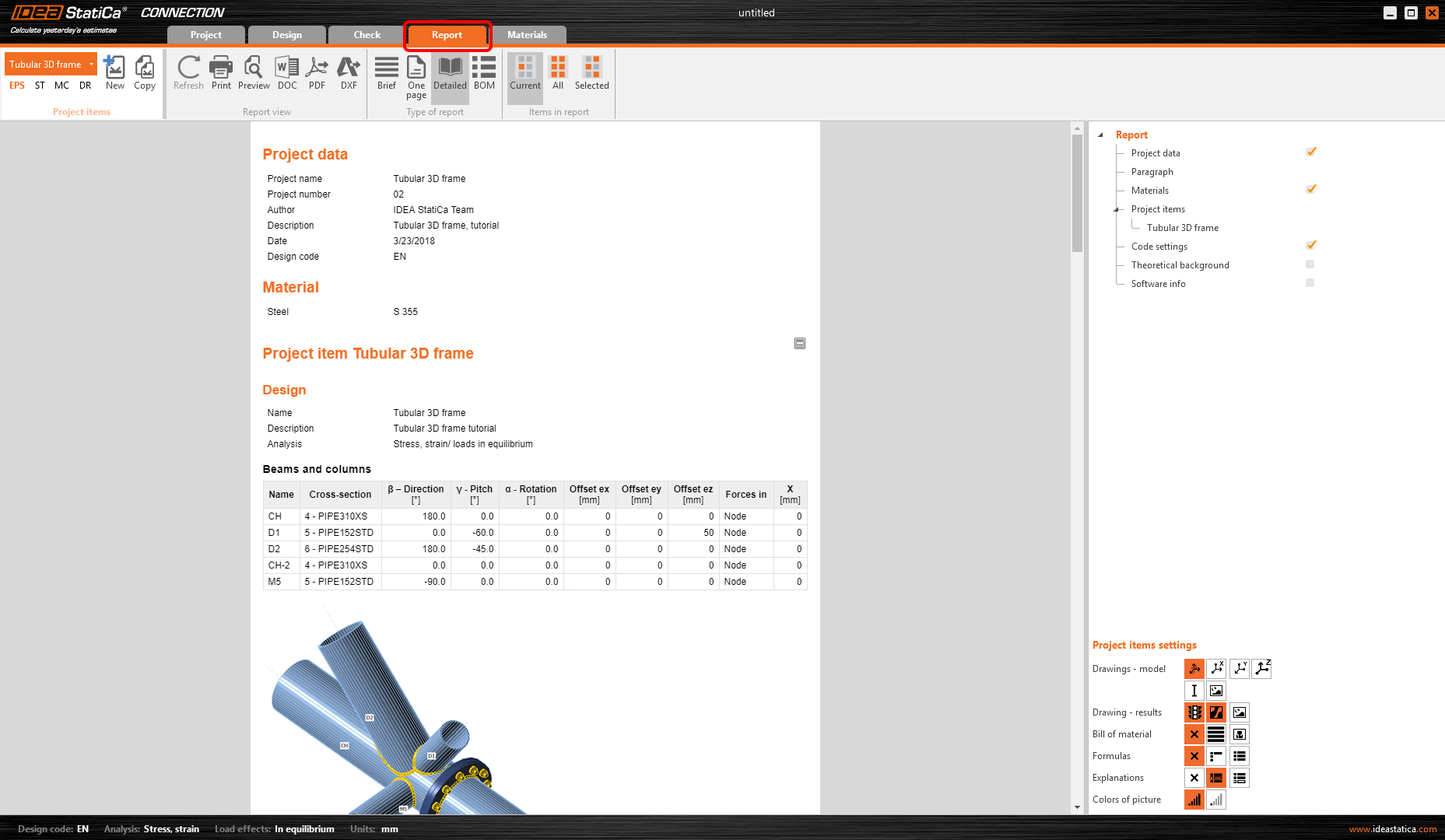
At last, go to the tab Report. IDEA StatiCa offers a fully customizable report to print out or save in an editable format.
You have designed, optimized, and code-checked a structural steel joint according to Eurocode (EN).