
Midas Civil BIM link for design of three-span post-tensioned bridge
This article is part of a series of three articles that comprehensively cover the issue of importing internal forces into IDEA StatiCa BIM from midas Civil. The other two articles are the following:
- Midas Civil BIM link – preparation of the calculation model – This article defines the principles of working with the BIM link between midas Civil and IDEA StatiCa, particularly the guidelines for properly preparing the calculation model in midas Civil.
- Midas Civil BIM link – logic of load cases and combinations postprocessing in IDEA StatiCa BIM – The article explains the logic of processing imported internal forces from midas Civil in IDEA StatiCa BIM in detail and by examples. This extension text is suitable for a detailed understanding of the issues and for solving non-standard situations during the import midas Civil – IDEA StatiCa.
The calculation model in midas Civil is available for download via the link at the end of the article. Compared to real-world practice, the model is simplified in terms of the number of load cases and combinations for the purpose of this tutorial. However, the standard operations with load cases and combinations in midas Civil are part of the prepared model so that the user has a practical example of how to prepare the calculation model in midas Civil for export.
1. Export of results from midas Civil
Open the attached model and perform the calculation. Then, you will proceed with exporting the results.
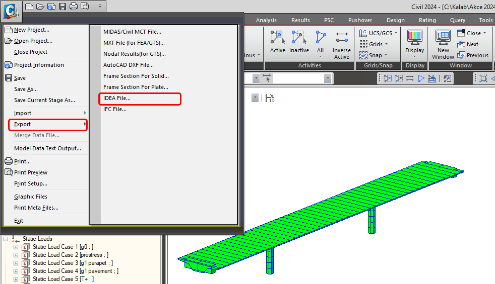
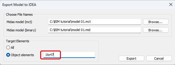
You will export only the superstructure of the bridge, elements 1 to 47.
2. Import of results to IDEA StatiCa BIM
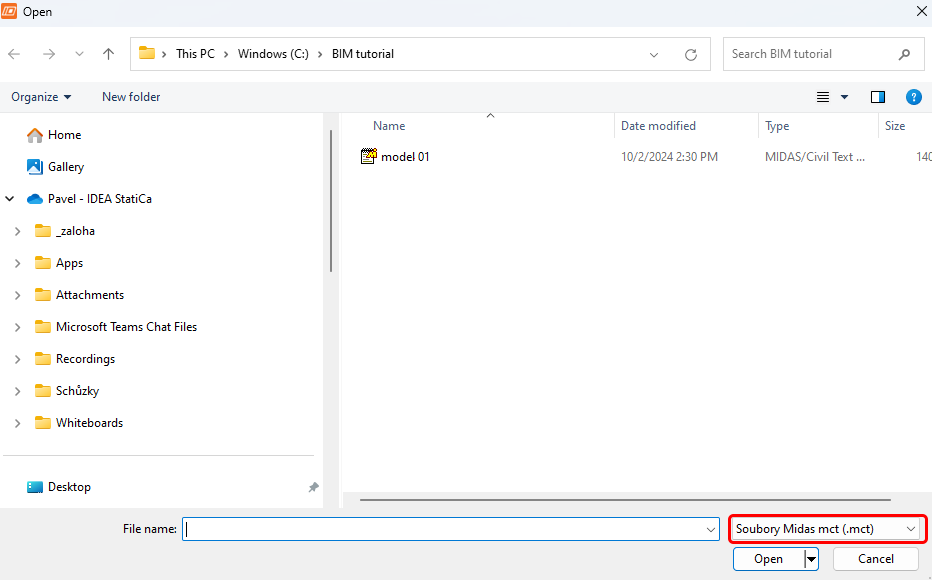
Launch the IDEA StatiCa software, go to the BIM tab (BIM app), select "Import from other programs," and choose the prepared .mct file.

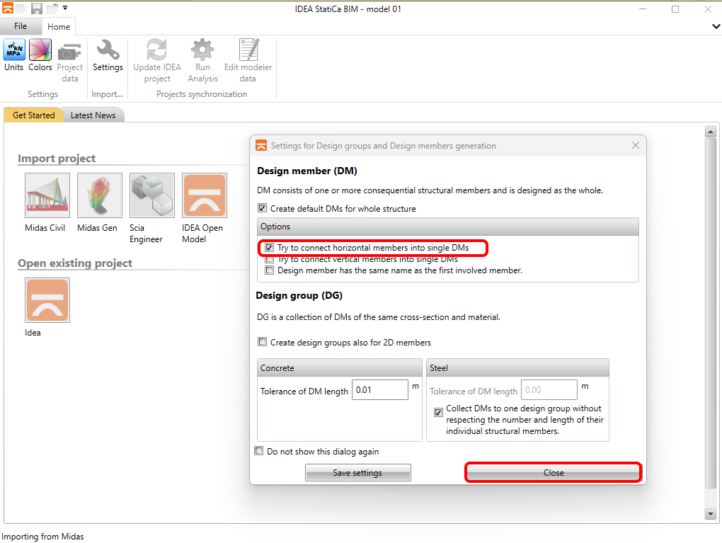
If you are importing for the first time, configure the generation of design groups and members. The BIM app will automatically combine the imported bridge superstructure into a single design member. This setting can be saved so that it will not appear the next time.
If the BIM app encounters any discrepancies during the import, it will display them in the Import Details window. In this case, this concerns the so-called "immaterial" material C35/45 used for the cross beams. Since you are not assessing them, there is no need to pay attention to this message. If it concerns the bridge superstructure, it would be necessary to check that the correct standard material from the IDEA StatiCa materials library has been assigned to the material from the midas Civil model.
The second message relates to loads due to nonlinear temperature change, which generally has two components. The first is the stress component, expressed by internal forces N-M-M provided by the midas Civil program and imported into the model. The second component is the so-called residual stress, which is self-equilibrating within a cross-section and cannot be expressed by internal force. Midas Civil calculates these internally during the stress analysis, but they are not exported, and the IDEA StatiCa BIM app does not consider them. Therefore, when evaluating the SLS checks, it is necessary to account for a margin.

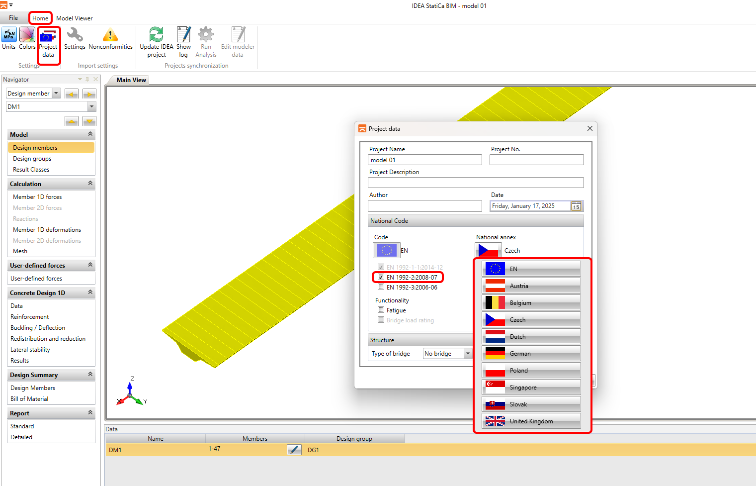
Next, you must set the calculation parameters in the Project Data tab. The first parameter is the Code, followed by the National Annex. You will not need to set the bridge type, as it will be applied when using the Load Capacity functionality, which is not covered in this tutorial.
3. Load import check
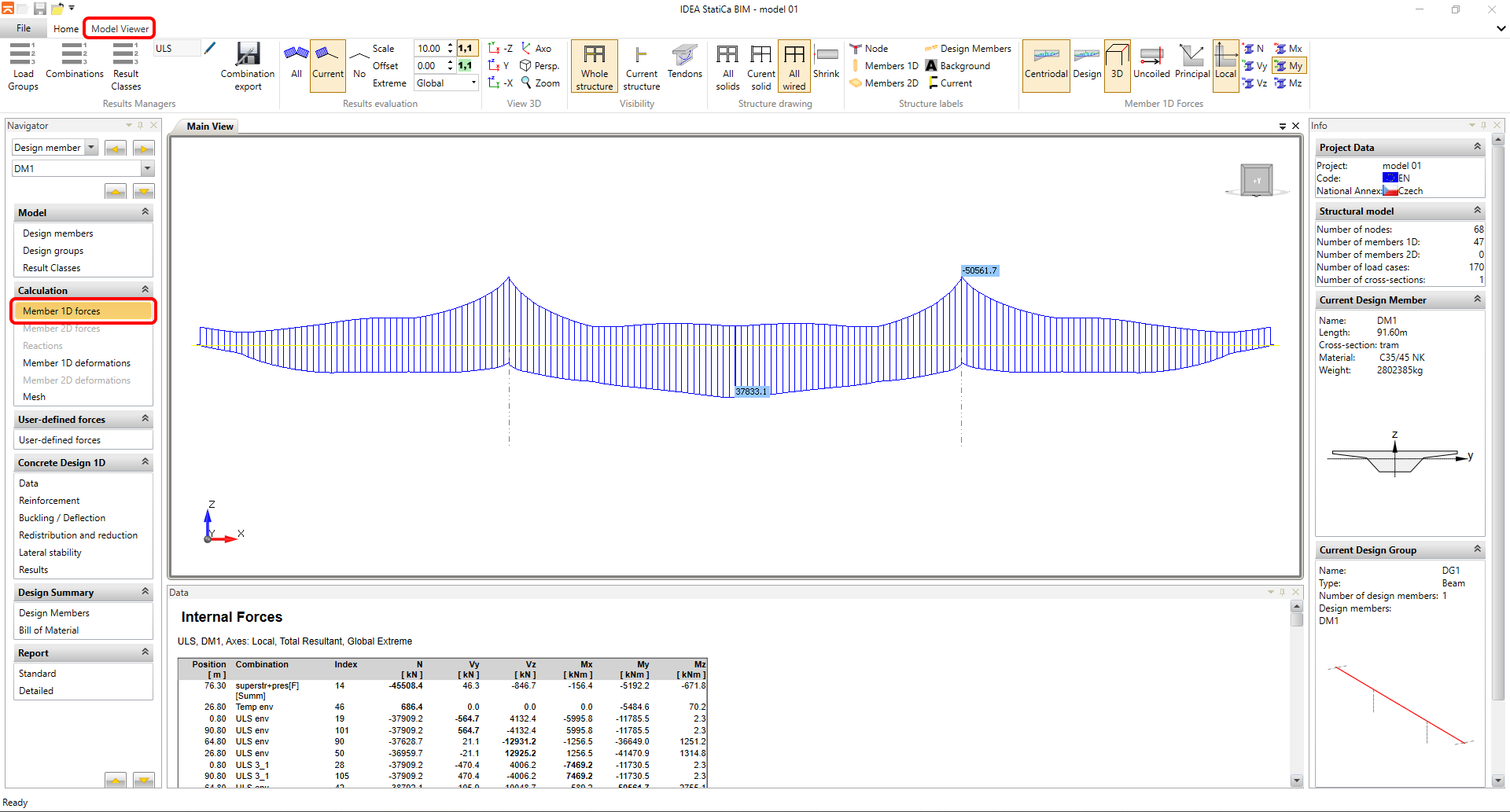
In the next step, you will check the import of load cases and their assignment to load case groups and perform a final comparison of envelopes between midas Civil and the BIM app. Switch to the Internal Forces tab for 1D members in the left navigator and go to the Model Viewer tab in the top ribbon.
You will open the Load Case Group Manager using the "Load Case Group" button. This is the most important part of the BIM app in terms of setting up the import of load cases and combinations from midas Civil. The dialog window lists all permanent (Construction Stage Analysis) and variable (PostCS Analysis) load cases imported from midas Civil. The individual cases were automatically assigned to groups based on the type set in midas Civil. For the reasons described in this article, it is always recommended to check that the groups of variable load cases are set to "exclusive" type. Therefore, you will verify that the thermal load cases have been automatically assigned to the exclusive load group.
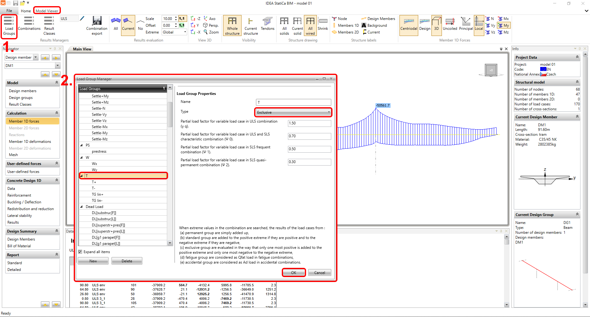
As can be seen, the condition is met, and no changes are necessary. For the group listed under the partial factors of variable loads and combination factors, you can ignore them. The factors listed in the dialog are applied for the standard envelope combinations, but the BIM app does not use these when importing forces from midas Civil. The combination factors are taken directly from midas Civil. You will perform the same check for other groups of variable load cases, and in the case of our model, this only concerns the W group.
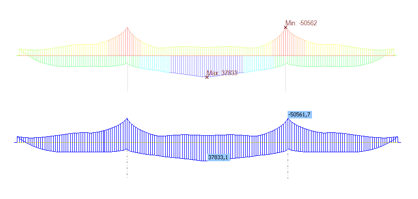
If the previously defined principles for preparing the calculation model in midas Civil have been followed and the load case groups have been checked, the envelope internal forces in midas Civil and the BIM app should match. Now, you will check the consistency of the envelope combination ULS_env. The internal force diagrams for the individual load cases and combinations are displayed in the Internal Forces for 1D Members section in the left navigator. You can switch between the displayed combinations or load cases in the top ribbon. Plot the internal force diagram for the bending moments in the summary combination ULS_env.
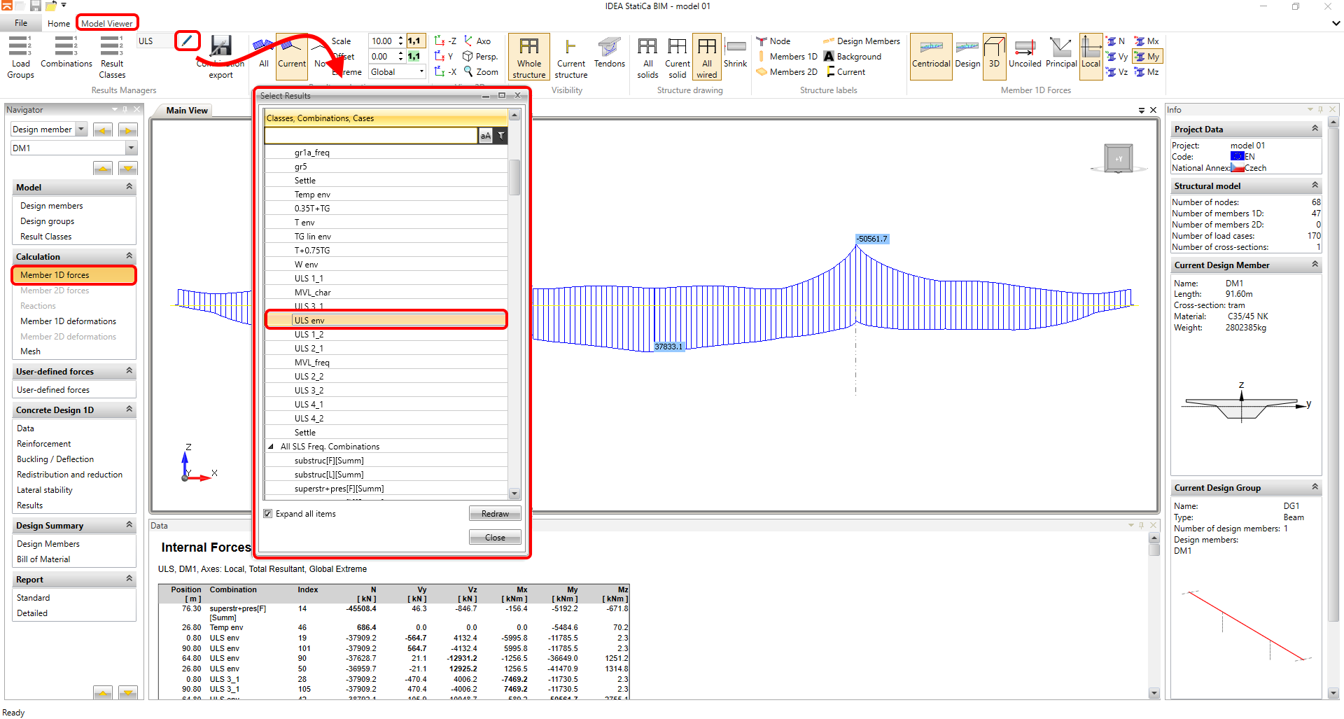
Now, you will compare the bending moment diagram My from the ULS_env combination with midas Civil.
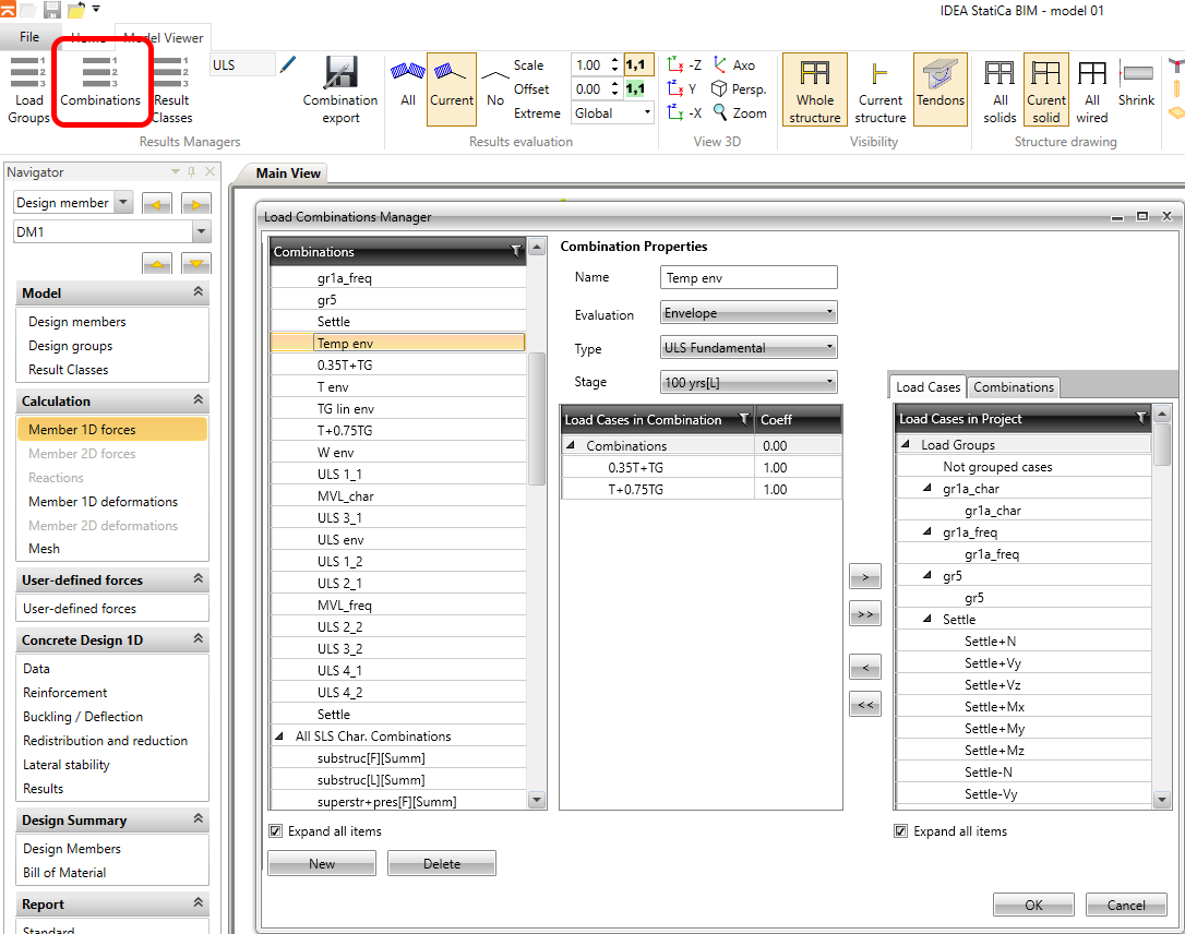
In the Combination dialog, you can view the combination rules that were imported from midas Civil. In the leftmost of the three columns, you will see the individual combinations from midas Civil, which have been automatically categorized into different groups based on the type: ULS, SLS characteristic, SLS frequent, or SLS quasi-permanent. Combinations can be edited in this dialog, or completely new combinations can be defined. You can also manually change, for example, the combination type from ULS to SLS characteristic. However, if the user fully adopts the combinations from midas Civil and uses the indicator in midas, there is no need to edit anything in this dialog, as everything is handled automatically.
4. Setting result classes
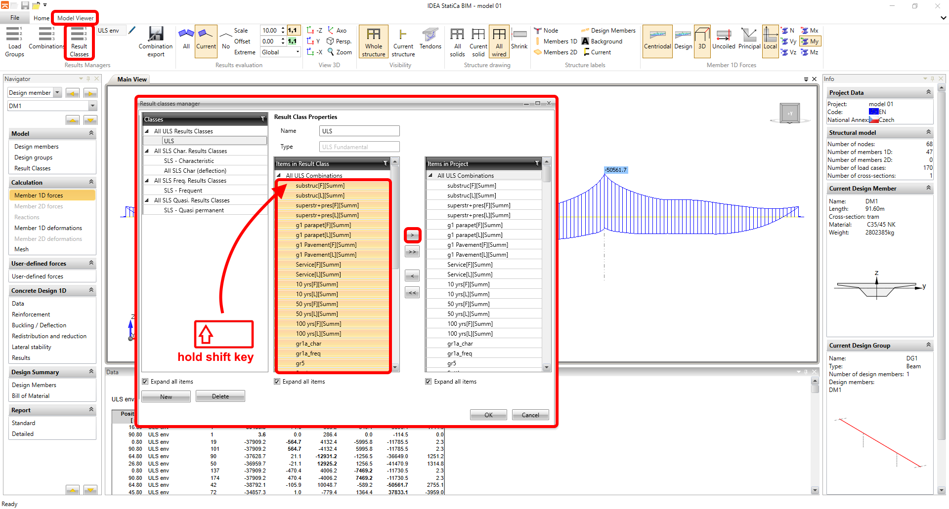
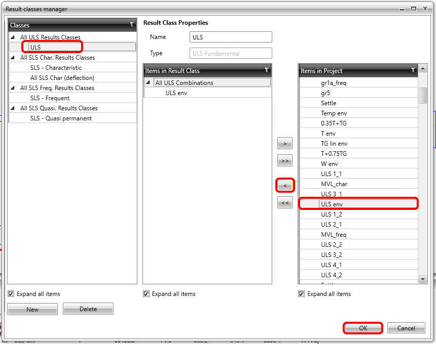
Now, you will set up the so-called result classes. All combinations from the calculation model are imported from midas Civil, which includes all auxiliary Add and Envelope combinations from lower levels. However, the cross-section checks are only performed on the final envelope envelopes. Result classes are used to define a subset of all combinations for which the cross-section checks will be carried out. Therefore, you will set up the result class for each limit state. For the result class of type ULS, you first delete all combinations and then add only the "final envelope" ULS_env to the class.
Similarly, for the result class of type SLS characteristic, you will set the combination SLS char env, the combination SLS freq env for the SLS frequent class, and SLS quasi env for the SLS quasi-permanent class. The result class SLS char (deflection) will be left empty, as deflections are not imported from midas Civil and are not evaluated using the BIM app.
5. Checks
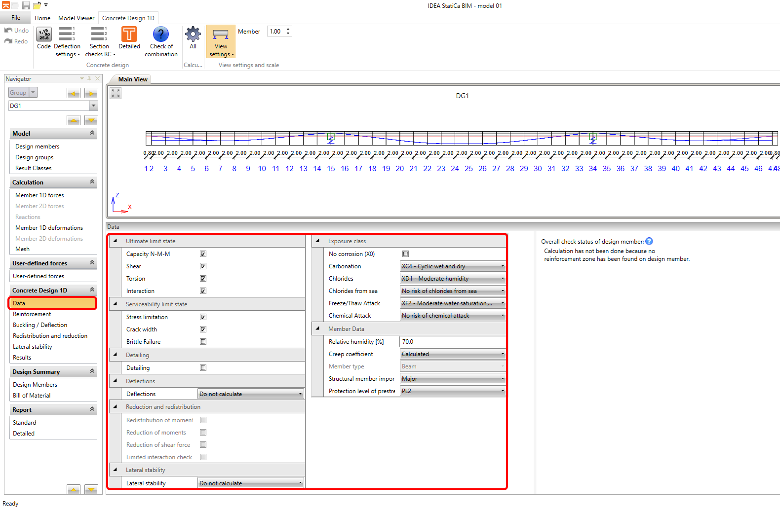
Now, you will move to the Data tab in the 1D Concrete Design group. Here, the checks to be performed on the cross-sections for assessment are set, along with the part parameters, especially the environmental exposure class. For the purposes of this tutorial, you will perform the assessment only at the center of the middle span. The settings will be configured as shown in the image below.
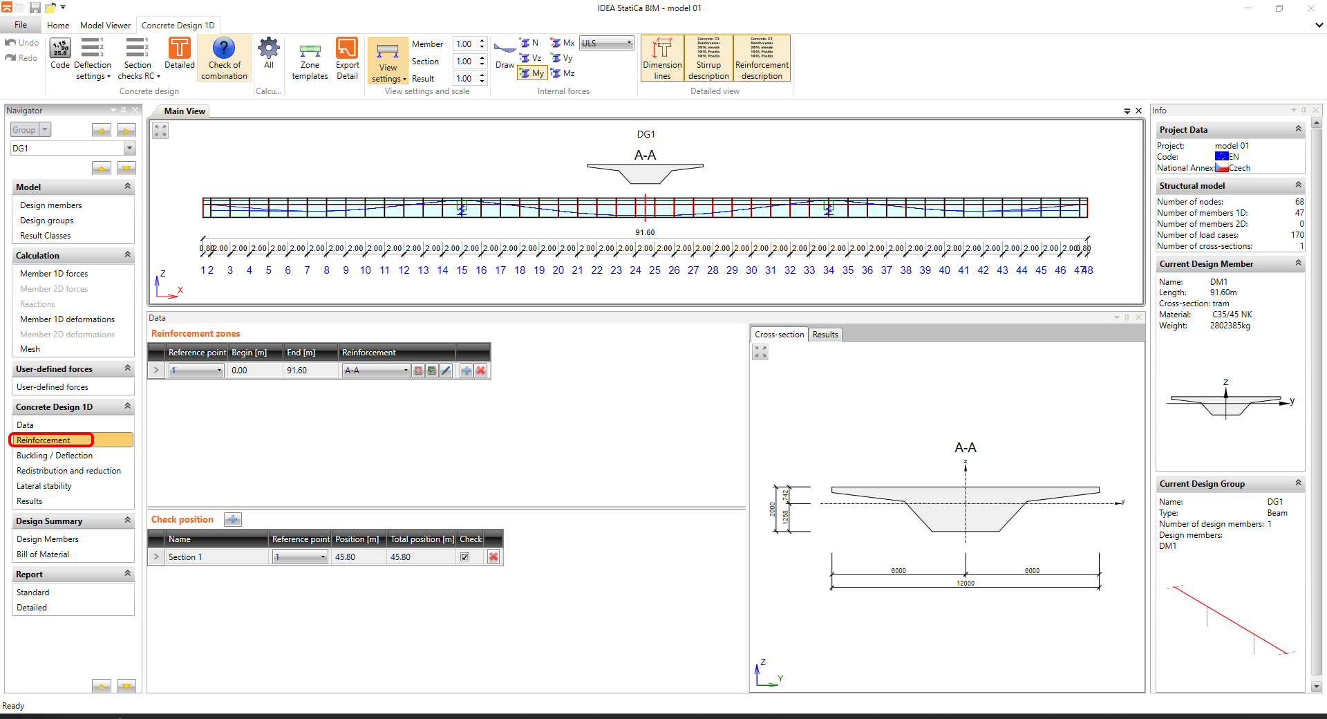
The next step is to set up the cross-sections for assessment and reinforcement. This is done in the Reinforcement tab. Individual reinforcement zones, where the same concrete reinforcement is used, are entered separately, and then individual isolated cross-sections or positions for assessment, where the evaluation will take place, are defined. It is clear that the load-bearing structure of the bridge requires assessment in several cross-sections. For the purpose of this tutorial, you will perform a detailed assessment for only one cross-section, specifically at the center of the middle span. The reinforcement zones and cross-sections that were generated automatically will not be edited.
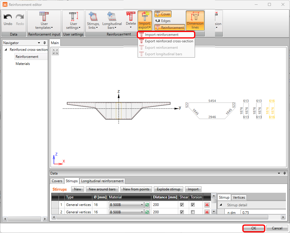
By clicking on the reinforcement button, you will open the reinforcement input dialog, which is identical to the one in the RCS app. The reinforcement input is not the subject of this tutorial, so you will use the saved reinforcement template that you have already downloaded along with the midas Civil project.
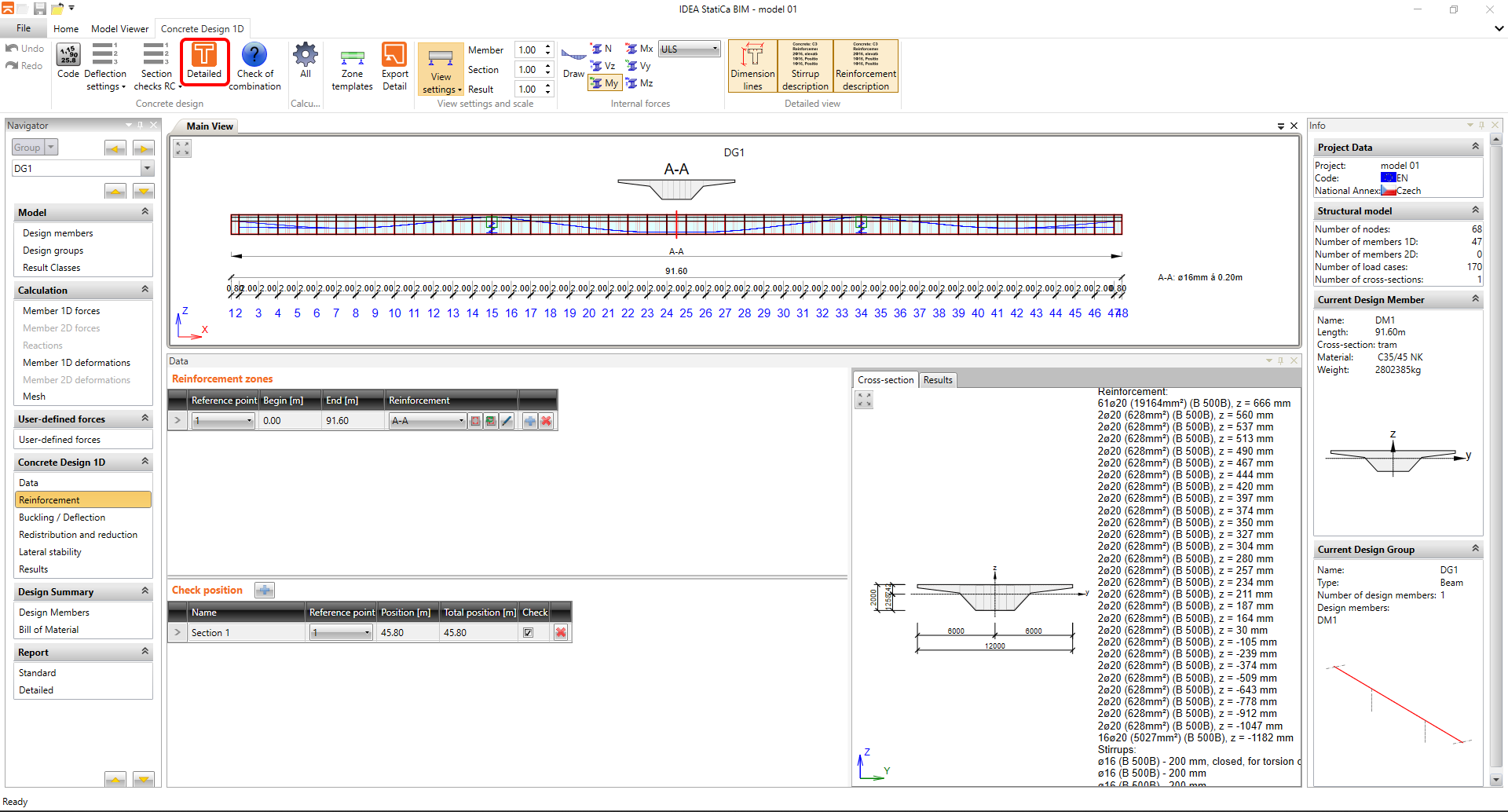
Now that the data import from midas Civil is complete and the reinforcement has been entered, you can proceed to the detailed cross-section assessment in RCS app by clicking on the "Detailed" button in the top ribbon.
The RCS app window will open, where the Construction Stages, Load Stages defining the initial cross-section state, and the prestressing effects imported from midas Civil are already fully set. The BIM app has automatically generated the individual extreme internal forces for the ULS and SLS states.
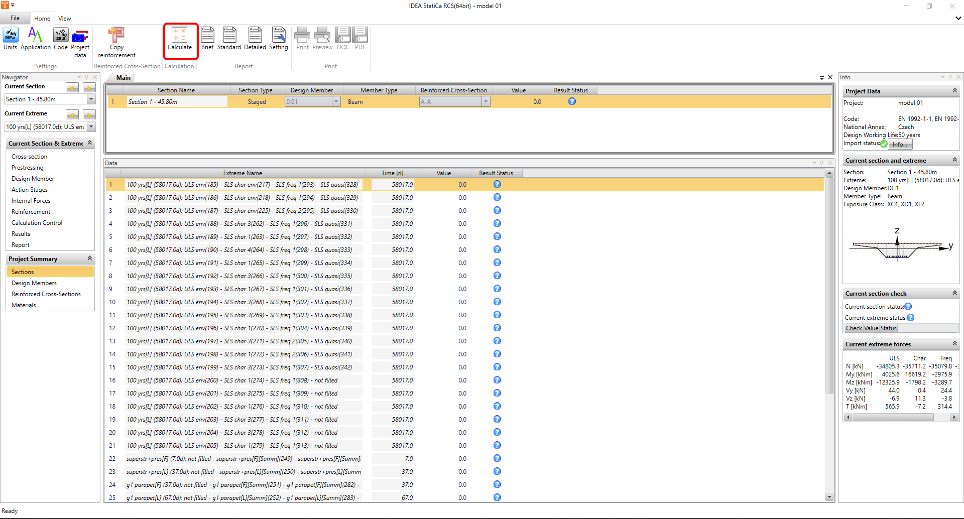
By clicking on the "Calculation" button, you will initiate the assessment calculation for the individual extremes. In our case, all the checks were satisfied.
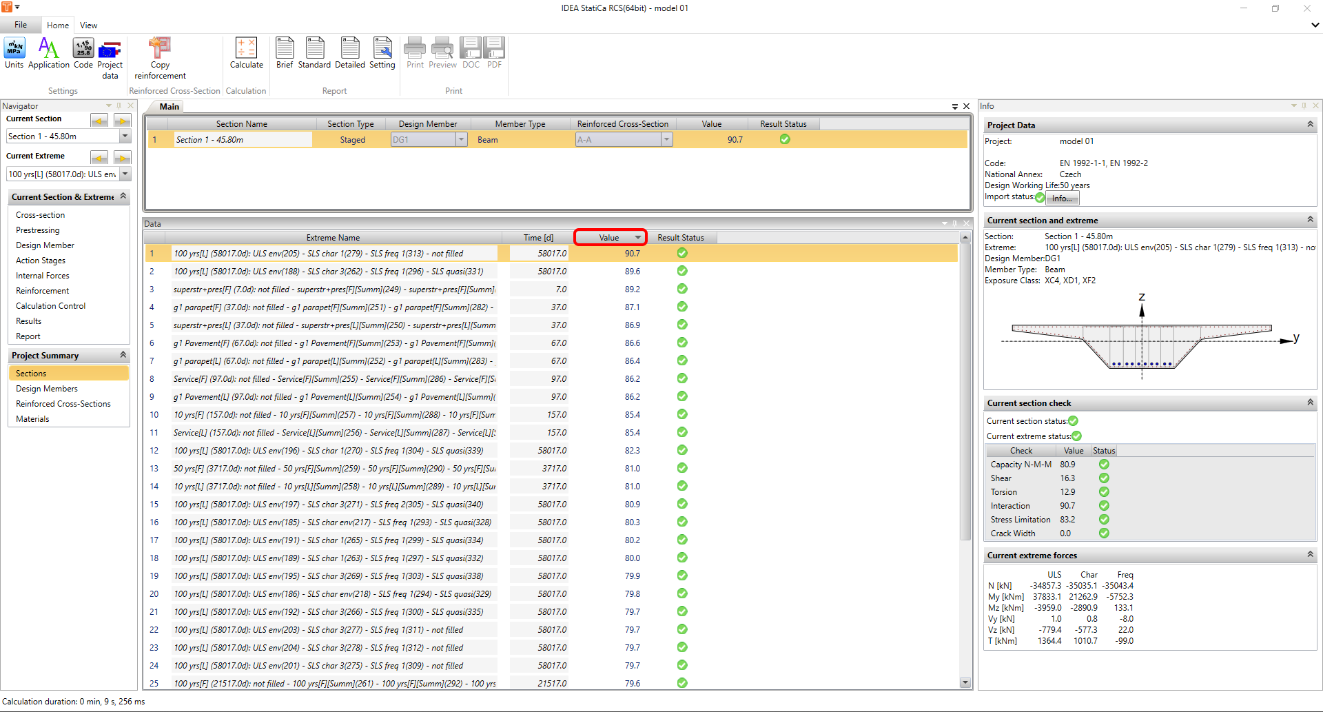
However, in RCS app, standard dimensioning operations can be performed, such as adjusting the concrete reinforcement, changing the angle of the compressive diagonal, toggling individual checks on or off, and more. The internal forces from the Load Stages and prestressing are "locked" and cannot be edited. However, you can save the RCS file to disk for further work. After reopening the file, all items will be unlocked, and the RCS file will be fully editable.