
Shear transfer through anchors, shear lugs, and friction
See the following article for a detailed description of all options and their input:
Load transferring devices
Load transferring devices contain two entities the base plate and single anchor. Let's start with the Base plate. To specify the position, a reference surface and edge must be selected. These define the origin of the coordinates from which the X and Y distances are measured. There are two shape definition options, Rectangular and Polygon.
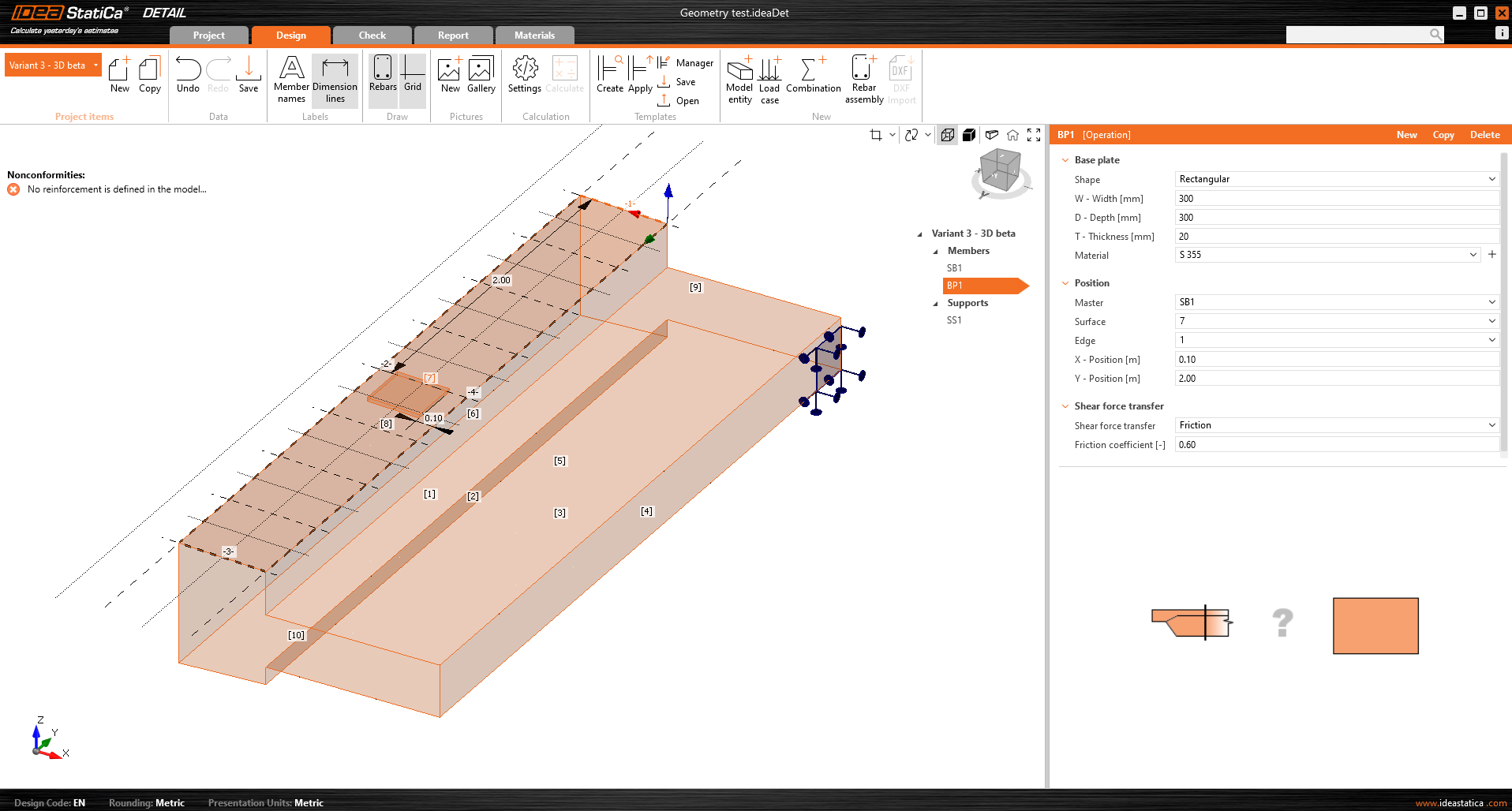
The base plate is connected to the concrete element by a contact that transfers compressive stresses and, if the user chooses, can also transmit shear stresses. There are three shear transfer mechanisms that can be selected:
- by friction
- by anchors
- by shear lug
The software does not allow you to combine these shear transfer mechanisms.
For the option by friction, the design value of the friction coefficient needs to be entered. For the option by shear lug, the steel profile, including geometry and position, needs to be inputted.
All the possible configuration of base plates can be found in the article: Base Plates Options.
The base plate can transmit either a point load or a group of forces. For a point load, the model can be loaded with six internal forces (Fx, Fy, Fz, Mx, My, and Mz) at any position on the base plate. For a group of forces, users can input the forces’ positions, intensities, and directions into a table, allowing for a general positioning on the base plate. It is important to mention that the base plate is point-loaded and doesn't have any stiffener or member welded on its upper face. Thus, for correct load distribution, it is important to use a relatively stiff base plate with relatively high thickness. Another option is to use Stub, that handless the issue with the plate stiffness.
A second load transfer device, the single anchor, can be added and interconnected with the base plate to create, for example, a base plate of the column anchored with four anchors (see the figure below). It is also possible to model separate anchors without a base plate.
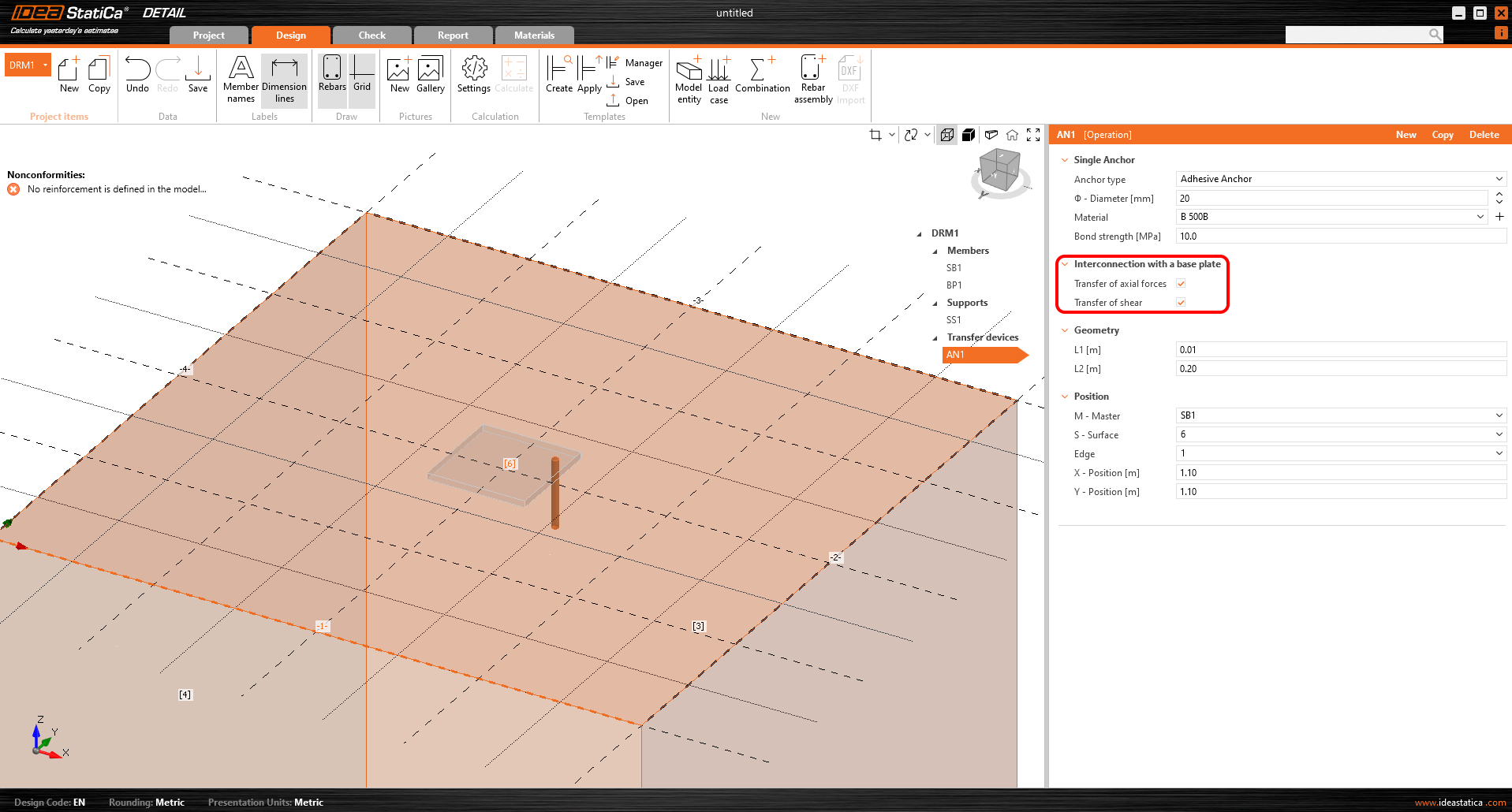
More information about the interconnection with the base plate can be found in the Theoretical background.
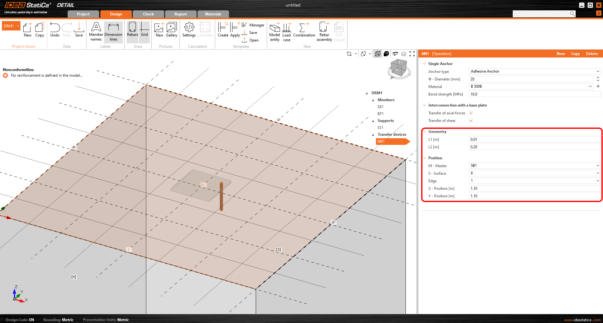
In terms of position and geometry, the anchors are referenced to the surface and edge of the block, including the determination of the relative position as with the base plate. Of course, it is possible to specify the length of the anchor in the concrete and the length above the concrete surface.
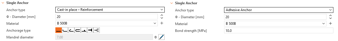
The anchors are implemented in two variants:
- Cast-in-place
- Adhesive anchors
For the Cast-in-place Reinforcement, the Bond strength is used according to EN 1992-1-1 chap. 8.4.2. In addition, it is possible to specify the Anchorage type for this type of anchor as for conventional reinforcement.
For Adhesive anchors, it is possible to directly input the bond strength, which the user can find out from the technical data sheet of the applied adhesive mortar. Note that it is necessary to input the design value of the bond strength. The following article will help you find the value.
See all anchors options in the article: Single Anchor Options
A thorough description of the behavior of the interconnection between the anchor and base plate is described in the Theoretical background.
Known limitations
Since Detail is just a tool and cannot replace engineering judgment, a safe understanding of its functions, benefits, and limitations is necessary. Read the following limitations, which must be taken into account:
- In Detail, the anchors are only checked for tensile strength. It is necessary to use Connection for shear and interaction checks.
- Only models anchored via the base plate and only Direct contact can be imported to Detail (from Connection).
For a full list of limitations with further explanation, see the article: Known limitations for 3D Detail
Released in IDEA StatiCa version 24.1