Don't waste time with SLS checks
As per Eurocode 1990, the limit states that concern:
- the functioning of the structure or structural members under normal use;
- the comfort of people;
- the appearance of the construction works;
shall be classified as serviceability limit states (SLS). This includes deformations, vibrations, and damage affecting the appearance or durability, such as, e.g. cracking.
In other words, these limit state checks are not restricted by the strength resistance of the structure’s elements, but it is more about the overall durability of the structure and also the psychological comfort of people.
Let me explain this in greater detail. Where would you feel more comfortable? In a new building with already cracked walls and bent ceilings or beams where the state could worsen in time? Or in a building with nice and smooth walls, and you can’t notice the slight deflection of the floor? I’m not even going to guess that everybody chooses the second example. And this is exactly why we should pay attention to SLS checks.
However, we all know that structural engineers' time is precious, so they want to be as efficient as possible with their designs. As a solution, we have developed new features in the IDEA StatiCa Detail app to make sure that engineers using our tools have the design and assessments done fast, economically, and safely.
Stress limitation check – not that limiting anymore
How often have you dealt with unsatisfying results for the stress limitation check? In my case, I must say many times. And I had already known in most cases that they could have been neglected because of the nature of the results.
One of the most typical issues is stress peaks - singularities usually occurring in sharp corners. Let’s take a look at what it is and why it is important not to confuse a singularity with stress concentration.
At first glance, you may remark that you don’t see the difference between those two. Nevertheless, there are distinctions, and you should always be aware of them. Because, in the end, the overall design is always up to the responsible engineer and their judgment.
So, what is a singularity, and how can structural engineers recognize it from stress concentration?
A stress singularity is a mesh point where the stress does not converge towards a specific value, i.e., that theoretically, the stress value at the singularity is infinite.
It’s typically:
- An area where the point load is applied.
- A sharp corner of the structure.
- A point restraint.
- Corners of bodies in contact.
And you can be sure it is a singularity when:
- There is a rapid change in stress in one mesh element.
- The value of the stress in one node of the mesh is higher than the limit value.
- It affects only a small structure area and doesn’t reach adjacent elements.
Back in the days when I dealt with structures with singularities, I knew that in almost all cases, they could have been neglected because of the reasons mentioned above, but there was no way to do it if I wanted to have satisfying checks in the used app. This meant I had to modify the model in various ways, so I spent a lot of time with it or possibly increase the material grade or input additional reinforcement.
And this is where the Detail app comes in with its new Limited stress check functionality.
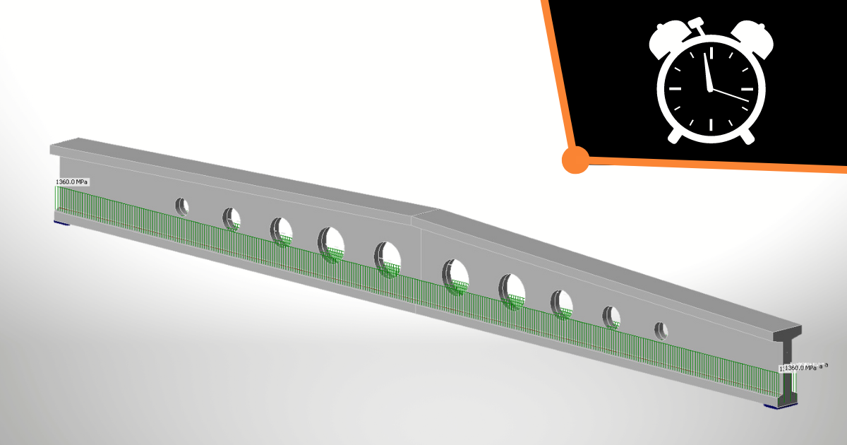
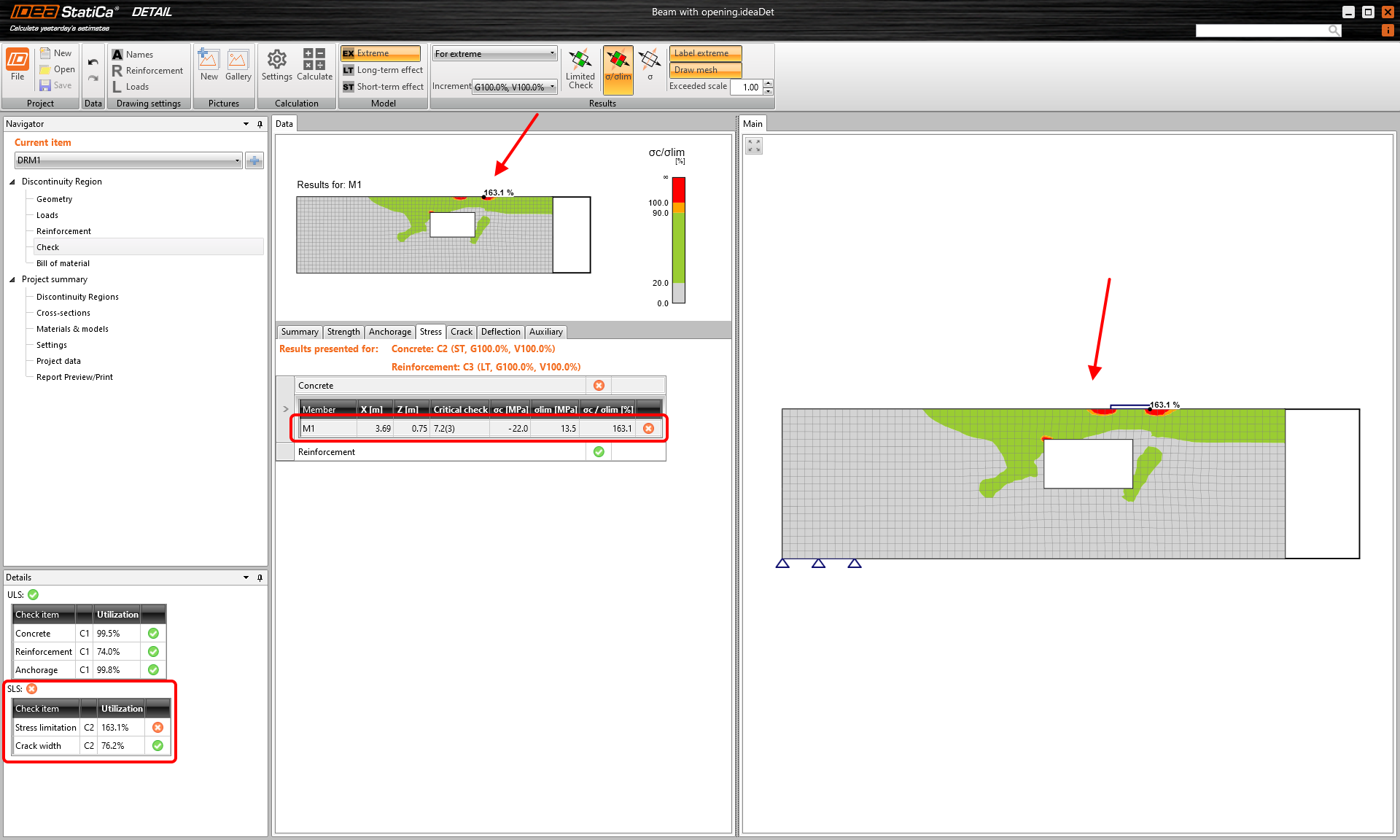
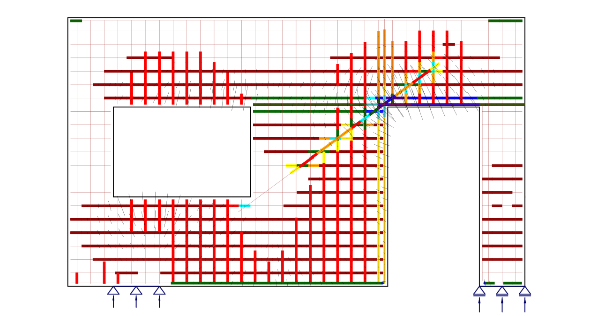
Let’s see how the feature works in a practical example. We have a beam with a trimmed end and opening. The load is a combination of a line load and a point load. After running the analysis, we can see that the stress limitation check for concrete is not OK with all the necessary information.
After closer examination, it’s clear that both situations I previously described have occurred. There is a stress concentration at the top of the beam under the point load-bearing plate and a singularity in the sharp corner of the opening.
Now is the right time to use engineering judgment! The singularity in the corner can be neglected without question in the design. But what about the small area with stress concentration? What should I do? The first thing is to turn on the mesh, which might help evaluate the impact. If it is still unclear, I can go to Settings, set the mesh to be finer, and assess again.
Nevertheless, in our case, it is visible at first sight that the stress concentration area is very small, so, from my point of view, it is acceptable to exclude it from the calculation as well.
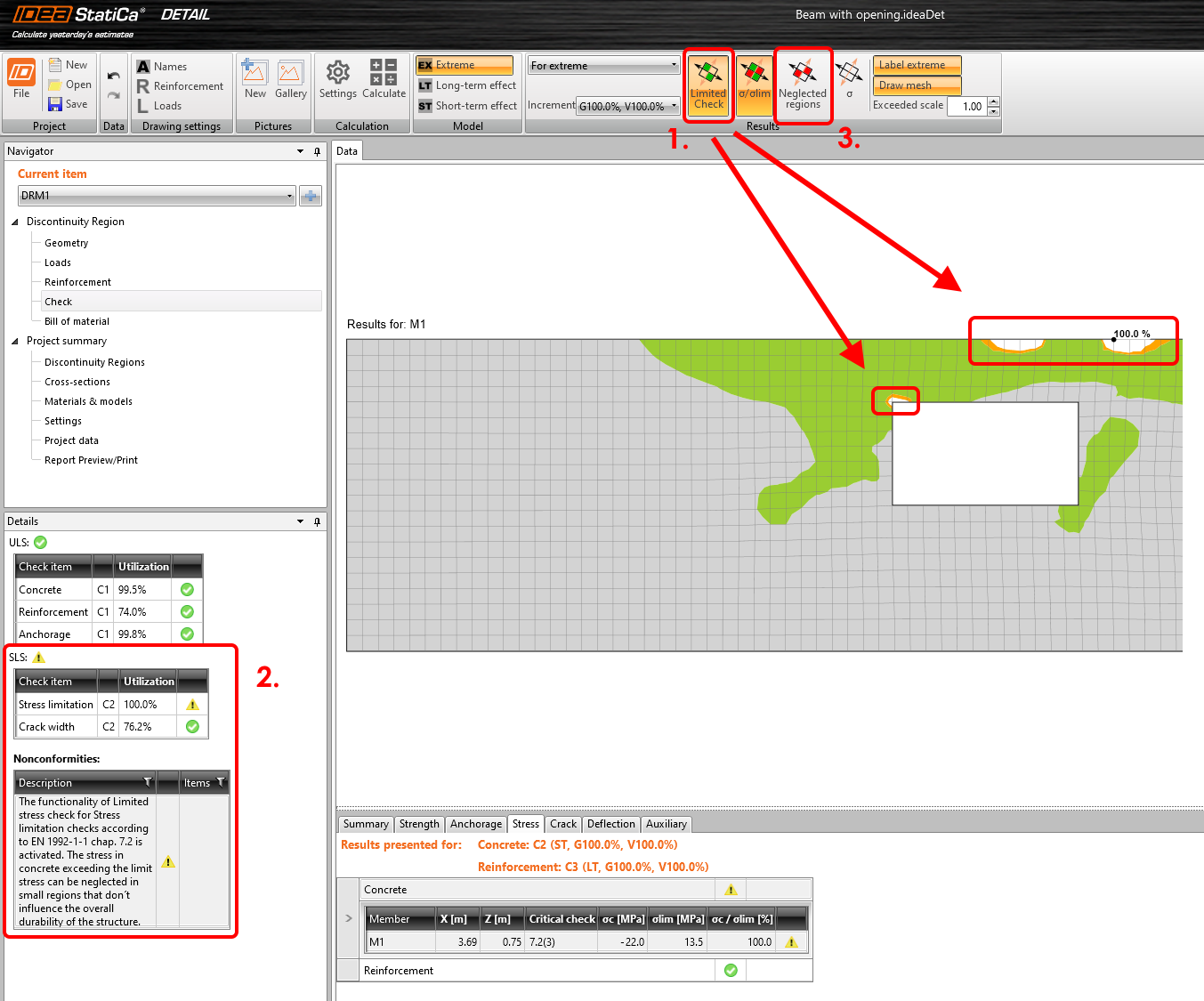
And it can be done pretty easily! For this purpose, we have developed a feature called Limited Check. The functionality allows you to neglect the unsatisfactory areas. What does this mean?
- Instead of the red areas with utilization over 100%, you see them in white, and the limit check value is 100% in the case of a stress ratio or the limit stress value in MPa.
- On top of that, in the overall check table, the red circle with a cross sign is changed to a yellow triangle with an exclamation point representing an informative matter, and a nonconformity with a thorough description appears.
- As the cherry on top, you can display only the neglected regions while the rest of the element remains in white.
All the options can be included in the report after you’re done with the modeling process and are happy with your design. So you will have bulletproof documentation to silence any doubters.
Prestressed structures in IDEA StatiCa
Every structural engineer dealing with prestressed concrete structures is aware that it is very important to pay attention to particular stages of structures’ working lives, especially the beginning and end.
It’s because no prestressing force is constant. The value is variable along the length of the prestressing tendon and, last but not least, in time. It is obvious that the correct evaluation of the precise value of the prestressing force, hence, the stresses in tendons, has a significant impact on the structure’s behavior.
The changes in the prestressing force (a decrease of the prestressing force might not necessarily appear!) are caused by many factors and are referred to as prestressing losses. Yes, I used the plural correctly. The prestressing losses are distinguished as:
- Short-term losses
- Long-term losses
Short-term losses
Short-term losses usually happen during the manufacturing process. Short-term loss can be caused by, e.g., friction, a slip in the anchorage set, immediate elastic strain in concrete, relaxation of the tendons, etc.
Long-term losses
Long-term losses occur after the application of the prestressing and can affect the structure during its whole working life. The cause of the long-term losses can be considered – creep, shrinkage, long-term relaxation, and elastic strain in concrete caused by the application of a variable load.
Not an easy task. Or is it?
Considering all of this (which is a must in the design!) may lead to having several combinations taking into account various prestressing coefficients.
Here IDEA StatiCa Detail enters the spotlight for the second time. Thanks to new functionality called Long-term losses for SLS check, you don’t need to have a bunch of combinations and spend hours with your model while stressing if you haven't forgotten something.
All you need to do in the Detail app is to set one combination, and you are able to cover short-term and long-term effects for both pre-tensioned and post-tensioned tendons.
Are you pumped to learn how it works? Let’s find out!
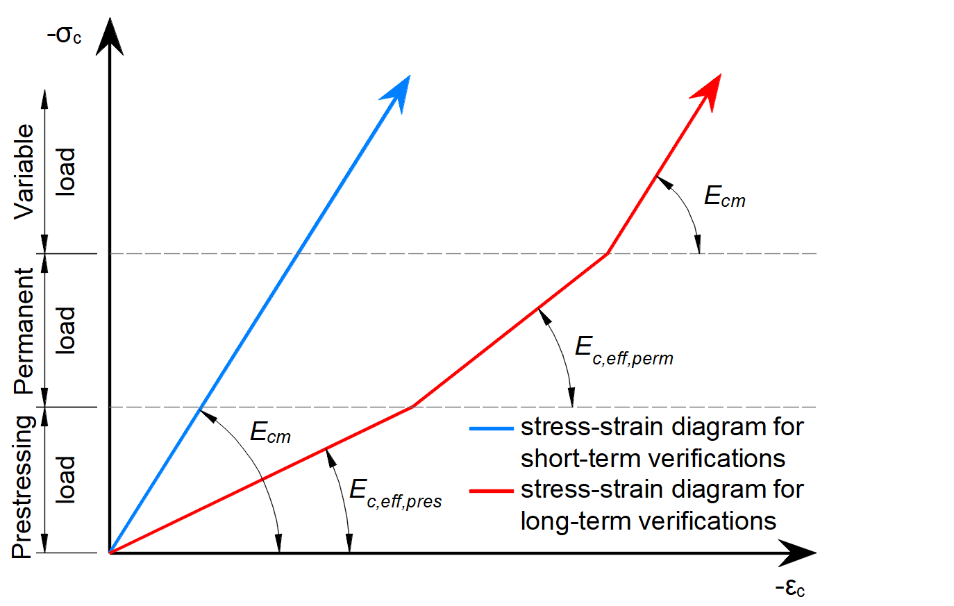
It’s important to for knowing the stress limitation check and getting the results for short-term and long-term effects in the Detail application, we use an infinite linear stress-strain diagram.
We distinguish two branches. One for short-term effects using modulus of elasticity Ecm. And the other one is for long-term effects, where the stress in tendons is reduced in increments for prestressing and permanent load by the defined value of long-term losses. The increment of variable load considers Ecm.
How to set the value of long-term losses correctly? We may provide you with some default settings; however, it is again up to structural engineers which value they will eventually use for the calculation.
Please be aware that the value differs for pre-stressed tendons and post-stressed tendons. It is because of the exact time for which you ought to set the loss value. Check the Implementation of long-term losses in Detail article, where you can find a more detailed description of the topic and, more importantly, what is the proper time for setting the long-term losses estimation to the calculation.
If you are interested in more new features of IDEA StatiCa 23.0 (maybe not only for concrete but steel or BIM links as well), visit our Release notes page.
IDEA StatiCa Detail is a great tool to solve your concrete details and other discontinuity regions. Find out more about its possibilities in our Support Center, where you can also learn how to use it in many tutorials, see our product engineers in action in one of our webinars or download a sample project.
If you are starting with the software or just want to improve your skills, check out our self-paced learning Campus courses and select the one that suits your needs the best.
For those interested even more in theory and the CSFM method behind the Detail application, go to the Theoretical background for IDEA StatiCa Detail, and go wild with studying.


