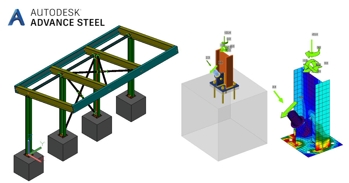
Advance Steel BIM link for steel connection design (EN)
Come attivare il collegamento
- Scaricare e installare l'ultima versione di IDEA StatiCa.
- Assicurarsi di utilizzare una versione supportata della propria soluzione FEA/BIM.
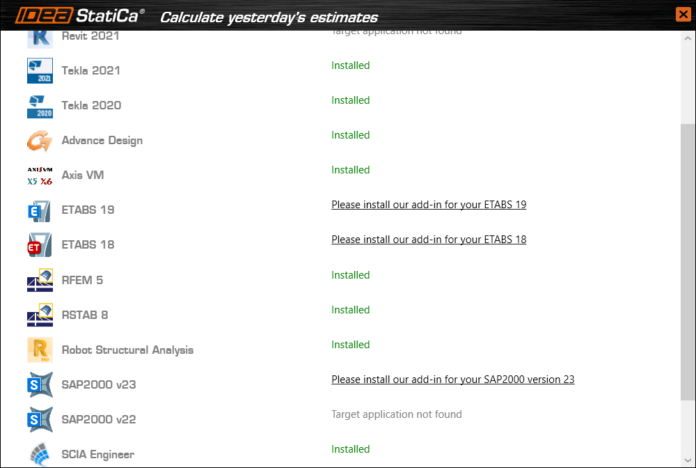
IDEA StatiCa integra i collegamenti BIM nelle soluzioni FEA/BIM durante la sua installazione. È possibile controllare lo stato e attivare altri collegamenti BIM per i software installati successivamente nel programma di installazione dei collegamenti BIM.
Si noti che alcune soluzioni FEA richiedono ulteriori passaggi per attivare completamente il loro collegamento BIM a IDEA StatiCa.
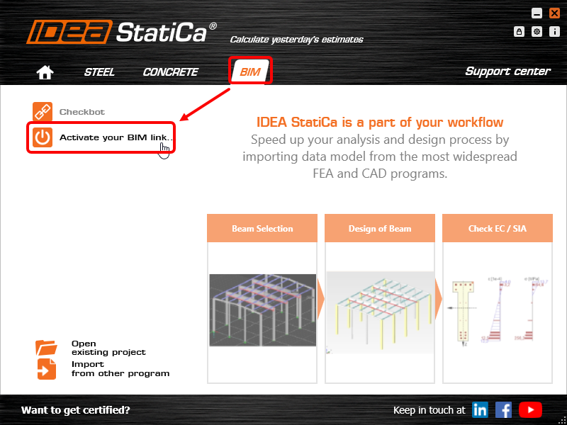
Apri IDEA StatiCa e naviga nella scheda BIM. Clicca su Attiva il tuo collegamento BIM... (Activate your BIM link...).
Potrebbe apparire la notifica "Vuoi consentire a questa applicazione di apportare modifiche al tuo dispositivo?"; in tal caso, confermare con il pulsante Sì.
Installare il collegamento BIM per il software selezionato (se trovato). La schermata indica anche lo stato di altri collegamenti BIM eventualmente già installati (Intalled).
Download the attached project and open it in Advance Steel.
The BIM link is automatically integrated. You can find it in the top ribbon under IDEA StatiCa -> Checkbot. This will open the Checkbot application.
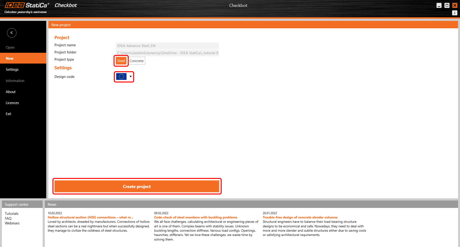
Select the New option with project type Steel and design code EN. Then select Create project.
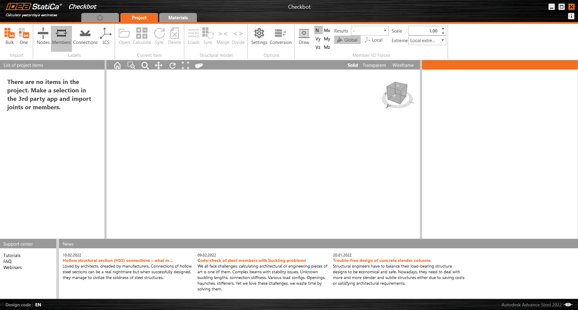
The new Checkbot project is ready to import connections from Advance Steel.
Import
There are two options of the import of the model into the Checkbot:
I. To take a larger part of the structure into Checkbot, select Bulk. (Used in this tutorial.)
This will import all of the selected parts of the structure into Checkbot - with the same coordinates, orientations, and section sizes as per the BIM model. The joint center is created automatically by the software according to the members' intersection. We recommend not importing all of the connections at the same time but building up the connections incrementally.
II. Alternatively, you can export a single node using the One button in the top ribbon of Checkbot.
Unselect everything in the structure of your BIM model and press One. Then:
- In the BIM model, select the node representing the center of the connection and confirm it with the spacebar or right mouse button or enter key.
- Now, select the structural members, such as beams and columns. The order of selected members will define the order of members in the Connection model. Confirm as in the step 1.
- Select all other connection entities such as bolts, plates, etc. and again confirm.
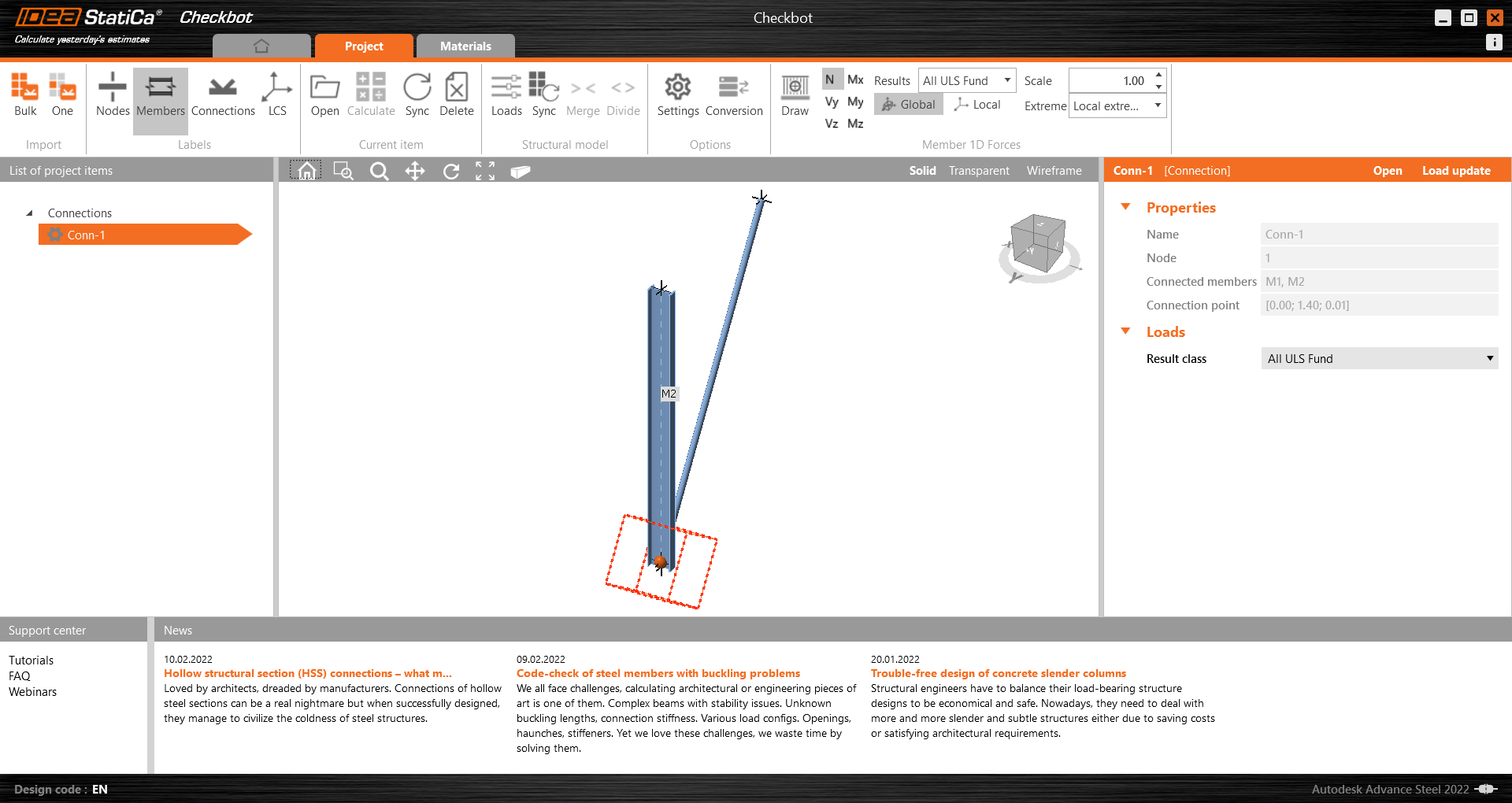
The connection will be taken to the Checkbot now.
Choose between these two ways (Bulk or One) of import. Both of them successfully import the structure.
In Advance Steel, select one of the inside columns with bracing making sure you also select all of the connection objects.
A notification "Do you want to import also recommended welds?" may appear. Since we have all welds created in the BIM model, select the No button.
Please note that your node and member numbering might be different.
Please note the 3D workspace is designed to show an overview of the imported structure and not a detailed view of the actual connections. For more information on Checkbot see here.
Geometry
In the list of project items under Connections and with a connection highlighted in Checkbot you can either right-mouse click and select Open or click the ribbon command Open to start designing, code-checking, and reporting.
The settings of members are taken from the original BIM application. You can, however, change the section size of any member on the main Checkbot screen but this will break the link with the BIM application in this session unless it's synchronized again.
The imported connection is opened in the IDEA StatiCa Connection application.
Load effects
Download the attached Excel sheet with load effects and open it.
Select the values of the internal forces in the table and copy them (Ctrl + C).
Then in IDEA StatiCa Connection, select the XLS Import button in the top ribbon.
With a left-click, select the first cell and paste (Ctrl + V) the values of internal forces.
Please be aware you need to have the same order of rows and columns in the Excel table as in the Load effects table in the IDEA StatiCa Connection application. If the rows or columns are switched, you will get the incorrect input of internal forces on members.
Design
We are going to be using a single bolt connection for the diagonal brace. For this type of connection, we must also change the Model type of the brace member to N-Vy-Vz. Select the brace in the list of Members and modify the Model type in the drop-down list.
Go to Code setup in the top ribbon and unselect the Cracked concrete option.
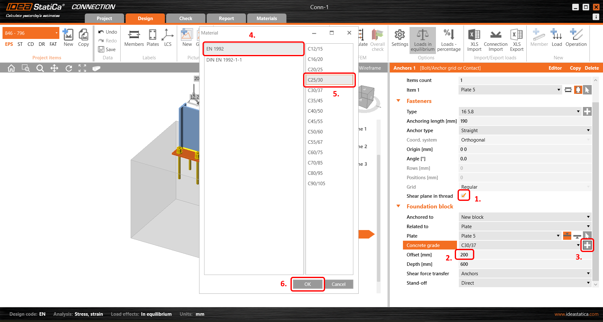
Adjust the properties of anchors and concrete block. Select the Shear plane in thread option. Set the value of the Offset to 200 mm. Change the Concrete grade to C25/30.
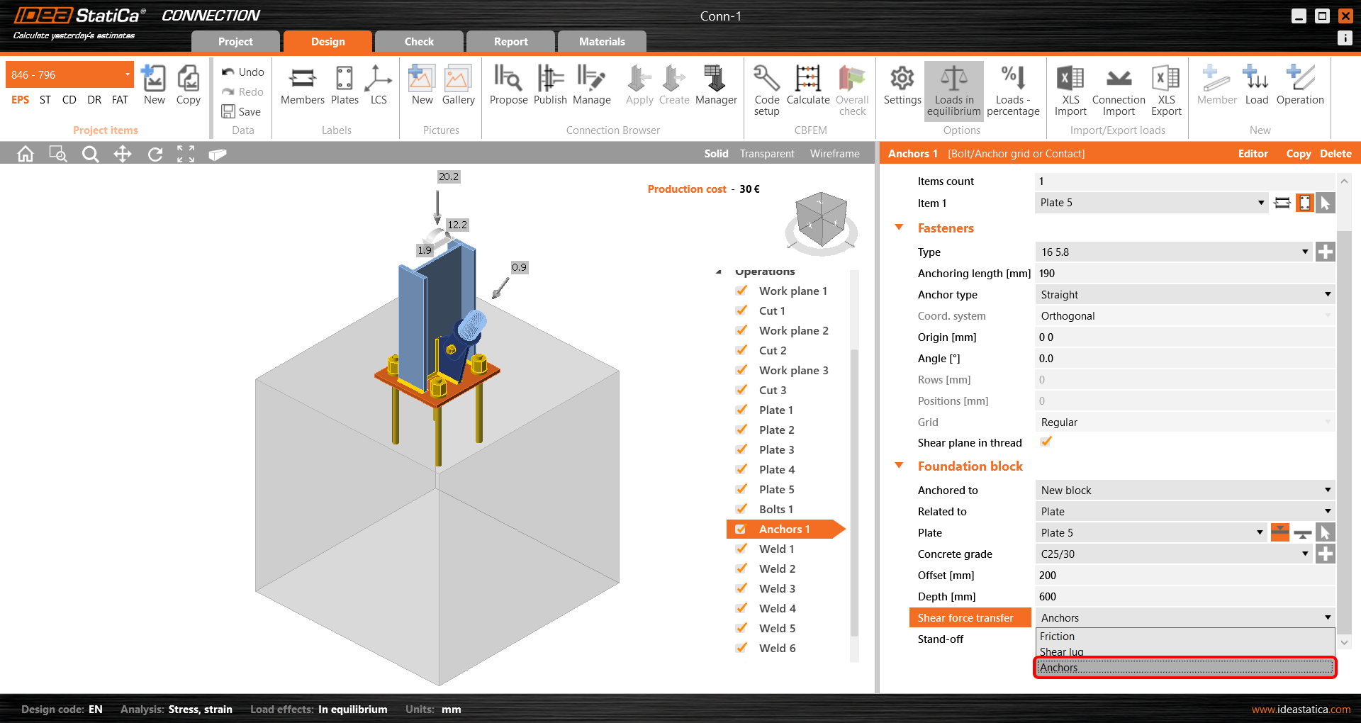
And select the Shear forces transfer to Anchors at last.
Code-check and Report
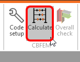
Now run a code-check using the Calculate icon in the CBFEM panel from the top ribbon.
Within IDEA StatiCa Connection you can carry out many different types of analysis and code-checks. For more information, please see here.
Once the code-check is finished in the Report tab you can create the report containing results and diagrams for your connection model.
The report can be printed or saved in several formats. For more information, please see here.
Save and Exit this connection back to Checkbot.
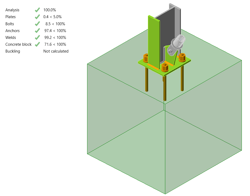
In Checkbot, you will see that there is a green tick next to the connection. This means that the connection is valid and has passed all code-checks. In the Connection panel, you can also see a representation of the connection and a summary of the code-check results.
If multiple connections are present in Checkbot then each must be opened, designed, and code-checked.
In the example below, you can see that our baseplate connection has passed the respective code check while the remaining connections are yet to be validated.
You can continue with the design of additional connections using the same approach presented above.
Synchronize model
Sometimes, there are changes to your FEA/BIM model such as different member section sizes or loads. These can be synchronized between Checkbot and the FEA/BIM model.
There are two possible alternatives:
- Synchronize the Current item (if one or more joints are selected)
- Synchronize the whole imported Structural model
To test this feature, you can change a member section size or shape in your BIM application, or amend a load case or combination etc: change the selected column to a smaller section.
In Checkbot select the designed connections (there may be more than one) and from the Current item panel select Sync.
The Checkbot project will be updated, connection design is preserved but the results will be invalidated. You can see that the column is now updated - matching the change in the BIM model.
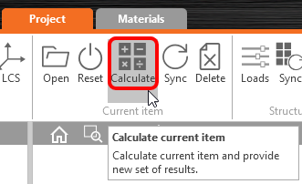
Simply code-check the highlighted connections again by selecting Calculate from the Current item panel. Please remember that bigger changes in the model might require additional validation steps with the affected connections (as above).
If the connections do not give the desired results, then you can open them again to optimize the design (i.e. strengthen if they fail the code-check or lighten if the utilization is too low).
You have successfully linked Advance Steel with IDEA StatiCa Connection via Checkbot.
Read more about the known limitations of the Advance Steel BIM link.


