Progettazione strutturale di una trave in acciaio (EN)
Nuovo progetto
Inizia avviando IDEA StatiCa e selezionando l'Member application (scarica l'ultima versione).
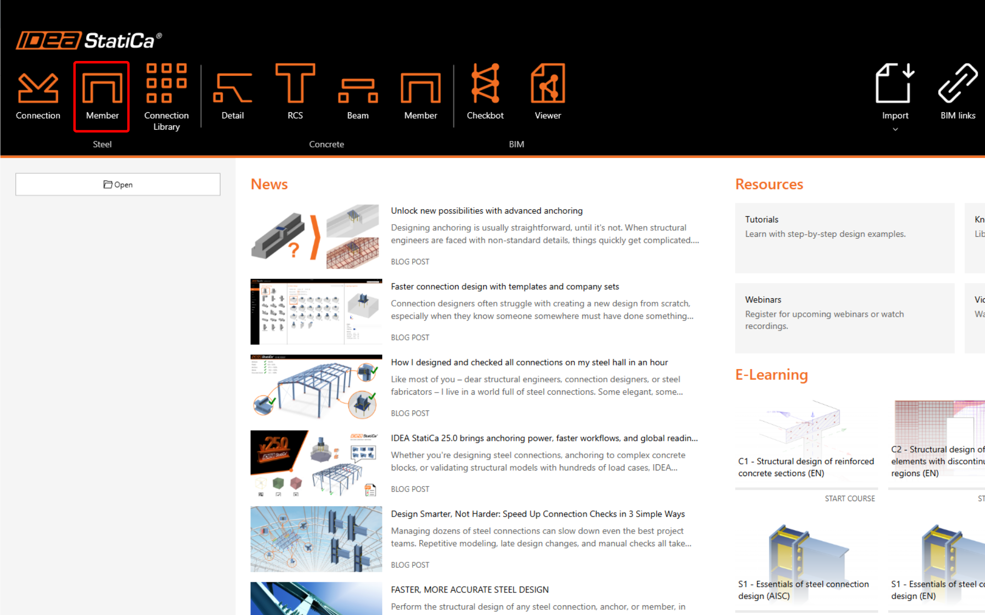
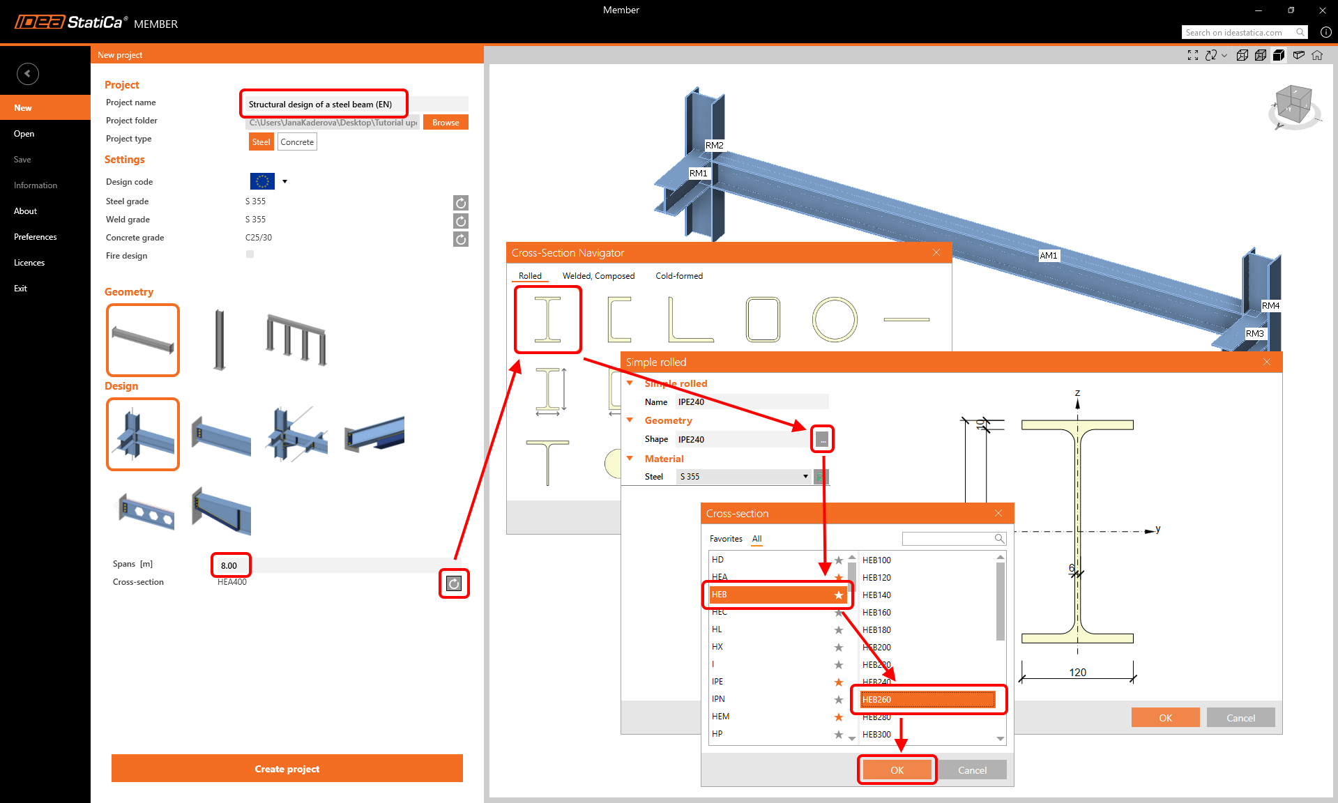
Crea un progetto Nuovo (barra laterale sinistra) e inserisci il nome. Utilizza la geometria della trave e il progetto con gli elementi correlati. Imposta la luce a 8,0 m, seleziona la sezione trasversale HEB 260 per la trave e clicca su Crea progetto.
Elemento analizzato
In questo esempio è presente un solo elemento analizzato - AM1, creato dal modello.
Elementi correlati
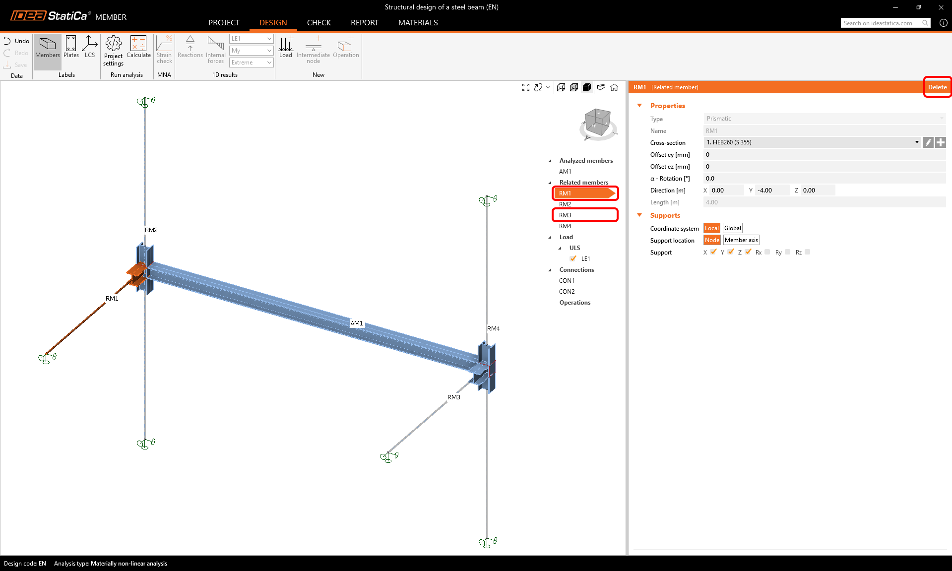
Quattro elementi correlati sono stati creati automaticamente. Tuttavia, è necessario mantenere solo le due colonne. Le altre due travi di collegamento possono essere eliminate per finalizzare la configurazione.
Seleziona ed elimina gli elementi RM1 e RM3.
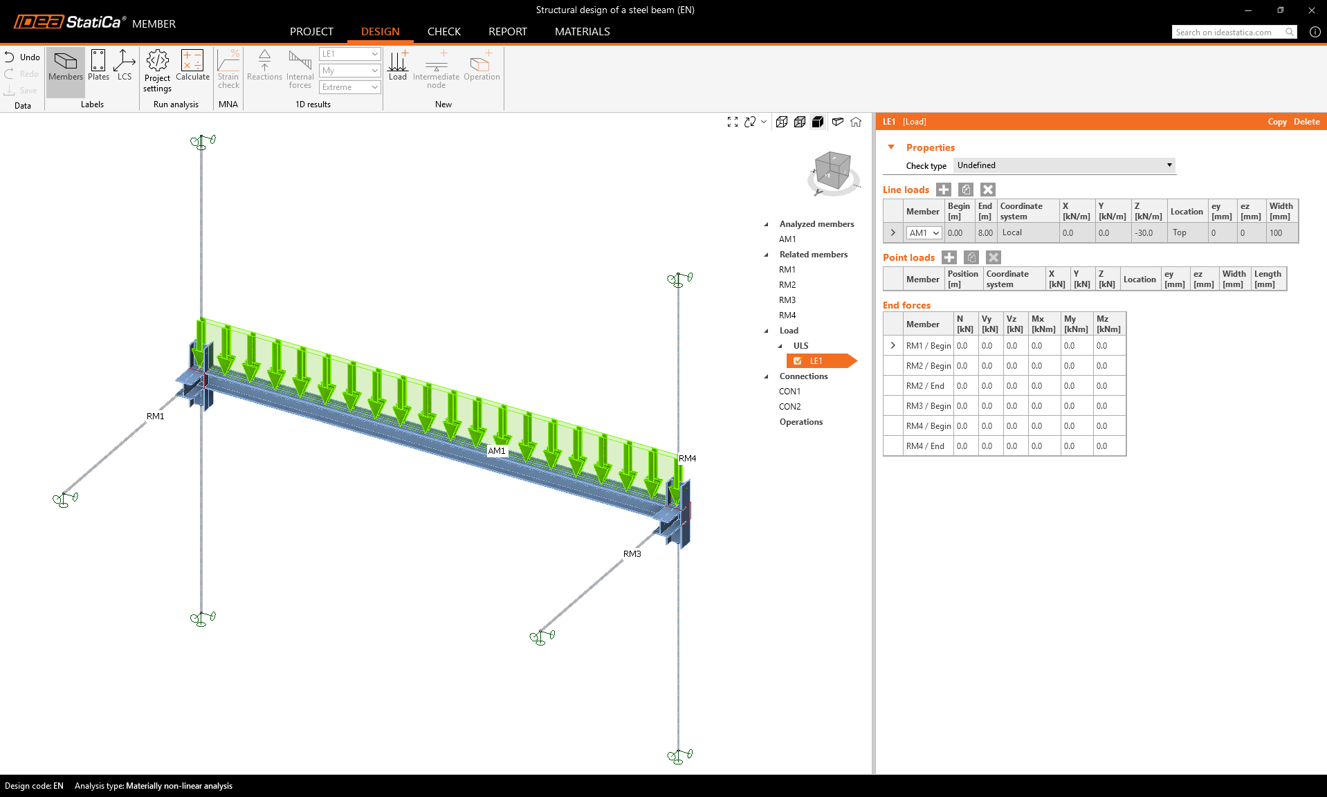
Carichi
Definisci il carico permanente sulla trave come Carico lineare e imposta i relativi parametri.
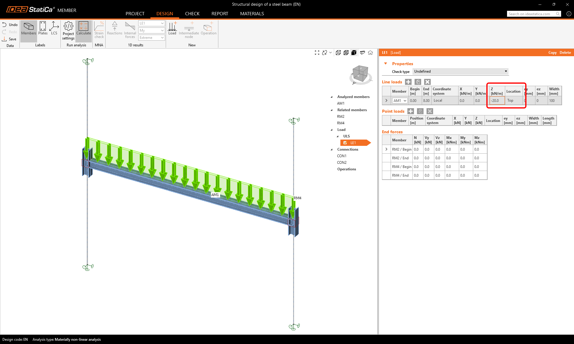
Modifica il valore del carico SLU/LE1 a -20 kN/m nella direzione z agente sulla flangia superiore.
Collegamenti
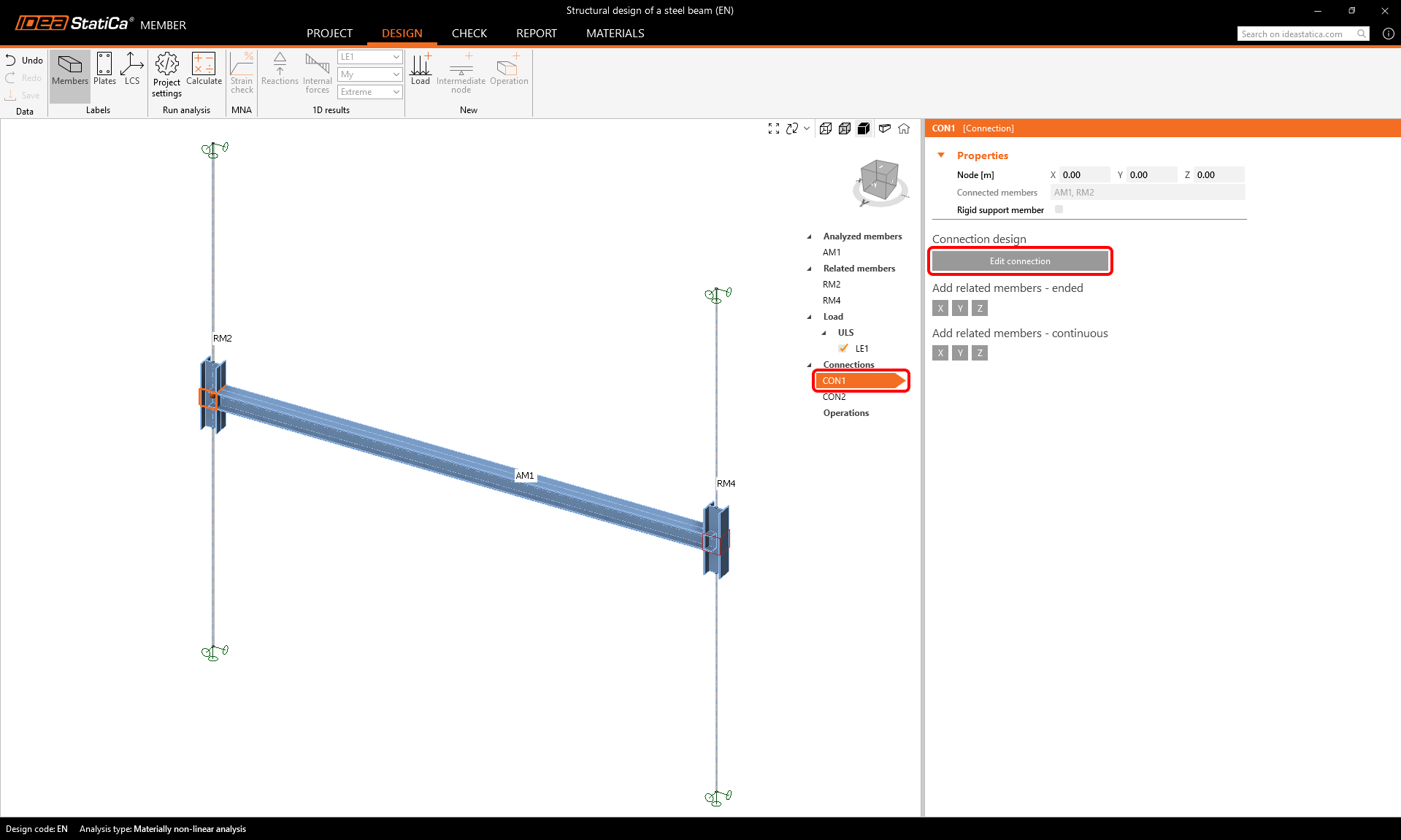
Per definire i collegamenti, seleziona l'elemento CON1 e poi Modifica collegamento.
Esistono diversi modi per modellare questo semplice collegamento:
- Utilizzando un'operazione con piastra d'estremità
- Utilizzando un esempio dalla Connection Library
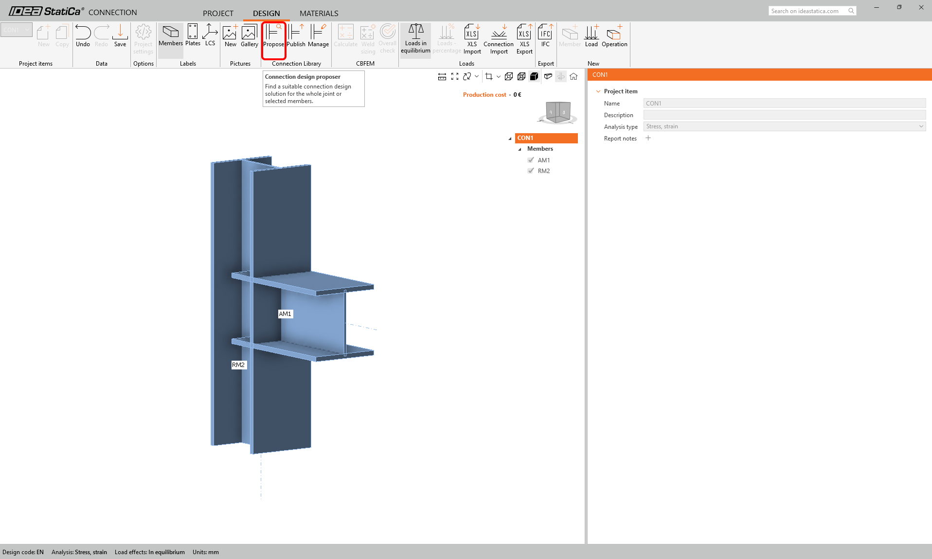
Cercheremo un modello adatto nella Connection Library - seleziona il pulsante Proponi.
Scorri la libreria e trova questo progetto:
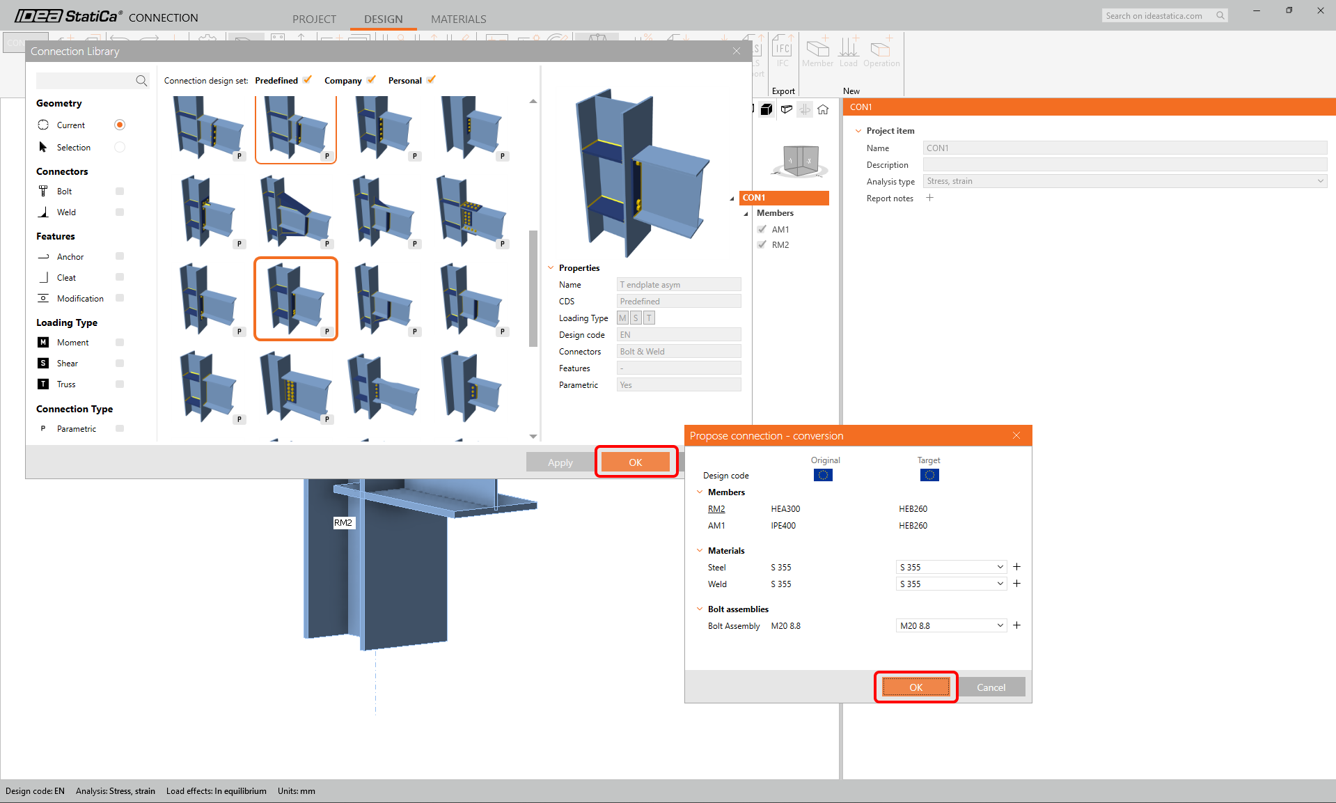
Modifica i parametri del modello parametrico: 2 file superiori, 2 file inferiori, distanza della colonna di bulloni 160 mm, prima fila, interasse dei bulloni e distanza dal bordo dei bulloni - tutti 50 mm. Tipo e dimensione del bullone M16 8.8. E deseleziona l'opzione irrigidimento.
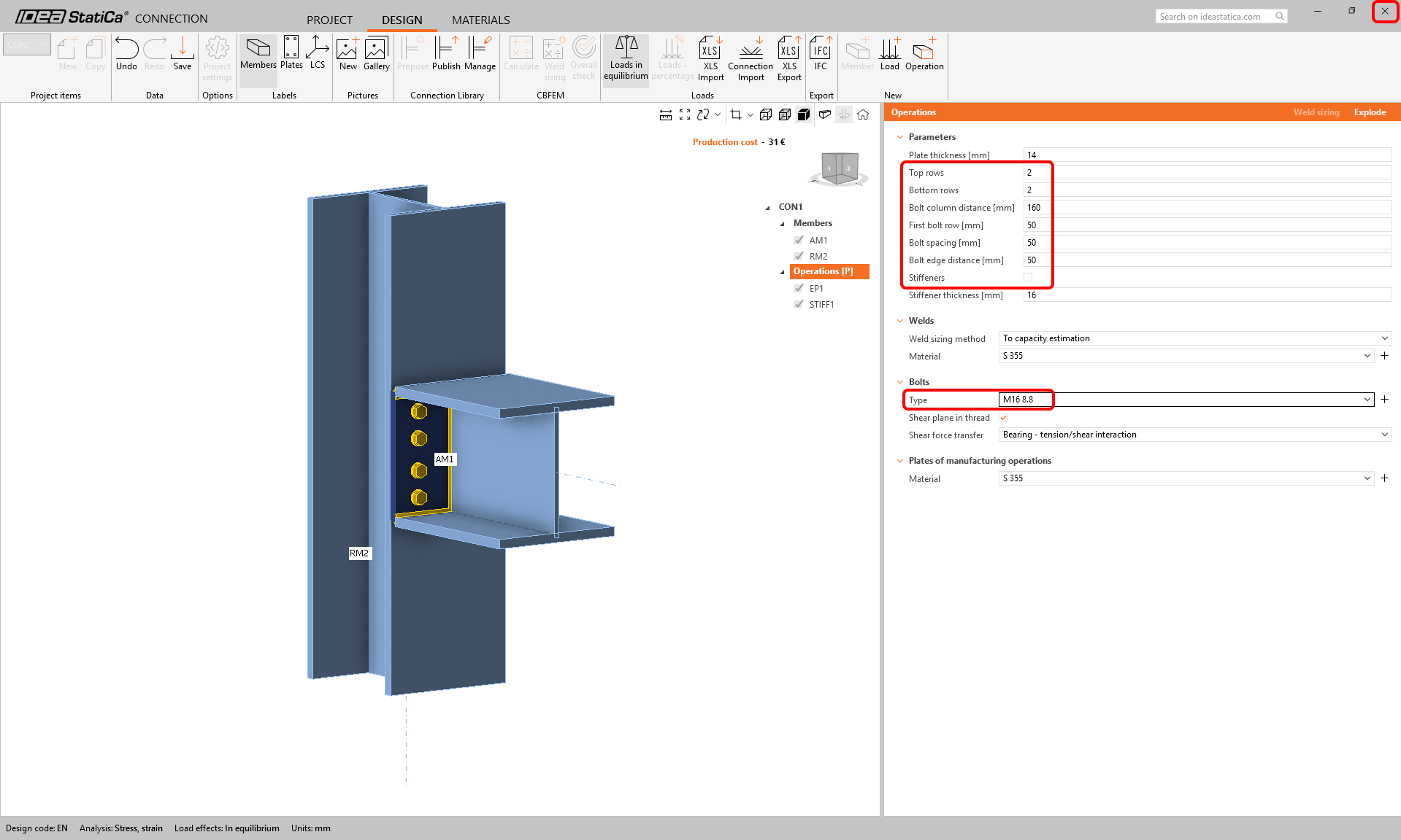
Salva e chiudi il progetto del collegamento e torna al progetto Member.
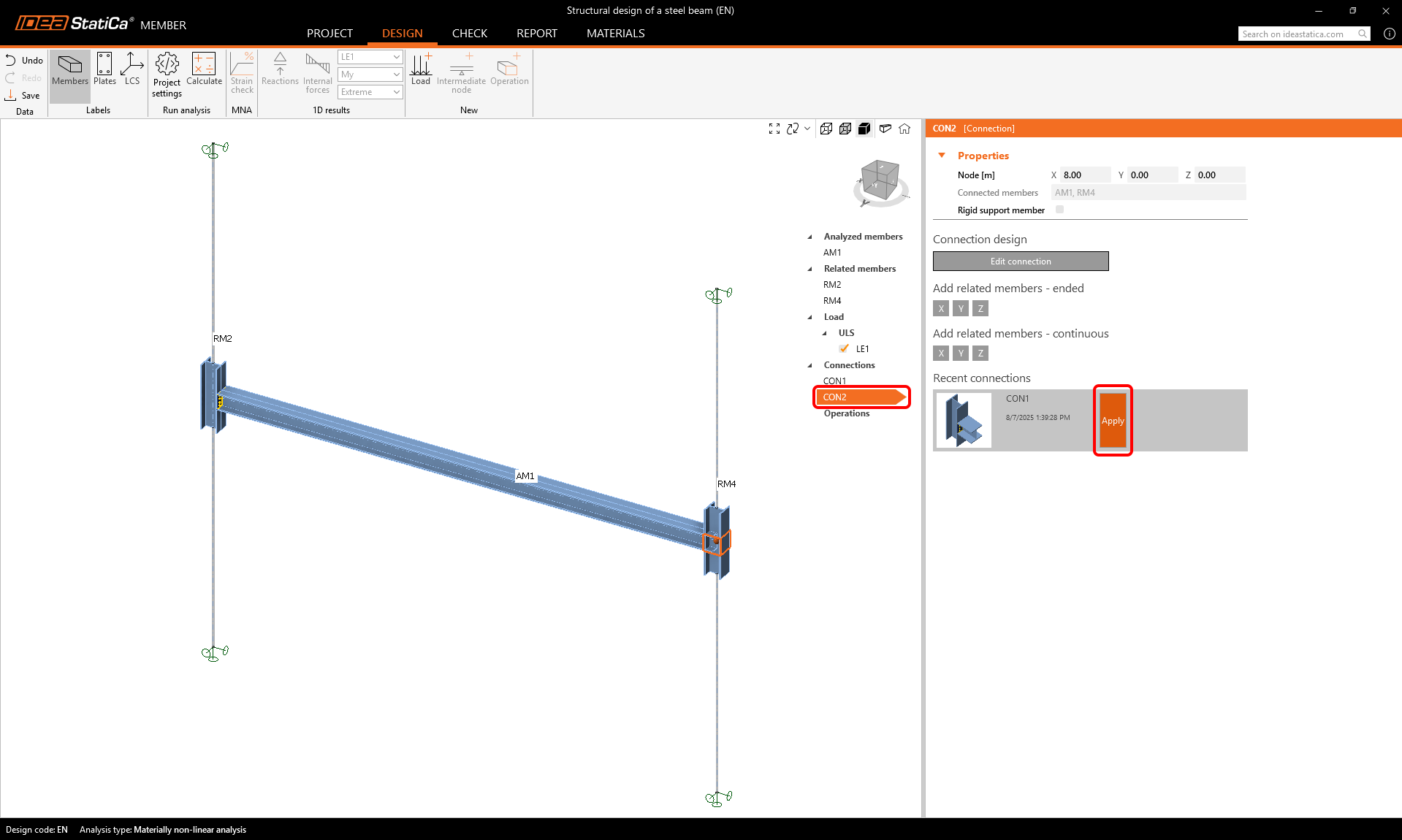
Per progettare il secondo collegamento, seleziona il collegamento CON2 e clicca su Applica per copiare il progetto proposto dal collegamento CON1.
Verifica
Esistono tre tipi di analisi che si susseguono.
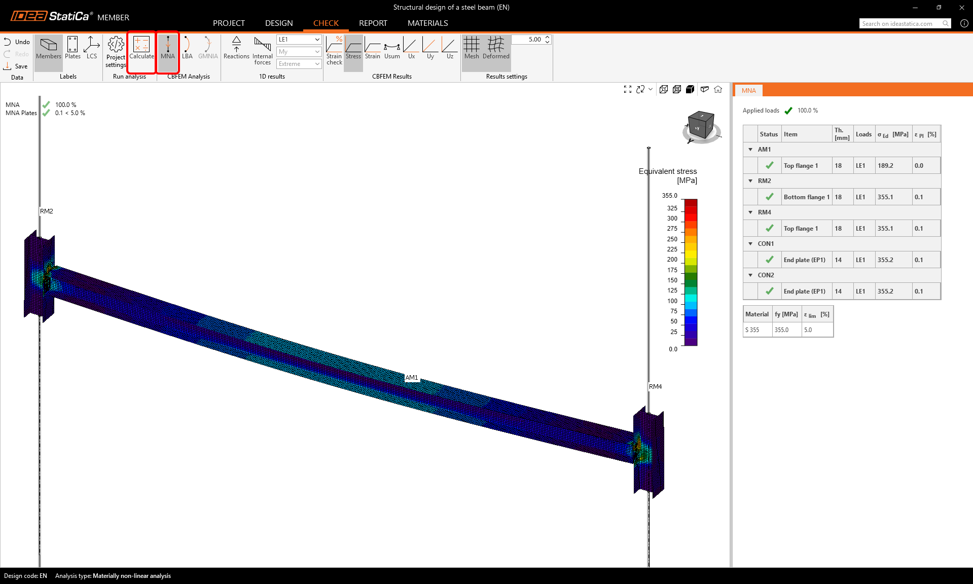
Per prima cosa, avvia l'Analisi Materialmente Non Lineare (MNA). Seleziona la scheda Verifica, MNA, e clicca su Calcola.
Puoi verificare visivamente la distribuzione delle tensioni sull'elemento cliccando sul pulsante Tensione nella barra multifunzione superiore e selezionando Rete, Deformata per visualizzare la forma deformata.
Il secondo passo consiste nell'eseguire l'Analisi Lineare di Instabilità (LBA) e cliccare su Calcola.
Esamina i diversi modi di instabilità nelle righe della tabella LBA nei risultati.
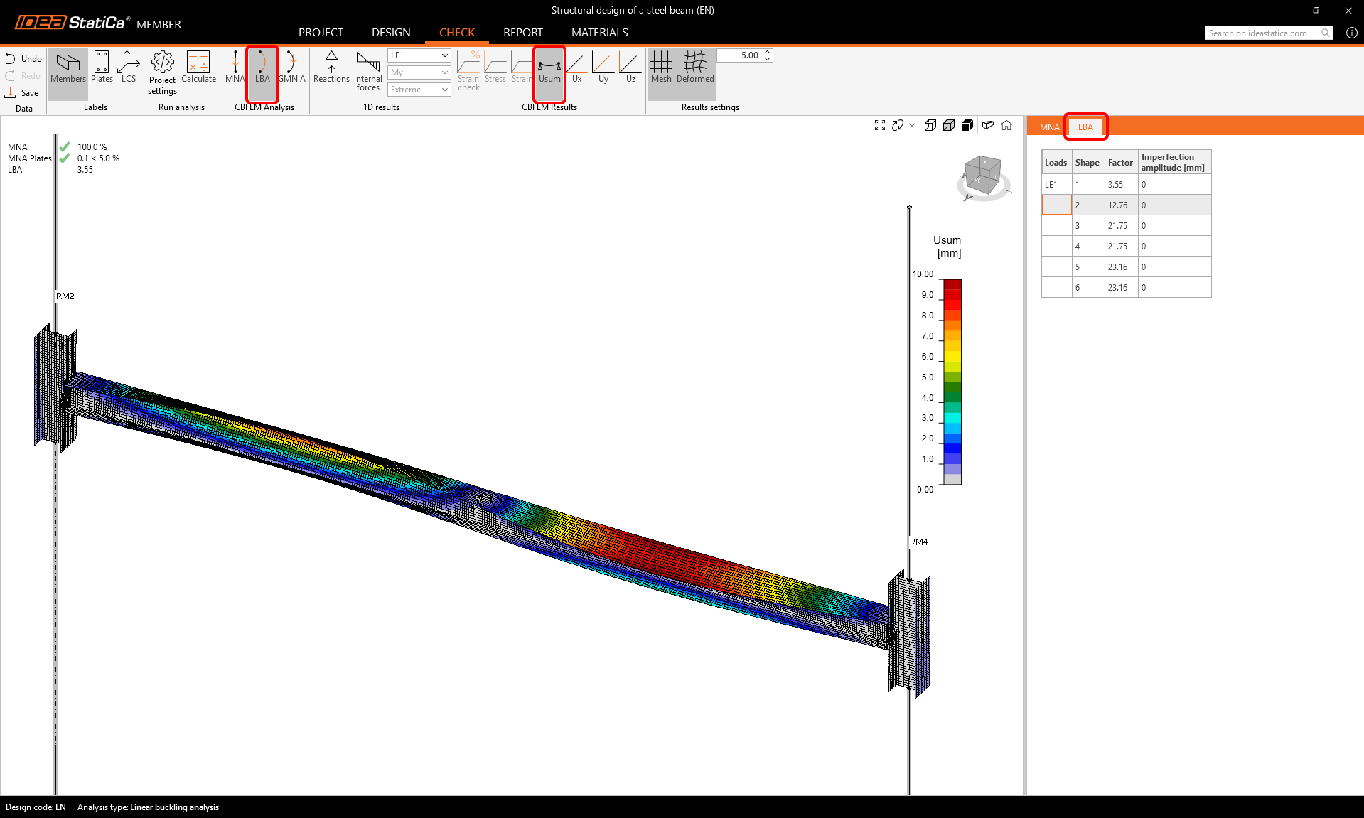
Come si può vedere, i primi due fattori di instabilità sono inferiori a 15, quindi in questo caso è necessario eseguire l'Analisi Geometricamente e Materialmente Non Lineare con Imperfezioni (GMNIA). Per ulteriori informazioni, consultare il Background teorico.
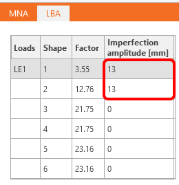
Per la GMNIA, è necessario impostare le imperfezioni (ampiezze delle imperfezioni geometriche iniziali).
Inseriamo i valori 0,5 x L/300 = 0,5 x 8000 mm/300 = 13 mm.
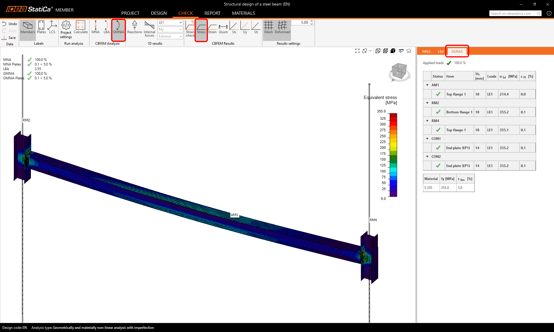
Avvia il calcolo dell'Analisi Geometricamente e Materialmente Non Lineare con Imperfezioni (GMNIA) selezionando GMNIA e cliccando su Calcola.
I risultati mostrano che le dimensioni dell'elemento sono sufficienti anche in presenza delle imperfezioni iniziali, e supera le verifiche normative, tenendo conto anche del rischio di perdita di stabilità.
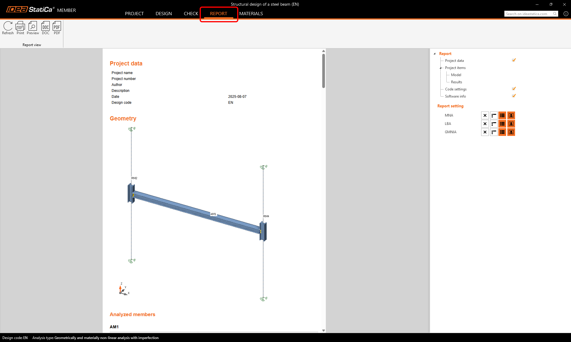
Relazione
Infine, vai alla scheda Relazione. IDEA StatiCa offre una relazione personalizzabile da stampare o salvare in formato modificabile.