
Is the base plate sufficiently rigid?
Why are fastenings so important?
Fastenings play a crucial role in the integrity and safety of structural and non-structural elements. That is why dedicated standards, such as EN1992-4, have been developed. They address the challenges of steel-to-concrete connections and provide a reliable design method that ensures a safe load transmission between steel and concrete elements. EN1992-4 covers various types of fasteners (cast-in headed fasteners, post-installed mechanical and bonded fasteners), as well as different action categories.
The design of fastenings for use in concrete
The design of fastenings in concrete, according to EN1992-4, for static/quasi-static loading involves multiple code checks:
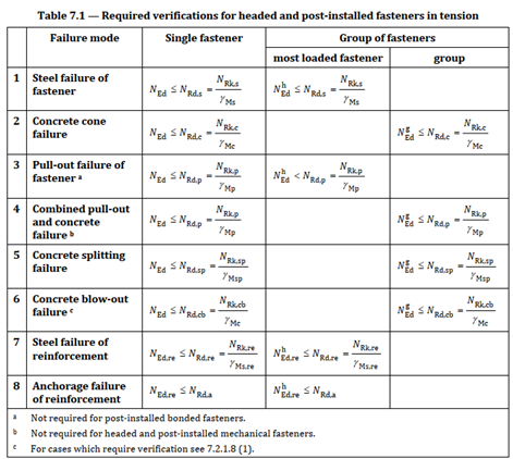
Fig. 1 Code checks for fasteners in tension
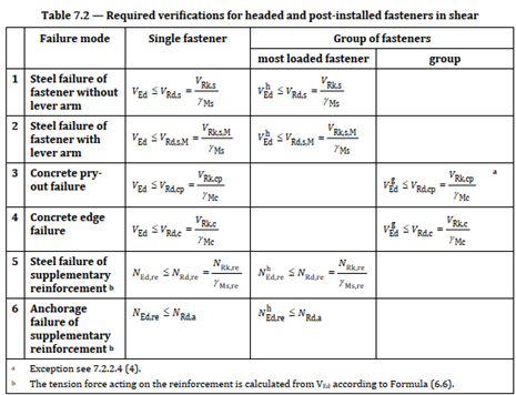
Fig. 2 Code checks for fasteners in shear
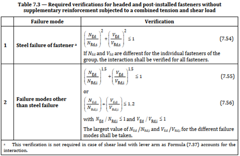
Fig. 3 Code checks to account for the interaction of tension and shear loads
The design process, as outlined in the Standard (Fig. 1 - Fig. 3), requires a detailed approach to ensure that all relevant code checks are satisfied. Each fastener type needs specific considerations. For example, mechanical anchors rely on mechanical interlock, while bonded anchors depend on the adhesive properties of the bonding material. The design process must account for these differences to ensure a reliable connection.
Let's take a closer look at one of these code checks. We will take the characteristic resistance of the fastener, or a group of fasteners in the case of a concrete cone failure (Fig. 4), as an example, which shows how sophisticated the design model is:
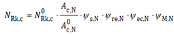
Fig. 4 The characteristic resistance of the fastener, or a group of fasteners in the case of concrete cone failure
There are four factors included in the equation to account for effects like shell spalling, disturbance of distribution of stresses, presence of supplementary reinforcement, and others. This reveals that not only the properties of the construction materials (steel, concrete), but also other factors, like the geometry of the concrete block, anchor grid, embedment depth, supplementary reinforcement, etc., have an influence on the final resistance, i.e., the governing failure mode for the given load combination. This demonstrates that the design of steel-to-concrete connections can be quite tedious and complex when done manually as it involves numerous calculations and iterations to optimize the design.
IDEA StatiCa Connection allows the user to design steel-to-concrete connections using post-installed mechanical fasteners or cast-in anchors with washer plates. Depending on the anchor type, there are many code checks to be calculated. Most of the code checks listed in Fig. 1 - Fig. 3 are calculated in IDEA StatiCa Connection based on the user's input and the parameters indicated in the standard. Some of them are not provided as they require product-specific factors, which are based on tests carried out using a standardized setup and evaluated according to applicable harmonized technical specifications. These factors can be found in technical approvals such as European Technical Assessment (ETA). Besides factors required for the calculation of design resistance, there are other important characteristics included in the approval, like minimum edge distance cmin, minimum anchor spacing smin, minimum height of concrete block hmin, safety factors, and more. The information about code checks that is not provided is described in the results tab as shown in Fig. 5.
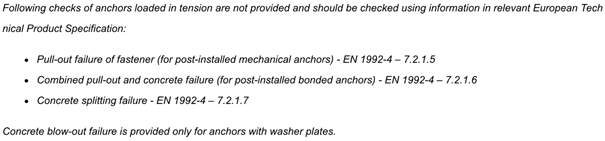
Fig. 5 A list of code checks that require product-specific characteristics
The stiffness of the steel base plate
Besides a list of required code checks, the standard specifies additional rules that must be adhered to. Among them are the rules for the derivation of forces acting on fasteners. When a bending moment and/or a tensile force is acting on a fixture, similar as in a steel-to-steel connection, prying forces may arise. These forces must be considered in the base plate design as this will lead to higher tensile forces in the anchors. This requirement is described in Clause 6.1 (4) and shown in Fig. 6.1 b of EN1992-4:

Fig. 6 Clause 6.1 (4) of EN1992-4
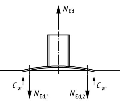
Fig. 7 Amplification of tension forces acting on a fastener due to prying forces Cpr
The code gives guidance on how to calculate the design tensile loads acting on a fastener, provided the fixture is sufficiently rigid, which means an assumption of linear strain distribution is valid (as in beam theory). However, if the requirements set out in Clause 6.2.1 are not met, the elastic deformation behavior of the steel base plate is taken into account. This effect is considered in IDEA StatiCa Connection, as the calculation using the CBFEM method allows capturing the flexural behavior of the base plate, including the stiffness of the attached profile, welds, and foundation pad (modeled using the Winkler subsoil model). In the next section, we will take a closer look at the influence of the plate thickness on the resulting tensile forces in the anchors, equivalent stresses in column, and compressive stresses in a concrete block.
Some examples in IDEA StatiCa
Let's check out some examples I have put together using IDEA StatiCa
Here, the anchor layout (two rows with three anchors), embedment depth, concrete block dimensions, as well as material properties, remain the same for both investigated cases. What will be adjusted is the base plate thickness (10, 20, and 30 mm), and the applied load effects – for case no. 1, that is a tensile force where N = 100 kN, and for case no. 2, that is a compression force where N = -100 kN. These assumptions will allow us to easily verify the influence of the parameters on the outcomes, i.e., the axial forces of the fasteners, equivalent stress in the column, and compression stress in concrete. The model is shown in Fig. 8 below.
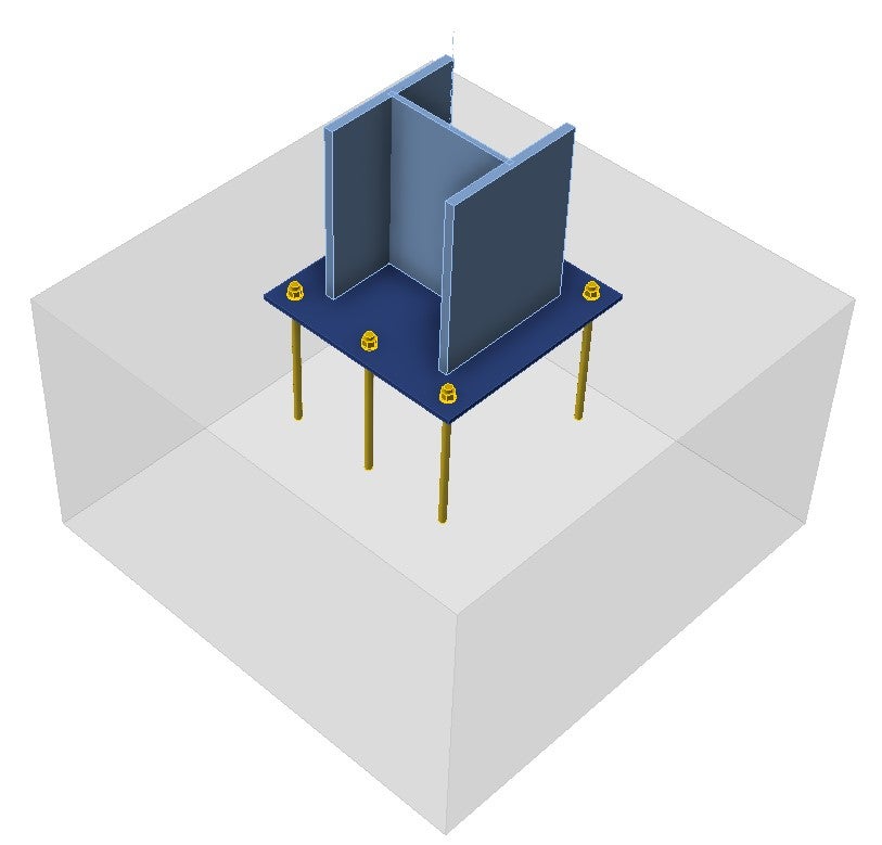
Fig. 8 Model in IDEA StatiCa Connection
Let's start with case no. 1, here are the results for the investigated examples:
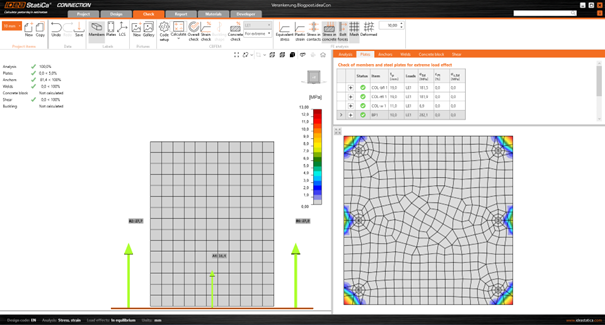
Fig. 9 Case no. 1, base plate thickness = 10 mm, equivalent stresses
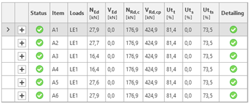
Fig. 10 Case no. 1, base plate thickness = 10 mm, tensile forces in anchors
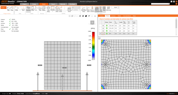
Fig. 11 Case no. 1, base plate thickness = 20 mm, equivalent stresses
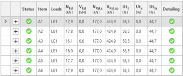
Fig. 12 Case no. 1, base plate thickness = 20 mm, tensile forces in anchors
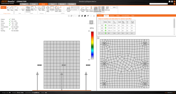
Fig. 13 Case no. 1, base plate thickness = 30 mm, equivalent stresses
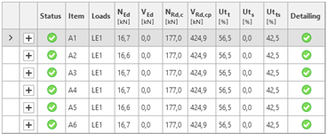
Fig. 14 Case no. 1, base plate thickness = 30 mm, tensile forces in anchors
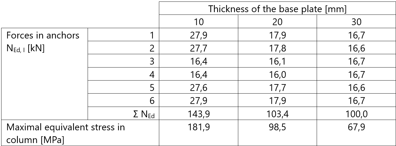
Tab. 1 A summary of the results for case no. 1 (N = 100 kN)
As expected, by increasing the plate thickness, the prying forces decrease, with tfix = 30 mm, no prying forces are present and the load is uniformly distributed among all anchors in the group. Comparing the forces for most stressed anchors in the group, there is a 67% difference between an elastic base plate (tfix = 10 mm, NEd,1 = 27.9 kN) and a rigid base plate (tfix = 30 mm, NEd,1 = 16.7 kN). Consideration of the flexural behavior of the steel base plate also affects the stress distribution in attached plates as well as in the welds connecting the elements. This shows how important the verification of base plate stiffness is in the design process.
The results for case no. 2 show the influence of plate thickness on the distribution of the compression stress in concrete:
Case no. 2, base plate thickness = 10 mm, equivalent stresses, stress in concrete
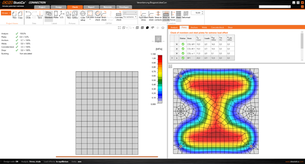
Fig. 16 Case no. 2, base plate thickness = 20 mm, equivalent stresses, stress in concrete
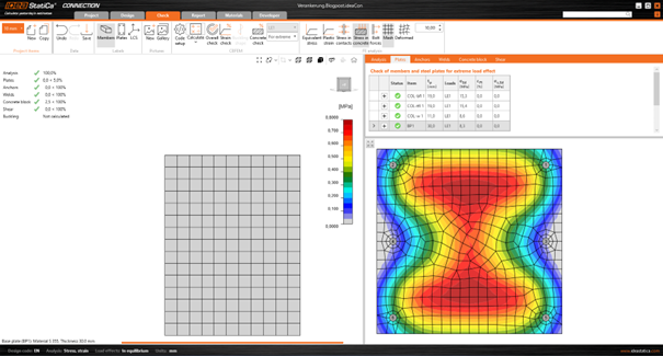
Fig. 17 Case no. 2, base plate thickness = 30 mm, equivalent stresses, stress in concrete
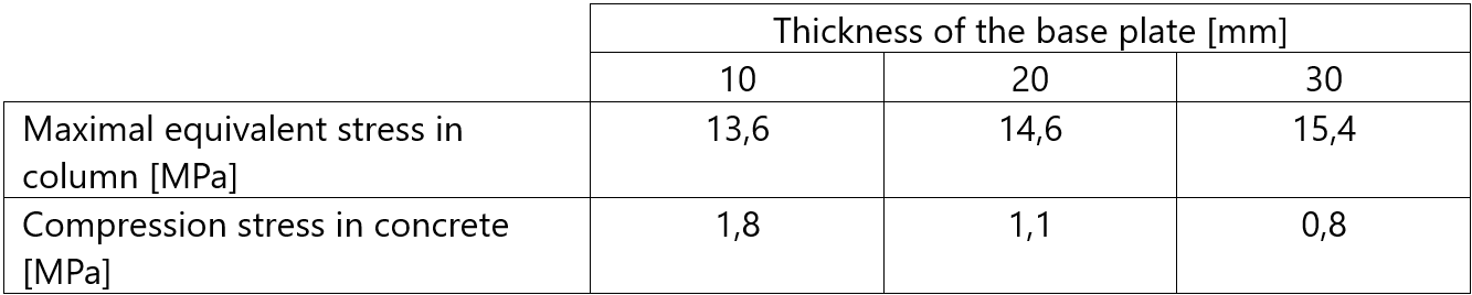
Tab. 2 Summary of the results for case no. 2 (N = -100 kN)
It can be noted that with increasing thickness, the stress is distributed more uniformly, which in turn lowers the maximum compression stress in concrete.
Summing up
With IDEA StatiCa Connection, the user can accurately model the flexural behavior of the steel base plate and verify its impact on the modeled connection. The software uses the CBFEM method to simulate the deformation of the base plate under the given load effects. This allows engineers to visualize the distribution of forces and identify potential issues related to the elastic behavior of the steel base plate, or to confirm the correctness of the assumption of a linear strain distribution stated in EN1992-4. It is a crucial part of the design process for steel-to-concrete connections, as even relatively thick base plates may not fulfill the requirements of a rigid base plate, and omitting this verification might lead to an underestimation of the tensile forces in the anchors, as shown in the examples above.
…one more thing
In the latest version of our software, Version 24.0, a beta version of a direct link between IDEA StatiCa Connection and Detail has been implemented. This allows the verification of reinforced concrete footings (ULS) using 3D Detail (based on the CSFM method). In our support center, you can find a step-by-step tutorial on how to exchange the data between both programs, as well as how to run the calculation in our Detail application.
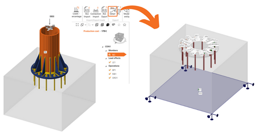
Fig. 18 BIM Link between IDEA StatiCa Connection and Detail (beta version)
Some more resources
You can read more about the topic here:
Import of anchoring from Connection to Detail (BETA)
IDEA StatiCa Detail – Structural design of concrete 3D discontinuities | IDEA StatiCa
If you want to read more about the latest version, check out the release notes for all the details.
Watch the Webinar Recording
This successful webinar, with over 1,500 registered attendees, provides a deeper dive into the topic. By reading this blog post, you can access the webinar recording and explore advanced techniques and practices.
Don't miss this opportunity and check it out!
Maak vandaag nog een proefrit met de nieuwste IDEA StatiCa
