Is the analytical approach enough to check member buckling?
In this blog, we will revise the analytical approach, with its buckling length determination, that was adopted to calculate and code-check the stability problems of steel members, such as column buckling and beam lateral torsional buckling. This procedure, dealing with the possible loss of stability, is well-established in design standards such as EN 1993-1-1 or AISC 360-22.
But can hand calculations survive the boom of FEM-based technologies and numerical solutions? Do they still prove to be reliable and safe?
Let's explore the topic of steel member buckling with a simple example. There's no better source to learn a lesson from than a piece of real design marvel or, indeed, a mistake.
The standard way of structural analysis
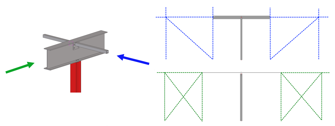
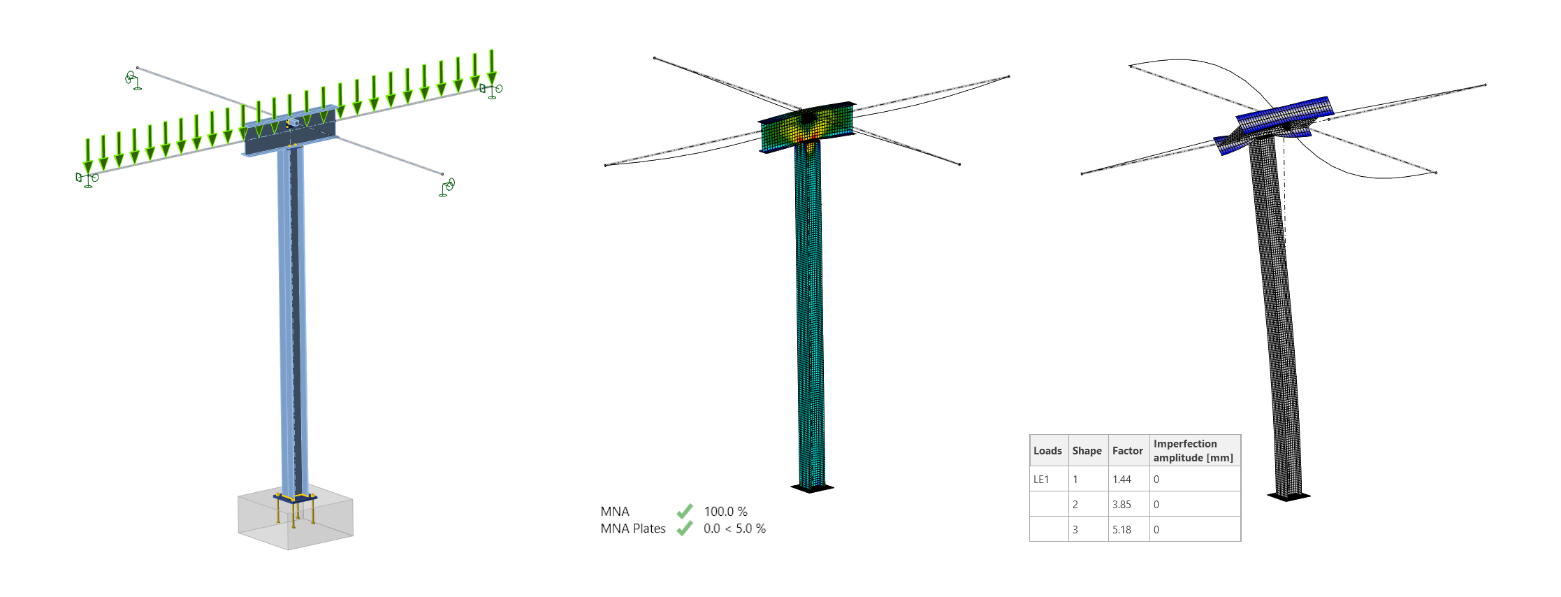
First of all, we will keep the project data anonymous. We will focus on a simple beam-column segment located inside a building to provide a wide-spanned space. On both sides, it is connected to the stiffened building body (see the image below of the connection detail with blue and green section views).
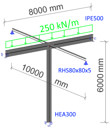
The column HEA 300 is 6 m long and fixed at the bottom by a thick base plate and four M30 anchor bolts. Beam IPE 500 is 8 m long, and it is seated at the column top and loaded at the member axis by a uniformly distributed load of 250 kN/m. The beam is supported on both sides by 5 m long RHS 80x80x5 bracings. All steel is grade S355.
Step 1: The global structural model
The first step is to create and analyze the global model. For this study, SCIA Engineer was employed, but any other FEA solution can replace it (SAP2000, ETABS, Robot, STAAD.Pro, etc.). The model is simple and built straightforwardly, the only question is the end supports.
As per the project description, we can say the column bottom with its solid anchoring and thick base plate has fixed support, the main beam has pinned support with fixed torsion, and the bracing members, giving lateral-torsional stability, have pure pinned supports.
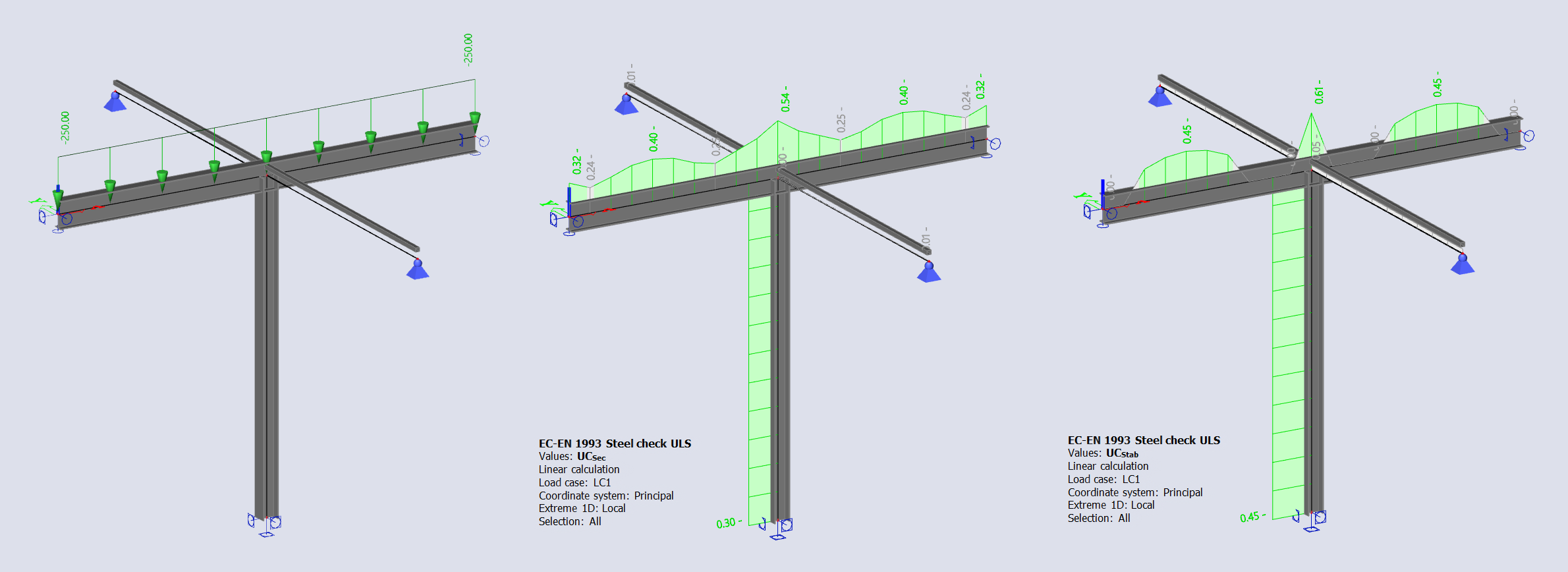
SCIA Engineer provides a complete ULS check as well as the stability check using the embedded analytical approach with the buckling lengths, critical force, critical moment, and overall buckling resistance of members based on the Euler's critical load.
In the calculation results, we can read that the section utilization peaks at 54% for the beam and 30% for the column. The stability check provides utilization of member buckling as 45% in the mid-span of the beam (lateral torsional buckling under bending moment My) and 45% in the column (bowing under compression N). The global model has passed the code checks.
Step 2: Buckling curve and buckling length
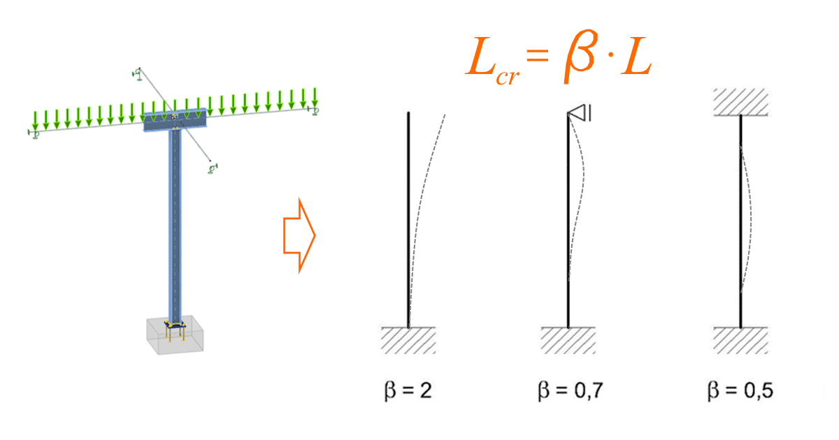
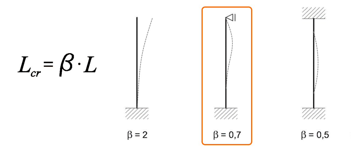
Let's verify the software results with a hand calculation. We will focus on the stability check here, and follow the analytical approach described in EN 1993-1-1 chapter 6.3, Buckling resistance of members. Because the global model is symmetrical in both directions, the analytical approach is simple. But first, we need to choose the buckling shape to calculate the buckling length as Lcr=beta*L.
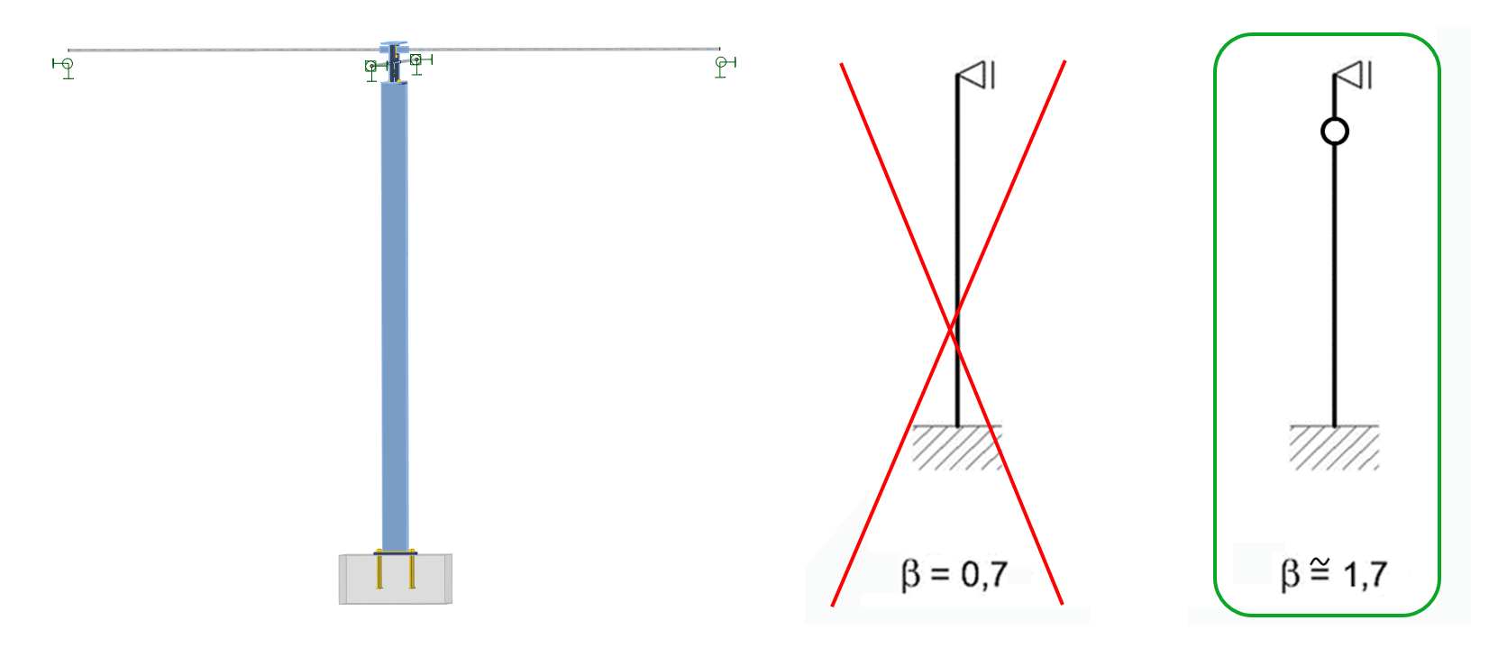
For the column problem of buckling under compression, we choose the fixed bottom and pinned top, since the anchoring is designed as stiff, the top of the column and the top are held by the beam in one direction, and the bracing members in the other direction. This results are in a beta factor of 0.7 in order to calculate the buckling length.
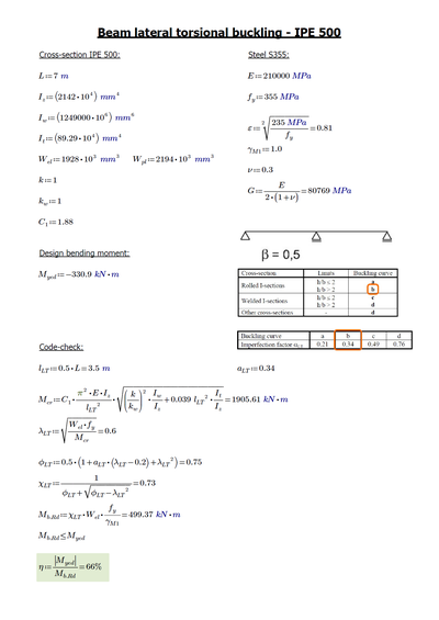
For the beam, we will inspect the lateral torsional buckling of the mid-span between the end support and the column connection. Thanks to the supports on both sides of the mid-span, we determine the beta factor as 0.5.
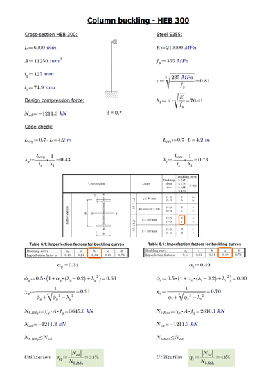
Now, we follow the equations as per the code - sum the section and steel properties and determine the appropriate factors and parameters such as slenderness ratio, and imperfection factors for buckling curves, critical force and critical moment to finally calculate the design buckling resistance of a compression member Nb,Rd and the design buckling resistance moment Mb,Rd.
The results of our hand calculation show a good match with those received from the SCIA Engineer analysis. Peak column utilization in stability is 43% and utilization of beam in lateral stability is 66%. Both structural members have passed the code checks.
Step 3: Code-checking the connection
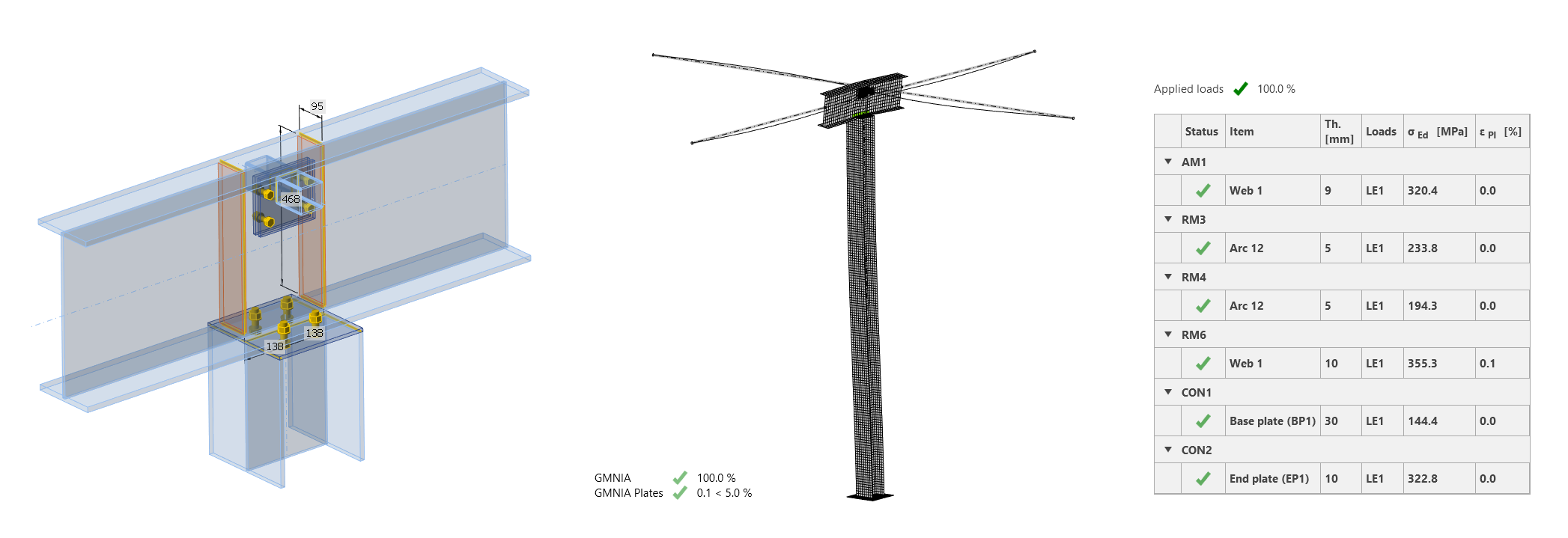
For checking the connections, IDEA StatiCa was used. This involved importing the geometry and load effects via the BIM link to Checkbot, opening the node in the Connection app, designing and calculating it, and delivering the report. As simple as typing these three lines of text, the job took a minute, and all connection parts passed the code checks.
So, what's wrong? Oh... it's the buckling
In the preceding lines, we basically repeated the real design process. So far so good? Surpriiise, the segment collapsed!!! Yes, soon after the project was finished, the beam-column system lost its stability.
For the theoretical investigation of the reason for failure, we can either use experienced engineering judgment or IDEA StatiCa Member - the most advanced analysis tool nowadays for members subjected to buckling.
IDEA StatiCa Member shows the truth
Using the BIM links, we can again import the investigated column and beam with the distributed load and bracing members from SCIA Engineer to Checkbot and open it in the Member app. Or, we can easily model the structural part from scratch. Anyway, after a quick assembly of the model, we can run the analysis in three steps.
For the GMNIA analysis (geometrically and materially nonlinear analysis with imperfections), we need to input the imperfection amplitude. From the single equation, we obtain 24 mm for the first buckling shape and 2 mm for the second buckling shape. Both buckling imperfections and buckling shapes will be considered together.
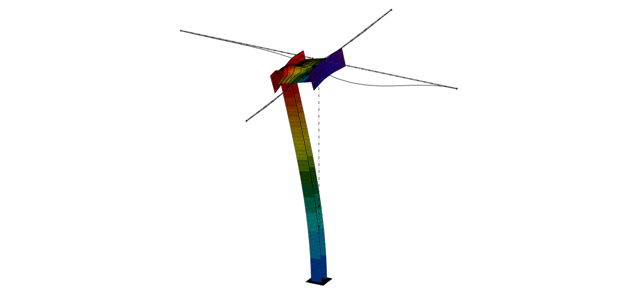
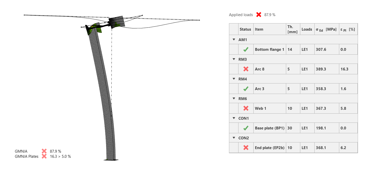
The GMNIA results show a clear failure of the model. The column buckles towards its top, causing the overturning of the beam. This was exactly the failure mode of the real structure.
But what's the difference from the analytical approach? There, we made an assumption of the simplified system (fixed-pinned column). But, since the beam web is not stiff enough, the column is prone to buckling, almost as if unsupported, at the top end!
So this is the big error we made during the analytical process - the column system actually works differently than "fixed-pinned" with a beta of 0.7, and we should define it rather as fixed-hinge-pinned with a beta factor of approximately 1.7. This would, of course, lead to failing code checks of the hand calculation.
How to prevent buckling? Make it stiff!
Now, as we have revealed and described the mistake, let's think of how it could have been averted. As mentioned, having good expertise and spotting the problem or using the Member app would have prevented the disaster.
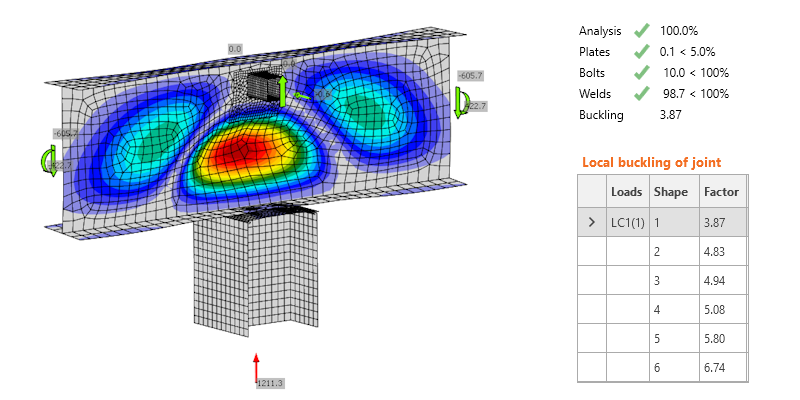
But since in the original job Connection app was involved, doing the buckling analysis would raise a red flag as well. Although the bracing members stabilize the beam at its sides, their upper position and overall stiffness is too low, and the beam web is simply too tall and soft.
The straightforward reaction (or prerequisite) is indeed to add stiffeners. Those were most probably unwanted due to the architectural or project requirements and neglected thanks to an inexperienced engineer, but perhaps adding them only to the back of the beam would have been acceptable. We can do that in the Member app in seconds, recalculate the project, and observe the dismissal of the plastic hinge. The system now works as assumed at the beginning of the story (beta of 0.7), and the structural part passes all code checks.
Note: The role of local stiffeners in steel structures is quite an important topic, and we can learn about their impact from various sources (even social media posts such as the Steel bridge in Albany collapse).
Conclusion
The answer to the title question is no clear YES or NO. But as we have witnessed, there are situations and projects where a critical mistake can be committed within the analytical approach. Luckily, there is a much more reliable, faster, visual, and comfortable way to do it with IDEA StatiCa Member. Time to say goodbye to buckling length estimations!
And to sum up today's lesson:
- The analytical approach is a simplification and may lead to a hazardous mistake.
- Small details can be critical for the stability of the whole structure.
- Never design such a detail without a stiffener (or IDEA StatiCa Member).
- For a 1st order analysis, in SCIA Engineer (or another FEA app), you should pay attention to your model boundary conditions; with the correct definition, the buckling length would be close to 1.7.
- For a more detailed buckling analysis in SCIA Engineer (or another FEA app), you can use advanced modules and features to evaluate buckling more precisely and safely.
You can download the package, including the SCIA Engineer project, IDEA StatiCa Connection and IDEA StatiCa Member projects, and MathCad script.
If you like, you can also watch the webinar recording on the same topic - Can the hand calculation check member buckling safely?


