Assessing bridge deviator strength: IDEA StatiCa vs. ABAQUS simulations
Box girder bridges use deviators to alter the external path of prestressing. This is an area of high-stress concentration and a potential weak point where poor design and analysis can lead to serious failures. In this paper, we will analyze a box girder bridge with external prestressing, specifically focusing on the deviator area. Our goal is to determine the ultimate capacity of the deviator through advanced numerical methods and simulate the state of stress, strain, and crack development. We will compare three different design options and assess their load capacity using the reliability approach outlined in relevant standards.
Model description
Geometry and material properties
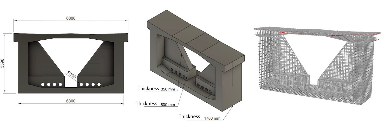
The cut-out of a bridge structure model made of concrete with the strength of C50/60 was used for simulation purposes. The model was transversely prestressed in the top slab with Y1860 S7-15.2 mono strands with an anchorage stress of 1,100 MPa. The reinforcement and its properties correspond to B500B properties.
Fig. 1 Geometry and reinforcement
Models
Three models with different levels of complexity were created for simulation purposes. The first model (hereafter referred to as model A) was solved as a 2D plane problem with a simplification in the form of plane stress. For the solution, the Compatible Stress Field Method (CSFM) [1] was used, which considers design assumptions for the calculation that are in accordance with current EN 1992-1-1 standards [3]. In the next stage, a simulation was carried out on a second model (hereafter referred to as model B), which is solved spatially using volume elements, taking into account also the third direction, i.e., the longitudinal direction of the box girder bridge. For model B, it is assumed that the initial stress in the longitudinal section direction of the structure is zero and, therefore, satisfies the assumptions made in model A, where a plane stress model is used. The solution of the 3D model is based on the Drucker-Prager constitutive model "Concrete Damage Plasticity" [2]. All inputs are in accordance with the reliability approach based on the reliability coefficients given in the standards [3]. The third model (henceforth referred to as model C) differs from model B by the initial condition of longitudinal compressive stress in the box girder section. Therefore, the initial condition differs from model A.
CSFM – model A
Assumptions
The model used in this study comprises of both 2D concrete and 1D reinforcement finite elements. It is assumed that the concrete is responsible for transmitting only the compressive stresses, whereas, the reinforcement carries the tensions. The tensile strength of the concrete is not taken into account, however, it is considered in the model in the form of tension stiffening on the reinforcement material diagram. The model also takes into account the compression softening of concrete due to transverse tensions, based on fib MC 2010. The cohesion of concrete, reinforcement, and prestressing reinforcement is included in the form of cohesion elements represented by a rigidly-plastic diagram with a long-plastic branch. For more information, please refer to the document "Theoretical Background for IDEA StatiCa Detail." [1].
Loads and boundary condition
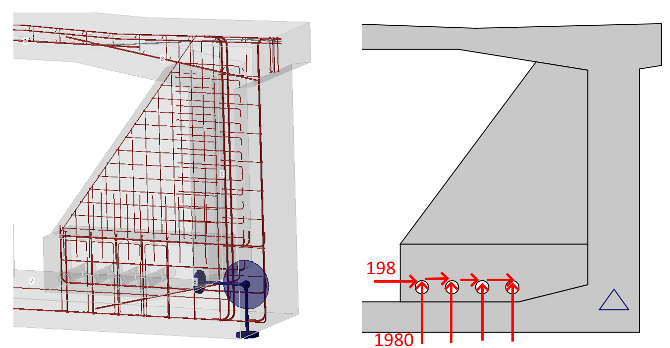
The deviator is situated at one-third of the span of the bridge structure. To simulate its response, supports were placed at the lower part of the wall of the box girder section and connected to the concrete reinforcement using distribution coupling equations at a radius of 300 mm. The boundary condition considers a fixed-pin support on one side (for horizontal and vertical movement) and a sliding-pin support on the other side (for vertical movement). The boundary conditions did not affect the stress states but predicted the location of the deviator violation during the simulation of the deviator response.
There are 31 wires in the external tendons, and the anchorage stress in the structure is 1394 MPa. This stress corresponds to the design radial forces in the deviator of 674 kN in the vertical direction and 67 kN in the horizontal direction (approximately 10% of the vertical force, taking into account the spatial tracing of the tendon). Using model A, it was determined that the magnitude of the vertical radial force from a single tendon at the deviator load-bearing capacity was 1980 kN. For this ultimate load, a nonlinear analysis was performed using individual models. The model takes into account a uniform distribution of the radial load in the longitudinal direction.
Fig. 2 Boundary condition and ultimate load
Results – model A
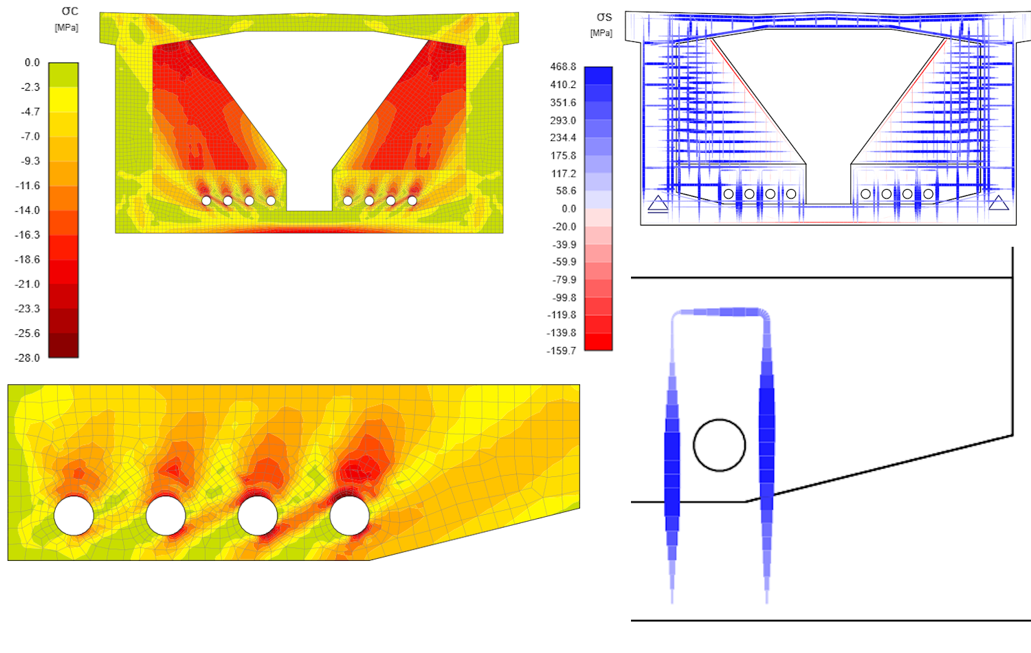
Based on simulation results, the highest compressive stress occurs at the point where the tendon comes in contact with the concrete deviator. This point is typically where the concrete has fully reached plasticity, generating a stress of -28 MPa. This stress value is the design strength of the concrete, taking into consideration the Éta factor to account for the brittle fracture of the material. The maximum reinforcement stress of 469 MPa is located in the area where the deviator and slab of the box girder section are tied up. This location is crucial from the point of view of strength and anchorage length, which is fully utilized. Additionally, the secondary location of high tensile stress is the wall of the box girder section. From a concrete perspective, the stiffening wall that connects the top slab of the box girder section is also a location of high concentration of stress.
Fig. 3 Principal stress in compression (left), stress in reinforcement (right), maximal stress in reinforcement and concrete in detail
The concrete damage model – models B and C
Method assumptions
Concrete Damage Plasticity (hereafter CDP) is based on the Drucker-Prager plasticity condition [2]. This model is suitable for materials with internal friction such as soils or concrete. The tensile strength is less than the compressive strength and the hydrostatic part of the stress tensor plays a role in the evolution of the plasticity surface. Under general stress, the plasticity condition has the surface of a rotating cone. The material model for compressive and tensile stresses also considers post-critical behavior, which is controlled by the so-called damage parameters, taking values from zero to one (for near-zero elastic stiffness of concrete in compression or tension in the post-critical condition). The larger the damage parameter number, the more the element is violated and does not contribute to the stiffness contribution [2].
Material models
The uniaxial material model in compression and tension for concrete is based on Thorenfeldt's theory [4]. All inputs are design values that follow the reliability approach of EN 1992-1-1 [3]. The material model of reinforcement B500B is taken into consideration with tension stiffening in the plastic area, similar to prestressed rebars Y1860 S7-15.2.
FEA elements and concrete and reinforcement constraints
The C3D8, or hexa-element with a linear basis function and eight integration points, was used for the FEM model of concrete. The concrete and prestressing reinforcement comprises T3D2 elements that transmit only axial effects. The interaction between the reinforcement and the concrete is provided by MPC constraints on which tension-stiffening is taken into account, which covers, to some extent, the cohesion model or dowel effect. The supports are connected to the reinforcement by distribution coupling [2].
Fig. 4 Material model in compression (left), Drucker-Prager plasticity surface (middle), material model in tension (right)
Loads and boundary conditions
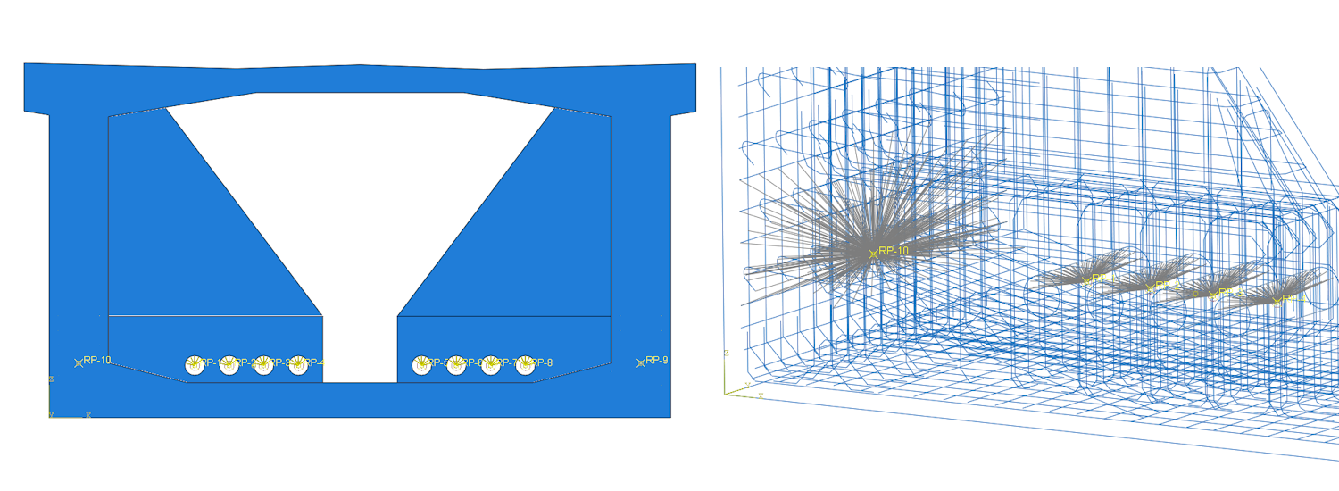
The boundary conditions for models B and C are identical. The model is force-loaded, and the point force is distributed over the contact area of the duct in the deviator by means of distribution coupling, which ensures a uniform load distribution through the thickness of the deviator. The point supports were bonded at a radius of 300 mm and through a 1,700 mm thickness of the box girder section with reinforcements using the equations of distribution coupling.
Fig. 5 Model (left), boundary conditions, and coupling equations (right)
Results – model B
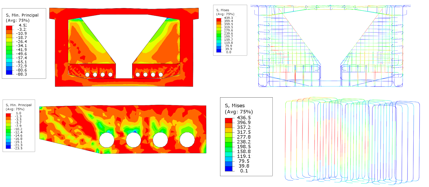
Model B assumes that there is zero initial stress in the longitudinal direction of the bridge, which is a conservative assumption. However, due to spatial stress and mainly due to concentration during the pushing of the corner, the area of connection of the stiffening wall to the upper slab of the box girder section experiences the highest compressive stress of -88 MPa. If we focus on the deviator region, we can observe a maximum compressive stress of -23.5 MPa in the area of contact between the tendon and the duct. The reinforcements near the tendon duct experience an extreme stress of 439 MPa, which ties up the bottom slab of the box girder section with the deviator. The place of extreme stress matches with model A.
Fig. 6 Principal stress in concrete (left), Von-Misses stress in bars (right)
Results – model C
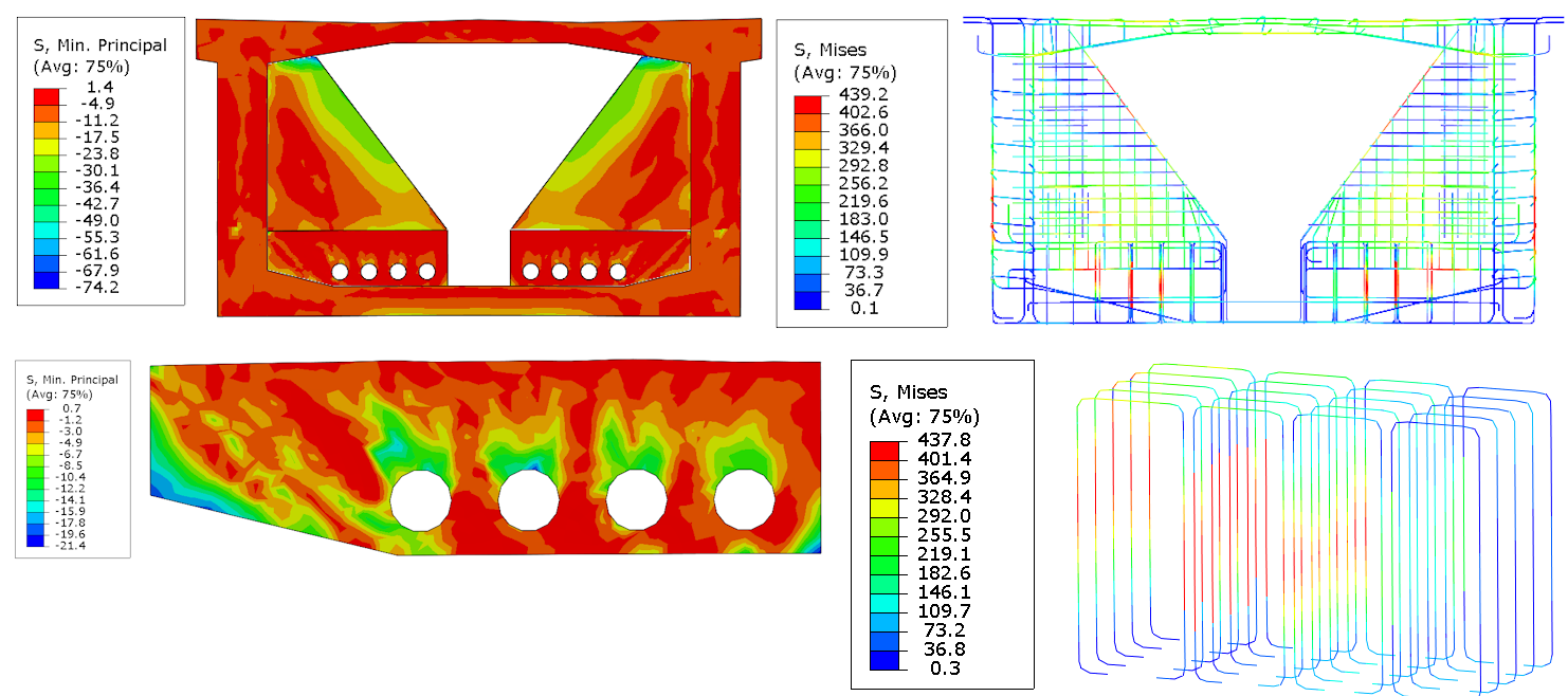
Model C assumes that the box girder section is under uniform compressive stress initially. As a result, the stress distribution changes, leading to a decrease in the critical compressive stress to -74 MPa, but the position remains the same. When focusing on the deviator area, the initial state of the section does not have a significant impact on the bearing capacity of the deviator since the decision-making part is inside the box girder section. The location and position of the reinforcement bars with maximum stress have not changed despite the different initial stress state in comparison to model B. The maximum stress has now reached 437 MPa.
Fig. 7 Principal stress in concrete (left), Von-Misses stress in bars (right)
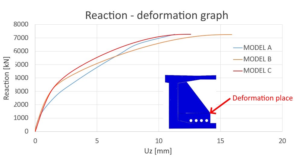
Reaction – deformation graph
Proof of the model's complex behavior is demonstrated through the reaction-deformation curve. The displacement extraction point has been predetermined within the deviator and stiffening wall area. The correct interpretation of results requires an unbiased approach. Consideration of the tensile strength in the concrete itself has caused discrepancies between models B and C and simplified model A. The simplified model A neglects the tensile strength of concrete. The tension-stiffening effect is only applied on the reinforcement bars material diagram. The design strength in tension of models B and C has been considered as 1.6 MPa based on Thorenfeldt [4], which is approximately 0.3 MPa lower compared to the design strength in tension according to EN 1992-1-1[3]. The resultant reaction has passed the ultimate limit state criteria.
Conclusion
Comparison
The goal of the verification was to check the stress and deformation state, with a focus on the bearing capacity of the deviator based on code assumptions [3]. The focus was to identify the most effective solution based on engineering practice and time savings. Model A considers the assumptions of plane stress and originates from a CSFM [1]. The "Concrete Damage Plasticity" Drucker-Prager [2] has been used for models B and C. The critical area of maximum principal stress in compression has been located in different locations between models A and B and C. Model A shows a compression stress of -28 MPa near the contact between the tendon and the deviator duct. For models B and C, the critical location is where the stiffening wall aligns with the top slab of the box girder section. The stress values at sharp corners have increased by up to -88 MPa for model A and -74 MPa for model B. The initial state of model C caused a decrease in principal compression stress of about 14 MPa. When we look at the deviator area, models B and C are similar to model A in terms of critical spot detection. Model B showed -23.5 MPa and model C showed -21.4 MPa. We can say that the stress state on the deviator is quasi-independent of the initial state, i.e., compression in the box girder section. The deviator plays a crucial role in reducing the magnitude of the principal compressive stress by increasing the tensile strength of concrete and stress distribution in the longitudinal direction. Simplified models like model A or the CSFM method can be used to solve this task efficiently. For all models, the duct of the deviator in the stirrups connecting the bottom slab of the box-girder section and the deviator is the critical location from the perspective of reinforcement. The maximum stress value in model A is 469 MPa, while models B and C exhibit stresses of 439 MPa, indicating the impact of the tensile strength of concrete. It can be inferred that there is a demonstrable consensus in the stresses in the concrete reinforcement from the critical location's perspective.
Solution effectivity
The best model for practical and time-efficient management of bridge deviators is model A. This is because the structural engineer can complete all tasks, from model preparation to post-processing, within a matter of hours, as opposed to models B and C, which take days to complete.
Literature
[2] Abaqus analysis user's manual. Abaqus analysis user's manual [online] www: https://classes.engineering.wustl.edu/2009/spring/mase5513/abaqus/docs/v6.6/books/usb/default.htm?startat=pt05ch18s05abm36.html
[3] ČSN EN 1992-1-1 ed.2 (731201). Eurokód 2: Navrhování betonových konstrukcí – Část 1-1: Obecná pravidla a pravidla pro pozemní stavby. Praha: Český normalizační institut, 2019, 208 s.
[4] Massone, L. M.; et al. Shear-Flexure Interaction for Structural Walls, 2006. ResearchGate. https://www.researchgate.net/publication/284079633_Shear-flexure_interaction_for_structural_walls (accessed Jan 01, 2006).
[5] ČSN EN 1992-2 (736208). Eurokód 2: Navrhování betonových konstrukcí – Část 2: Betonové mosty – Navrhování a konstrukční zásady. Praha: Český normalizační institut, 2019, 90 s.


