
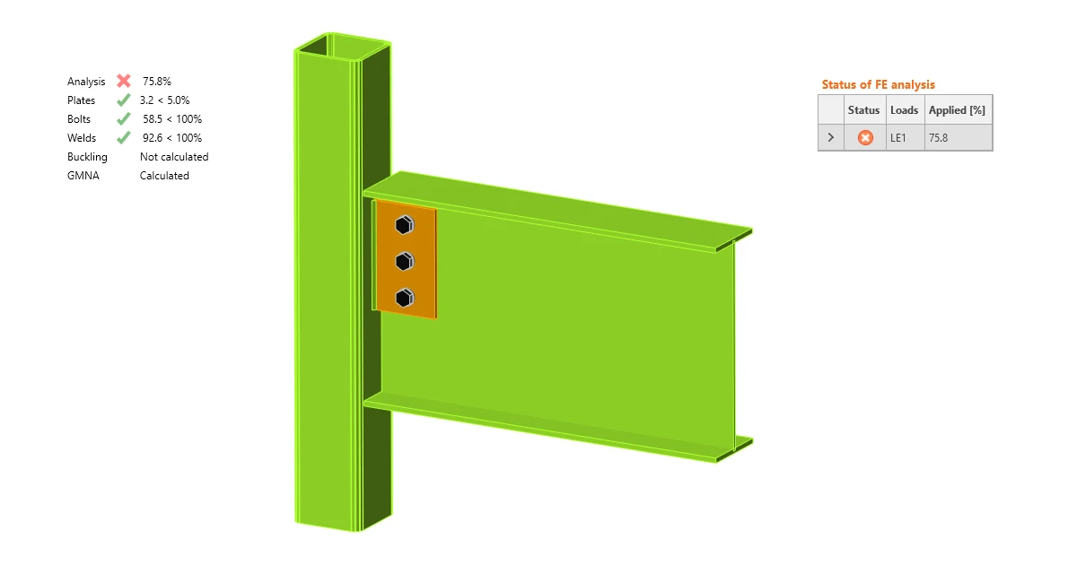


Analysis may also stop because of a singularity - read more about singularities in What is the singularity warning.
Stopping at limit strain
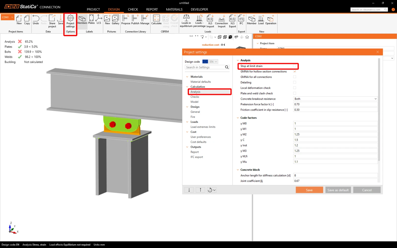
In the Project settings, there is an option to activate the Stop at limit strain feature. If this is turned on, the analysis halts when the capacity of any part of the connection (e.g., a plate, a weld, etc.) is reached. In case the connection is overloaded, the analysis stops before the inputted load effects are fully applied and the actual percentage of used loads is displayed.
To see the whole picture, go to the Code setup and uncheck the Stop at limit strain - the software will now run 100% of the loads.
Too complex joint
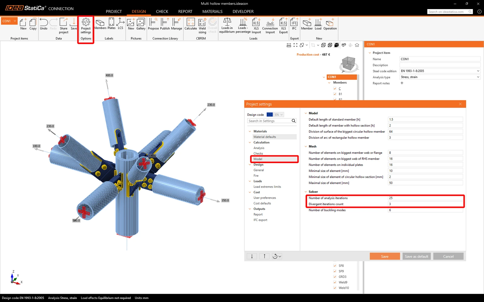
When the joint model is very complex, the default capacity of the finite element analysis might not be sufficient, resulting in the analysis 0%. In such a case, the calculation capacity can be adjusted to enable the analysis to be completed.
In the Project settings, raise the values of the Number of analysis iterations from default value 25 to higher (e.g., 50) and the Divergent iterations count from default value 3 to higher (e.g., 5). This adds to the calculation capacity but also results in the calculation taking longer.
Unstable analysis model of friction-based clamps
The CBFEM model in IDEA StatiCa can not directly calculate and code-check friction between plates when modeling a connection based on friction and preloaded bolts, such as a clamp connection.
In such a connection, where only tension/compression force is applied and transferred via contact (compression-only), there is a small prying shear force generated. Since friction is not taken into account and, thus, the shear force is not transferred, the model is unstable.
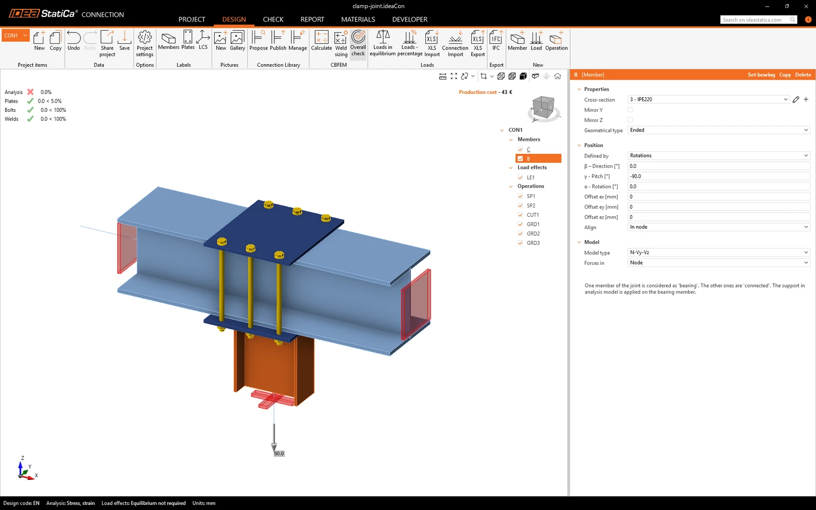
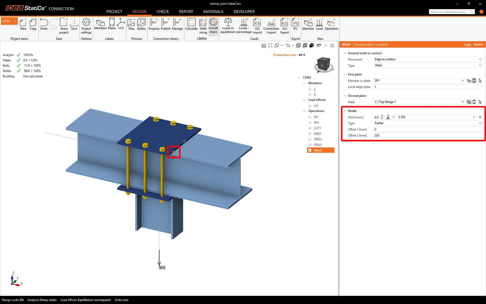
In this case, it is necessary to add a "utility" weld in order to deal with the small shear force. For this, a Partial weld with Offset can be used. The analysis can then be finished, while the impact of the utility weld on the model behavior is negligible.
Material properties are set to 0
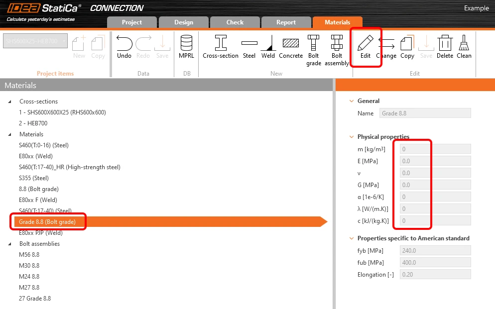
If a material property is filled with 0 (zero) or some non-acceptable value and this material is used in the project, the finite element model can not be calculated, and the analysis stops at 0%. This can be a property of a cross-section, steel material, bolt grade, etc.
Material parameters can be edited in the Materials tab, or possibly imported with a 0 value via a BIM link or CSV file (MPRL database).
Analysis failure due to unconstrained direction in slotted holes
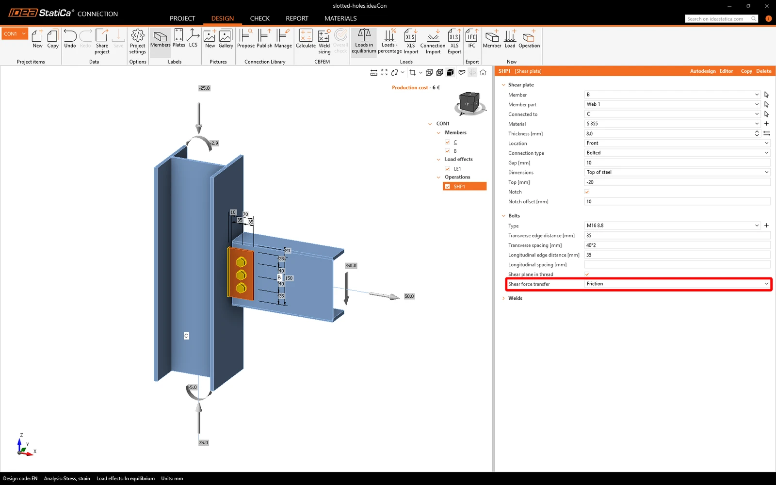
In IDEA StatiCa Connection, bolts in slotted holes exclude resistance along the slot axis, allowing free movement in that direction. If a load or reaction component acts along the slot without a clear restraint, the analysis fails to converge.
To resolve this, model the connection as friction connection with preloaded bolts by setting Shear force transfer to Friction (based on design codes, this is only possible for high-strength bolts suitable for preloading).
Alternatively, since the physical joint permits only a limited range of movement, you can model the bolts using standard circular holes if the slotted release behavior is not intentionally required for your design model. In this case keep in mind that slotted holes reduce shear connection capacity under most design codes (e.g., Eurocode, AISC). Because standard holes will not automatically trigger these code-specific reductions in the software, you must manually check and verify the reduced shear capacity separately.
Lost of stability of hollow section during geometrically nonlinear analysis (GMNA)
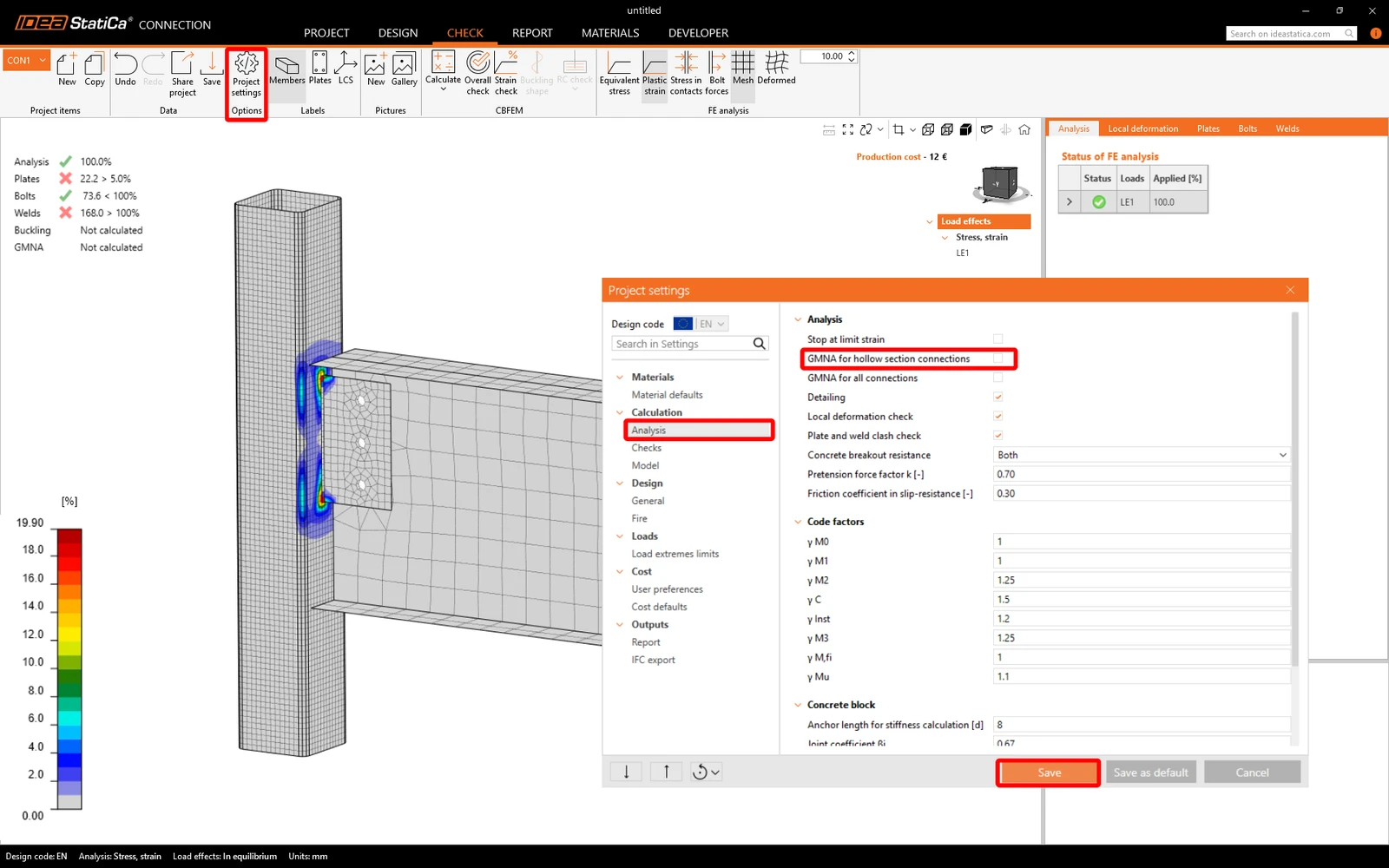
GMNA means advanced geometrically nonlinear analysis, which provides more precise results for models mainly with hollow section members. The GMNA solver is used only when the bearing member has a hollow section. GMNA analysis can be turned on/off in the Project settings.
Note: If the bearing member is not a hollow section, the GMNA solver is disabled for the analysis of the whole connection model regardless of the settings in the code setup (GMNA on or off).
When the connection is overloaded, the hollow sections might lose stability, which results in a break of the analysis at the current percentage of applied loads.
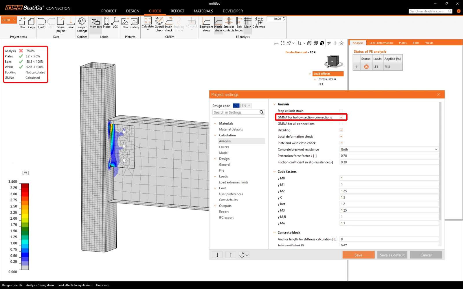
By disabling the GMNA in the Project settings, the analysis finishes with 100%, revealing the failure of the hollow section and other parts of the connections.
Misalignment of finite elements of circular hollow sections
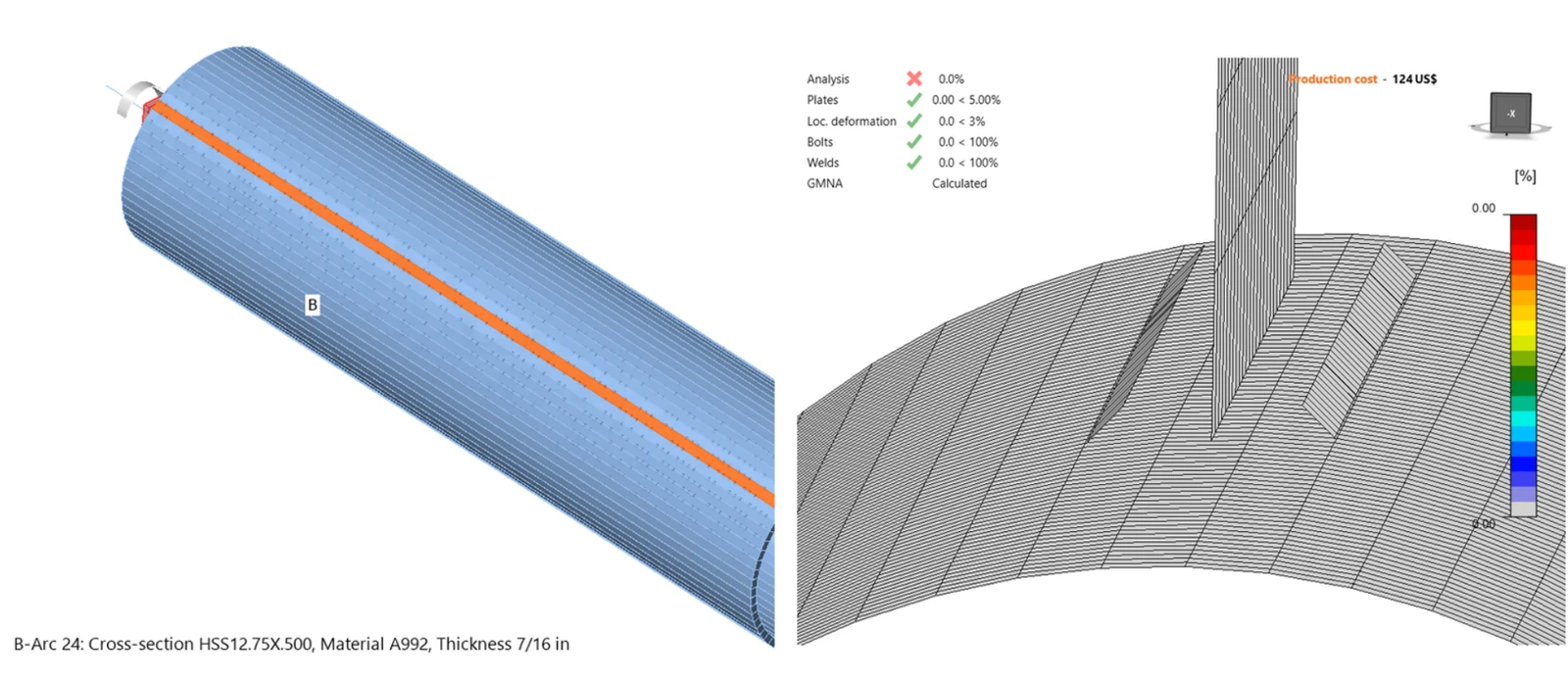
In Connection, CHS members are modeled using plane shell elements which sometimes do not coincide with other mesh lines. This specifically happens when a perpendicular element is connected, or when the Cut operation (using the Mitre cut method) is used to cut and weld members with circular hollow sections.
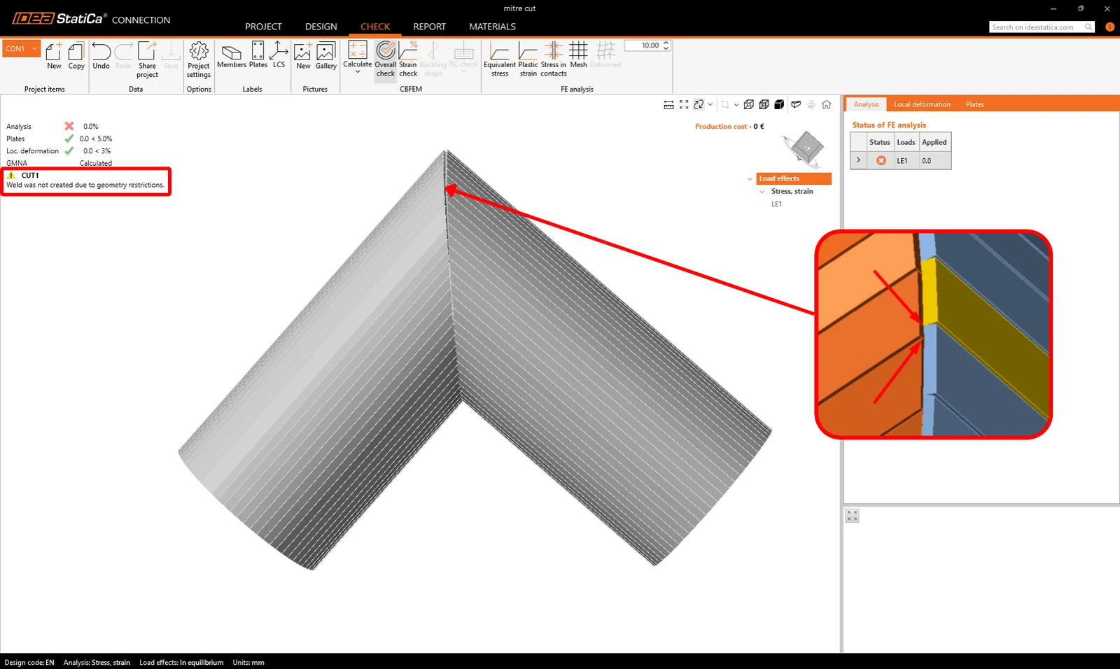
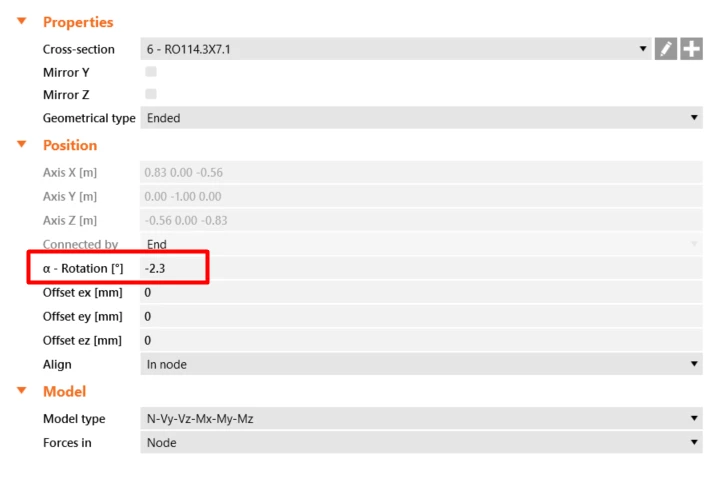
For the cut of hollow sections, changing the α - Rotation value of the one of the connected members helps align the elements so the butt weld can be created. The butt weld is represented by a yellow line, which is visible when the 3D view is switched to transparent mode.
A workaround for the connected perpendicular element is to change the cross-section to a Regular Polygon hollow section from the cold-formed database with a high number of vertices. Too thin elements in the arc segments can coused problem now, but that can be easily solved aditing the Project settings as discrabed in the next paragraph.
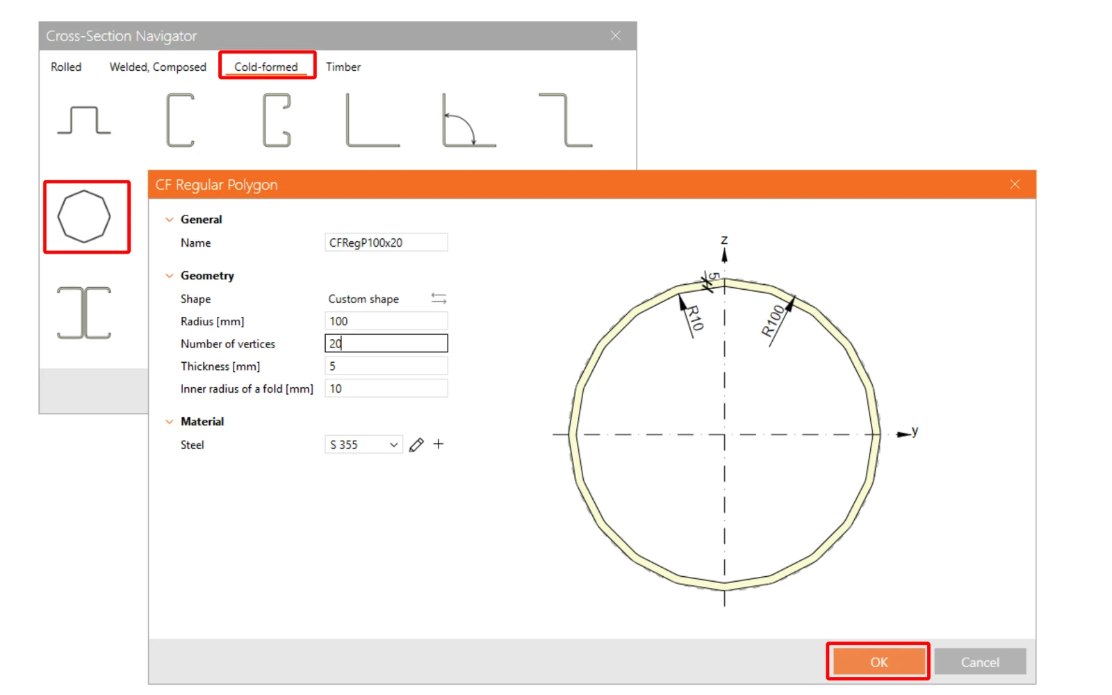
Too thin finite elements in the arc segments of polygonal hollow member
When modelling a members with circular hollow sections defined as polygons, in some cases the calculation may result in the analysis 0% due to the aspect ratio of the finite shell elements in the arc segments of the polygonal hollow member.
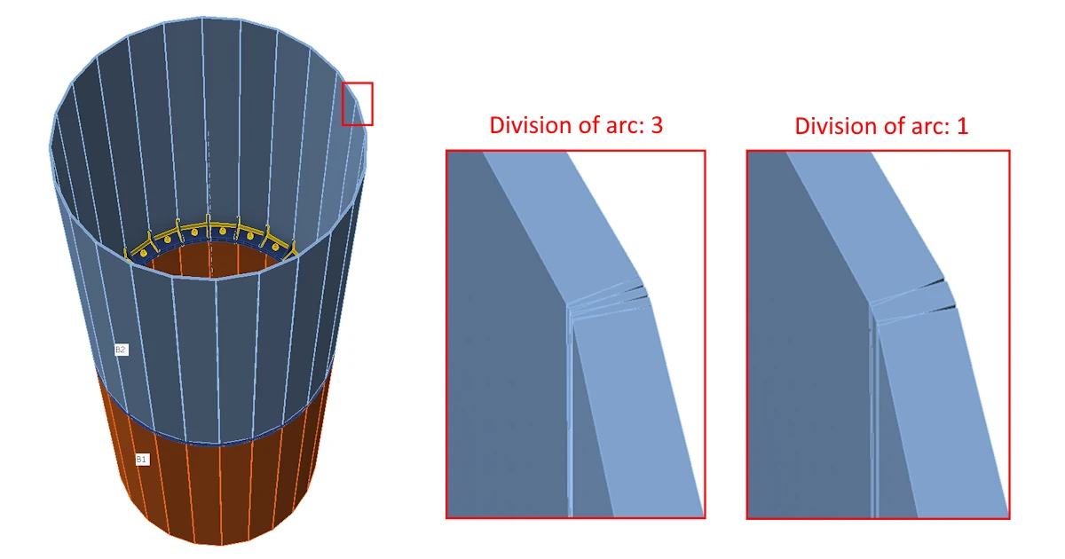
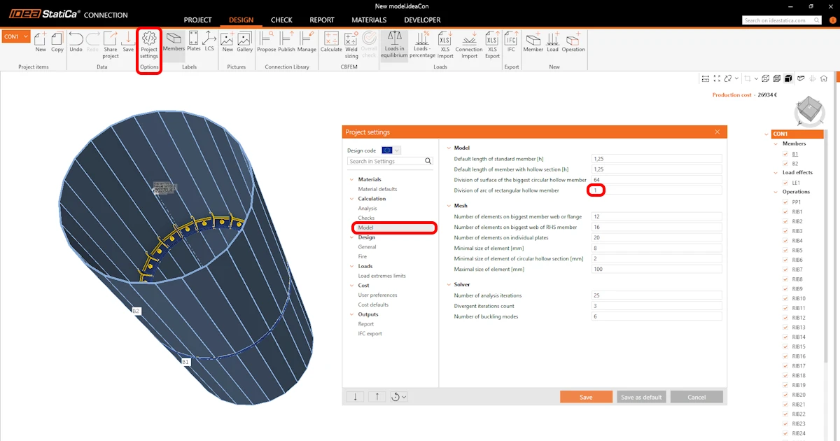
In such cases, in Project settings – Calculation – Model, decrease the value of Division of arc of rectangular hollow member from the default value of 3 to a lower value (e.g. 1). This modification changes the aspect ratio of the finite shell elements in the arc segments of polygonal hollow member.
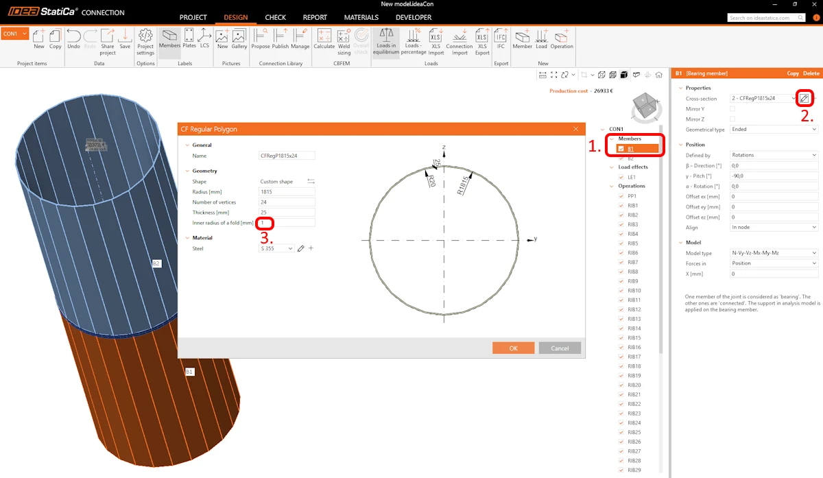
To prevent the generation of shell finite elements in the arc segments of a polygonal hollow member, the user can alternatively decrease the inner radius of a fold to a value of 1 mm when defining the circular hollow section as a polygon (select the relevant member in the Members tree, in the Properties window edit the Cross-section, and set the Inner radius of a fold to 1 mm).
Read more also in the blogs Why did my validation fail? and Troubleshooting IDEA StatiCa Connection models.
Released in IDEA StatiCa version 25.1.