
Columns subjected to high compressive loading – Passive confinement effect
Introduction
The passive confinement effect in concrete structures refers to the phenomenon where the strength and ductility of concrete are significantly improved due to confinement provided by surrounding materials, such as steel reinforcement or external jackets. This effect is particularly important in enhancing the performance of concrete in compression, especially under high loads.
Here are the key aspects of the confinement effect in concrete structures:
- Increased strength: Confinement increases the compressive strength of concrete. When lateral pressure is applied, it restrains the lateral expansion of the concrete, allowing it to sustain higher axial loads before failing.
- Enhanced ductility: Confined concrete exhibits greater ductility, meaning it can undergo larger deformations before failure.
- Mechanisms of passive confinement:
- Internal confinement: Achieved through transverse reinforcement such as ties, stirrups, or spirals within reinforced concrete. These reinforcements prevent the concrete from cracking and bulging outward.
- External confinement: Involves the use of external materials like fiber-reinforced polymer (FRP) wraps, steel jackets, or concrete jackets applied around the structural member. This method is often used for retrofitting and strengthening existing structures.
- Behavior under load: Confinement changes the failure mode of concrete from a brittle, sudden failure to a more ductile, gradual one. This change in failure mode is beneficial for the safety and integrity of structures under extreme loading conditions.
- Design considerations: The design of confined concrete members involves calculating the amount and arrangement of confining reinforcement to achieve the desired strength and ductility. Standards and codes, such as EN (Eurocode) guidelines, provide formulas and guidelines for designing confined concrete elements.
- Applications: Confinement is widely used in the design of columns, bridge piers, and other critical structural elements. It is also used in retrofitting and strengthening existing structures to improve their load-carrying capacity.
In the following figure, you can observe how the stress-strain diagram and bearing capacity can differ for unconfined and confined concrete.
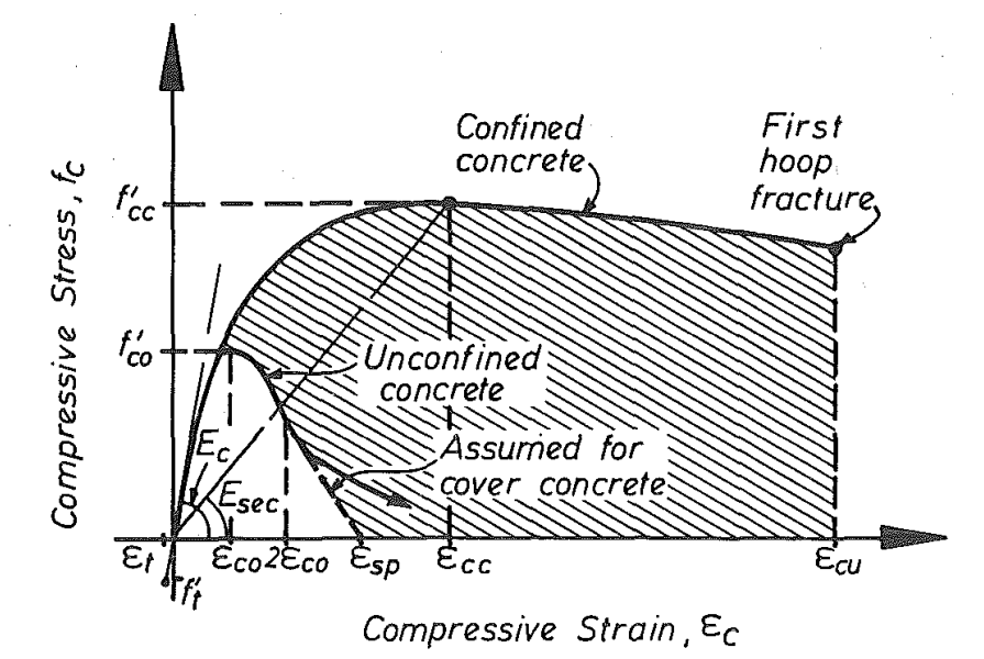
\[ \textsf{\textit{\footnotesize{Fig. 1\qquad Stress-strain model proposed for monotonic loading of confined and unconfined concrete [2]}}}\]
Columns subjected to high compressive loading – a passive confinement example
In this example, we compare several differently shaped columns subjected to high compressive loading with different topologies and reinforcement ratios, calculated in IDEA StatiCa Detail and calculated by different analytical approaches by Morger, et al. [1], which are given in several current standards – fib Model Code for Concrete Structures 2010 (MC 2010) [3], SIA 262:2013 Concrete Structures (SIA 262) [4], and Eurocode 2 - Design of concrete structures EN 1992-1-1:2023 (EC 2) [5].
Before we get into the verification itself, let's recall the theoretical basics of 3D CSFM implemented in the application IDEA StatiCa Detail – Structural design of concrete 3D discontinuities in IDEA StatiCa Detail
Analytical methods
The whole verification is based on the analytical approaches already mentioned in [1]. In this text, we will only give a basic description of the analytical methods of calculation including the relevant formulas. For a better understanding, we recommend studying the paper [1] in more detail.
The load-bearing resistance of an RC member in compression can be obtained by summing up the three individual components with their associated cross-sectional areas: (i) the uniaxial concrete compressive strength of the entire concrete cross-section, (ii) the compressive strength of the longitudinal reinforcement, and (iii) the increase in concrete compressive strength due to a triaxial stress state provided by confining reinforcement:
\[N_{R}=\underset{(i)}{\underbrace{f_{c}\cdot A_{c}}}+\underset{(ii)}{\underbrace{(f_{sy.l}-f_{c})\cdot A_{s.l}}}+\underset{(iii)}{\underbrace{\Delta f_{conf}\cdot A_{conf}}}\]
where fc = uniaxial concrete compressive strength, Ac = concrete cross-section area, fsy,l and As,l = yield strength and total cross-sectional area of longitudinal reinforcement, Δfconf = concrete compressive strength increase due to confinement, and Aconf = governing confined concrete area.
In this article, the coordinate system of an RC member in compression is chosen such that the loading direction coincides with the x-axis, which is referred to as the longitudinal direction. The y and z-directions are, thus, referred to as lateral directions.
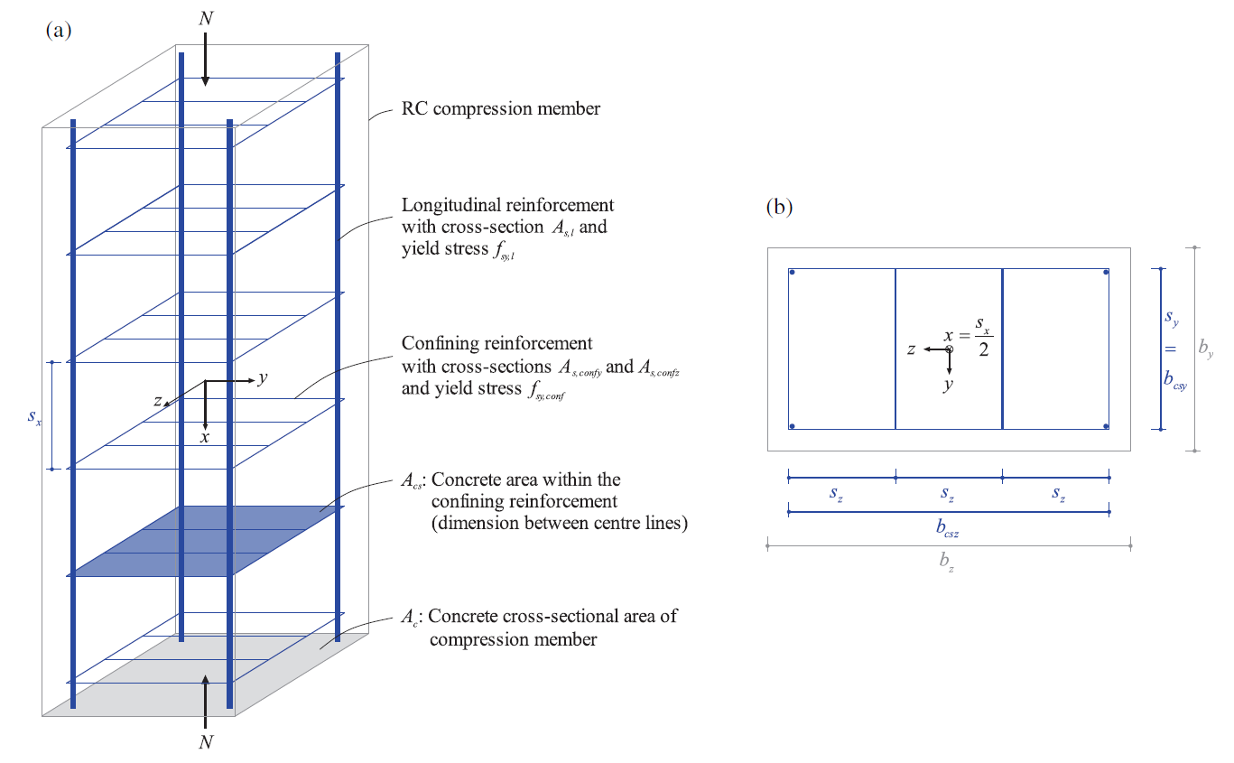
\[ \textsf{\textit{\footnotesize{Fig. 2\qquad Definition of most important geometrical parameters [1]}}}\]
The increase of the concrete compressive strength Δfconf due to confinement is approximately four times the lateral compressive stress [6].
\[\Delta f_{conf}=4\cdot min(\sigma_{confy},\sigma_{confz})\]
Assuming yielding of the confining reinforcement and full dispersion of the confining forces, the confining stresses follow equilibrium as:
\[\sigma_{confy}=\frac{\sum A_{s.confy}\cdot f_{sy.conf}}{s_{x}\cdot b_{csz}};\sigma_{confz}=\frac{\sum A_{s.confz}\cdot f_{sy.conf}}{s_{x}\cdot b_{csy}}\]
Where fsy.conf is the yield strength of confining reinforcement.
The following sub-sections present the different existing approaches to determine the governing confined concrete area Aconf (and the corresponding effectiveness factor k) according to current design guidelines (EC 2, SIA 262, and MC 2010) and according to a new model approach for passive confinement presented in [1].
Design approaches according to design guidelines
EC2 determines the governing confined concrete area Aconf,EC2 based on arching action between the discretely distributed load introduction points of the confining reinforcement.
\[A_{conf.EC2}=\underset{A}{\underbrace{\left( b_{csy}\cdot b_{csz}-\frac{\sum s^{2}_{i}}{6}\right)}}\cdot \underset{B}{\underbrace{\left( \frac{(b_{csy}\cdot s_{x}/2)\cdot(b_{csz}-s_{x}/2)}{b_{csy}\cdot b_{csz}}\right)}}\]
\[= \left( b_{csy}\cdot b_{csz}-\frac{\sum s^{2}_{i}}{6}\right) \cdot \left(1-\frac{s_{x}}{2\cdot b_{csy}} \right) \cdot \left(1-\frac{s_{x}}{2\cdot b_{csz}} \right)\]
This equation, applicable to rectangular crosssections, is based on the work of Mander [2]. For more information and an understanding of parts A and B, refer to [1].
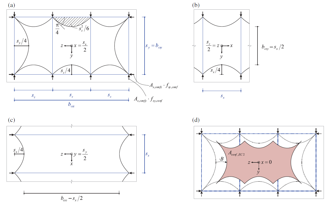
\( \textsf{\textit{\footnotesize{Fig. 3\qquad Definition of confined concrete area according to EC 2: (a) confined concrete area at the section of a confining }}}\) \( \textsf{\textit{\footnotesize{reinforcement layer (e.g., x = sx/2), (b) and (c) longitudinal dispersion of confining forces, (d) governing confined concrete }}}\) \( \textsf{\textit{\footnotesize{area at the center between two confining reinforcement layers (e.g., x=0, dotted lines indicating section from (a) as reference).}}}\)
It is worth mentioning that in EC2, the effectiveness factor of the confining reinforcement k is used to express the load-bearing resistance. Factor k is the ratio between the governing confined concrete area Aconf and the cross-sectional area Ac.
\[k=\frac{A_{conf}}{A_{c}}\]
Using this factor, the load-bearing resistance NR can be rewritten as:
\[N_{R}=\left( f_{c}+k\cdot \Delta f_{conf}\right)\cdot A_{c}+(f_{sy.l}-f_{c})\cdot A_{s.l}\]
The effective factor is then defined as:
\[k=\left(\frac{b_{csy}\cdot b_{csz}-\frac{1}{6} \sum b_{i}^{2}}{b_{cy}\cdot b_{cz}}\right)\cdot \left(1-\frac{s_{x}}{2\cdot b_{csy}} \right)\cdot \left(1-\frac{s_{x}}{2\cdot b_{csz}} \right)\]
For the purposes of this article, however, we will stick to the load-bearing resistance NR expression from the beginning of the chapter over the use of the governing confined concrete area Aconf.
SIA 262 defines the governing confined concrete area Aconf,SIA262 based on the stress field illustrated in Figure 4, proposed by Sigrist [7].
\[A_{conf.SIA262}=(b_{csy}-s_{x})\cdot (b_{csz}-s_{x})\]
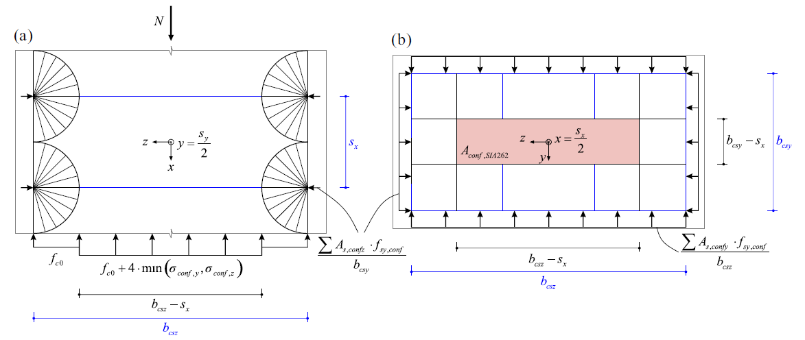
\( \textsf{\textit{\footnotesize{Fig. 4\qquad Definition of the confined concrete area according to SIA 262: (a) stress field and (b) lateral section at the level }}}\) \( \textsf{\textit{\footnotesize{of the confining reinforcement (e.g., x = sx/2). }}}\)
MC 2010 defines the governing confined concrete area as a combination of the two models forming the basis of the EC 2 and SIA 262 formulation:
\[A_{conf.MC2010}=\left( b_{csy}\cdot b_{csz}-\frac{\sum s^{2}_{i}}{6}\right)\cdot \left( \frac{(b_{csy}\cdot s_{x})\cdot(b_{csz}-s_{x})}{b_{csy}\cdot b_{csz}}\right)\]
\[= \left( b_{csy}\cdot b_{csz}-\frac{\sum s^{2}_{i}}{6}\right) \cdot \left(1-\frac{s_{x}}{b_{csy}} \right) \cdot \left(1-\frac{s_{x}}{b_{csz}} \right)\]
The new model approach for passive confinement introduced in [1] defines the simplified confined concrete area Aconf,simp as a function of the confining reinforcement geometry and spacing.
\[A_{conf.simp}=\left(b_{csy}-\frac{\sqrt{s_{x}^{2}+s_{z}^{2}}}{2}\right)\cdot \left(b_{csz}-\frac{\sqrt{s_{x}^{2}+s_{y}^{2}}}{2}\right)\]
IDEA StatiCa Detail models
Models are of the solid block type with various plan dimensions bcy x bcz, height hx, and stirrups distance sx made of C30/37 concrete supported by rigid surface support in the X, Y, Z direction at the bottom surface. For the sake of the stability of the top concrete cover in the model, the top surface is also supported in horizontal directions by rigid support. Concrete cover c is 30 mm for all models. There are always four longitudinal rebars with the diameter Φs,l = 10 mm. Stirrups, the confining reinforcement, and longitudinal bars are modeled from steel B500B. All calculations are in characteristic values.
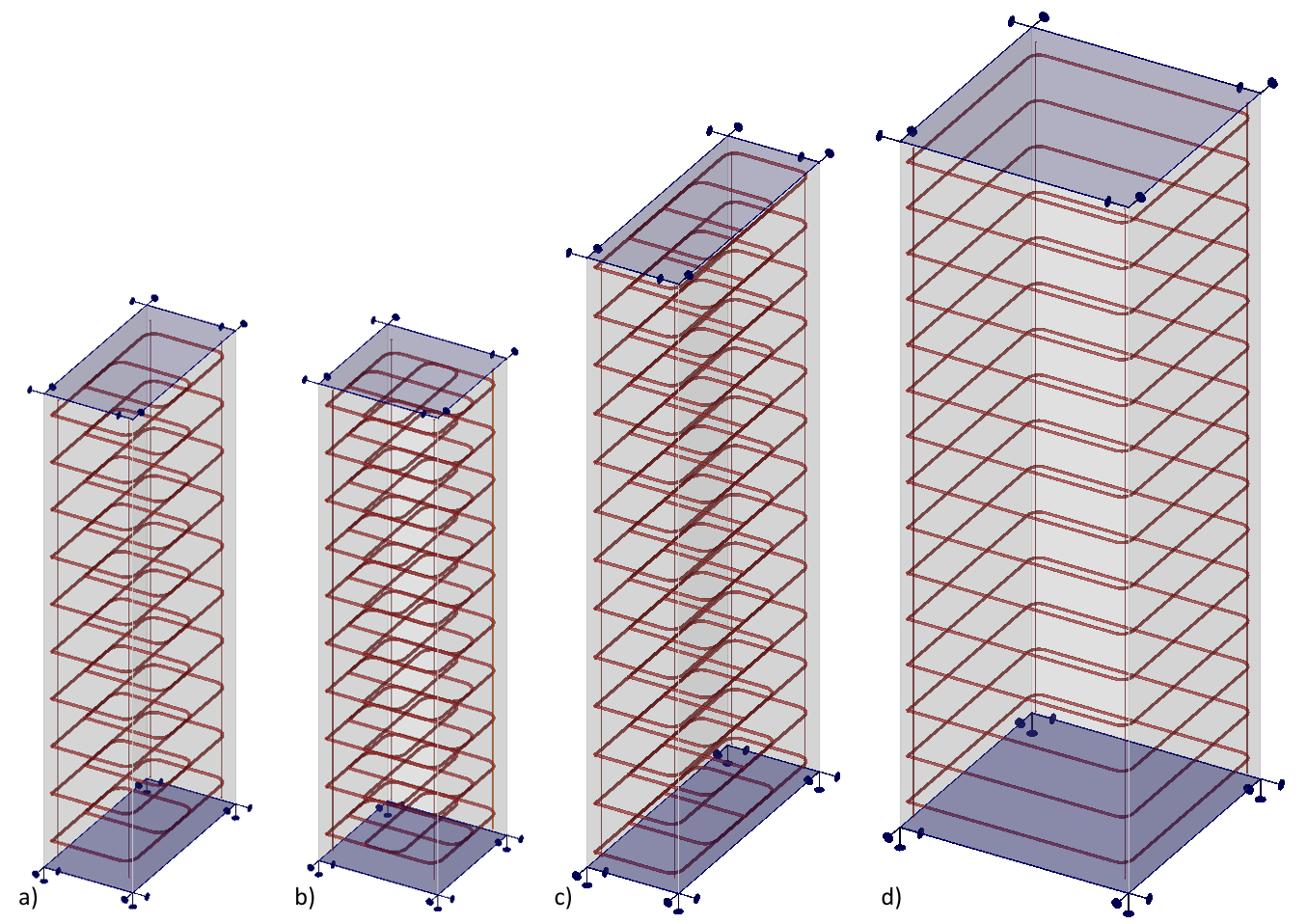
\[ \textsf{\textit{\footnotesize{Fig. 5\qquad IDEA StatiCa Detail models a) 0.75 x 1.5 x 4.0; b) 1.0 x 1.0 x 4.0; c) 0.75 x 2.5 x 5.0; d) 2.0 x 2.0 x 6.0}}}\]
A load greater than the expected load capacity is always applied. The program then searches for the maximum possible applicable load so that one of the defined criteria is not exceeded. In this case, it is always the limit strain criterion of the stirrup reinforcement, which is a maximum of 5%, but due to the implemented Tension stiffening, the limiting value is usually lower. For more details, see Theoretical Background.
In the following figure, it can be seen that the calculation of model 0.75 x 1.5 x 4.0 was stopped and a multiple of the applied load was found as the maximum load that the element can resist.
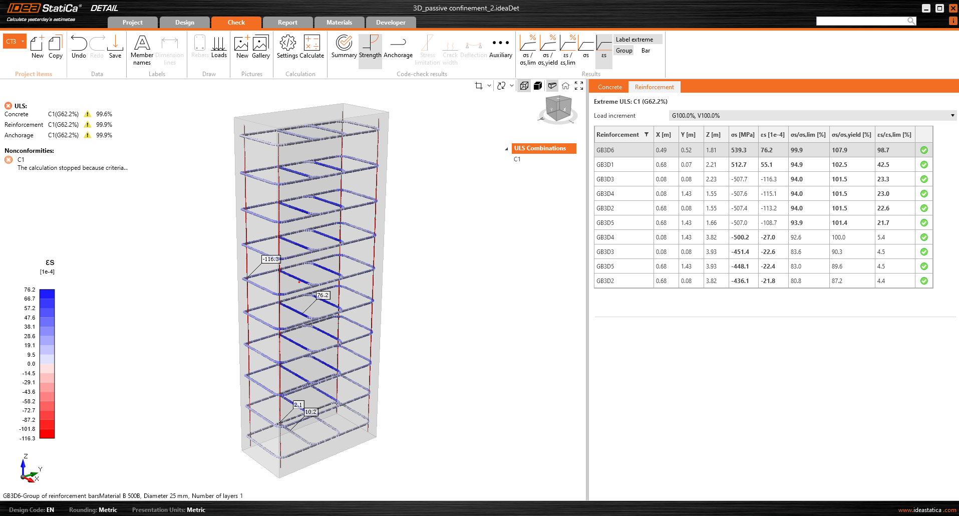
\[ \textsf{\textit{\footnotesize{Fig. 6\qquad IDEA StatiCa Detail – limit strain in reinforcement}}}\]
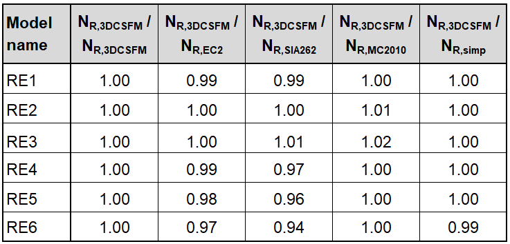
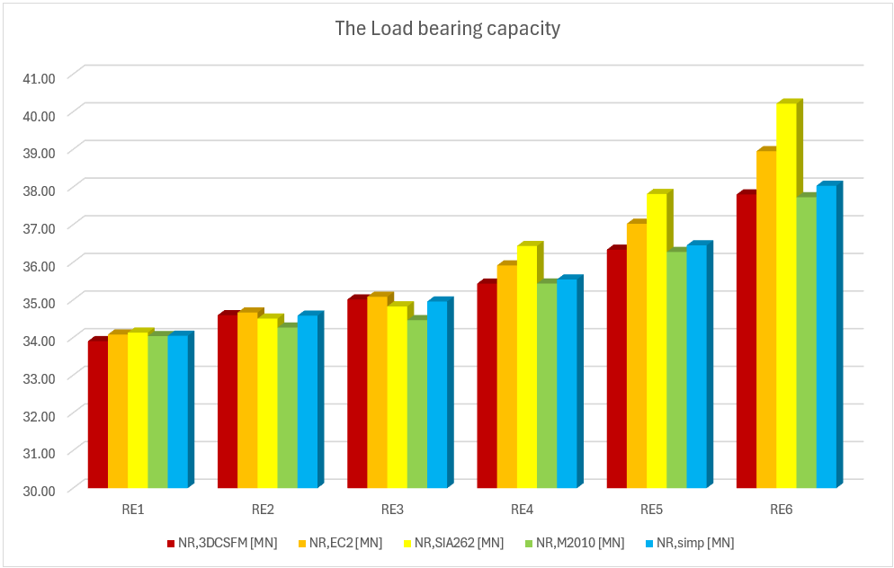
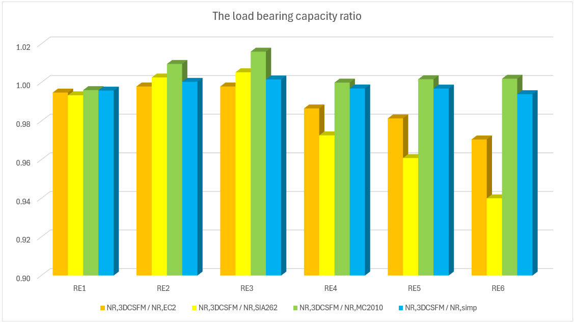
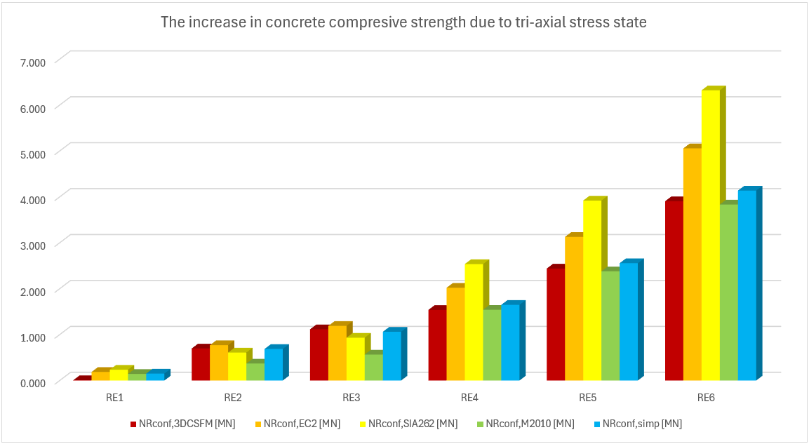
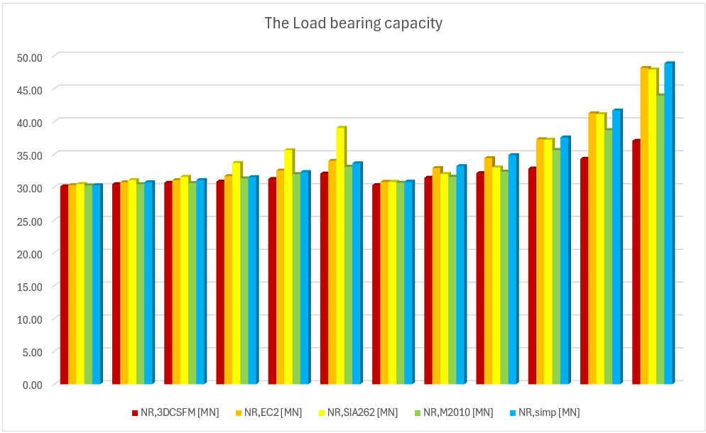
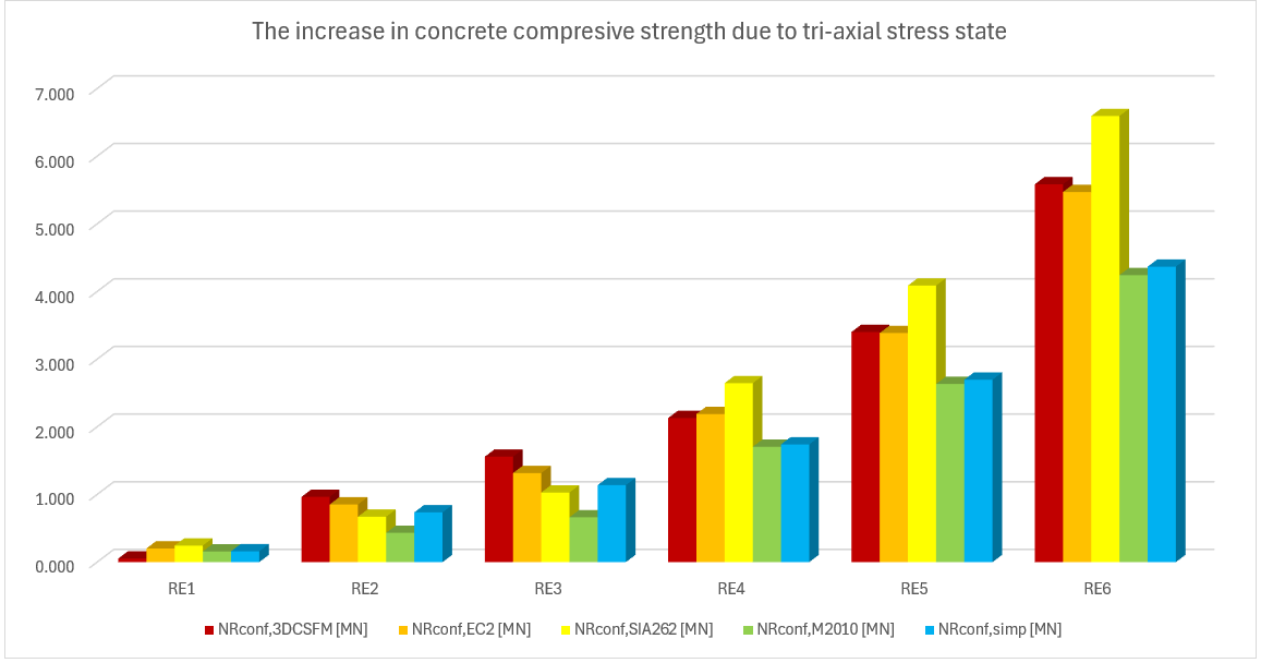
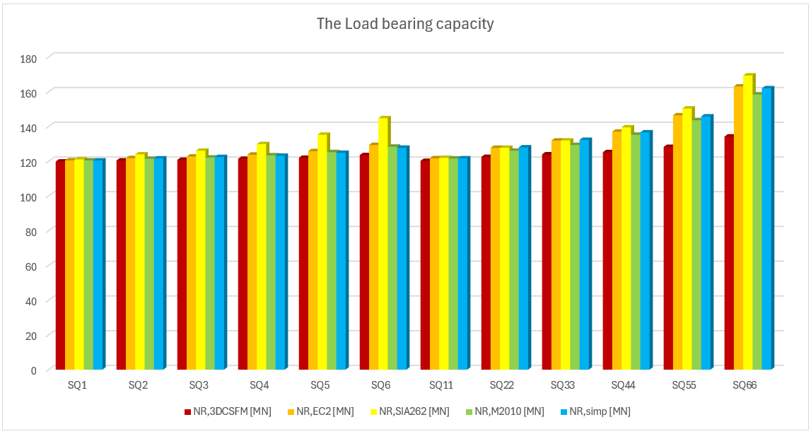
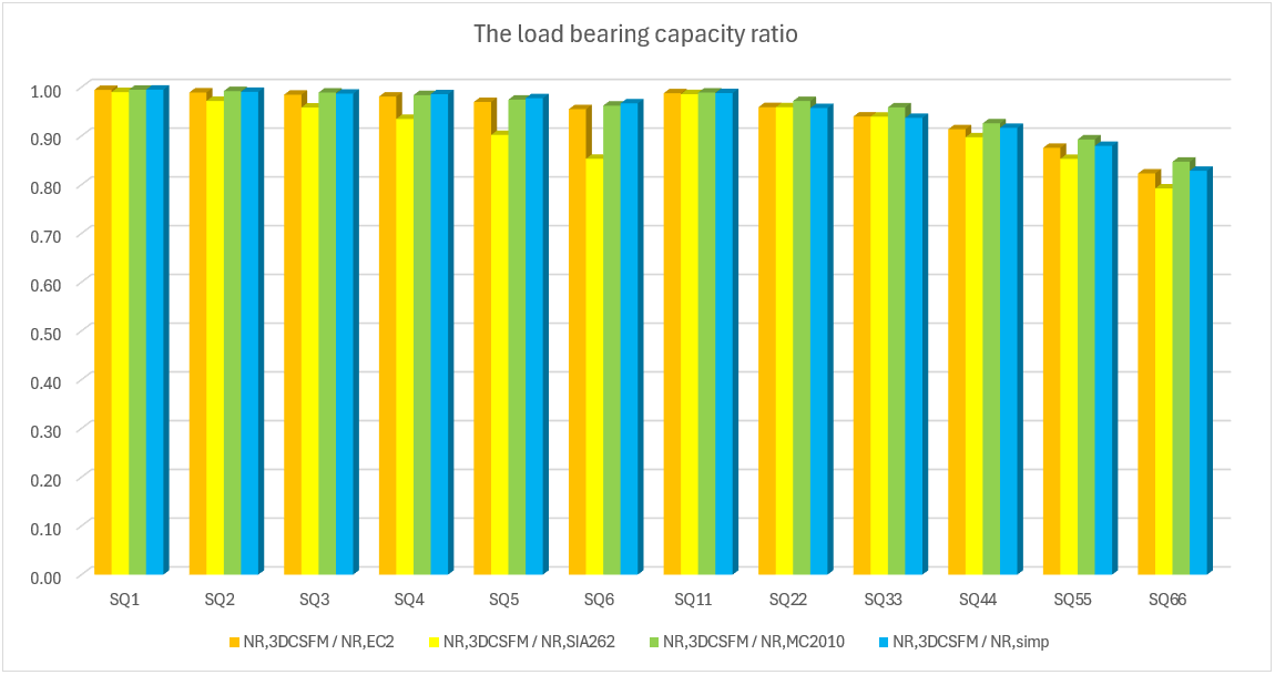
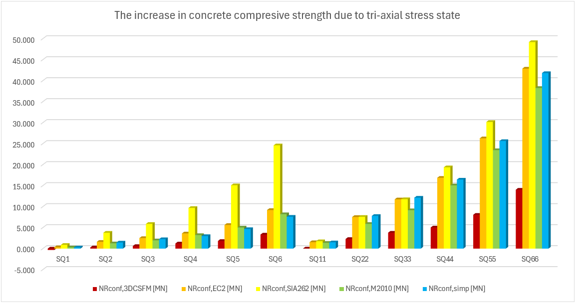
Comparison of individual models
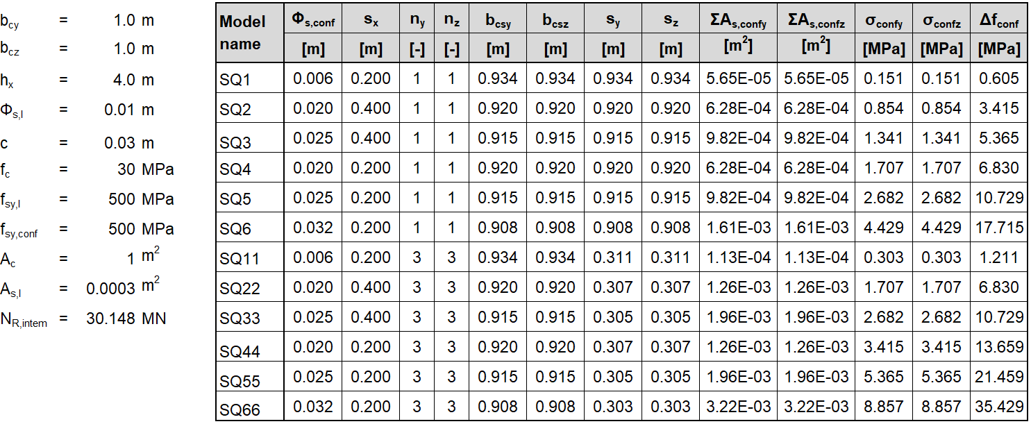
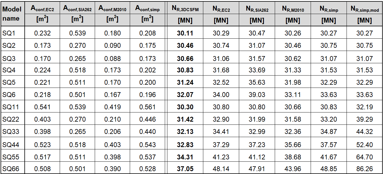
In the following tables and graphs, we present a comparison of all models created in the IDEA StatiCa Detail application and analytical approaches, including all intermediate results for one rectangular and one square model. However, there are auxiliary variables that need to be defined first.
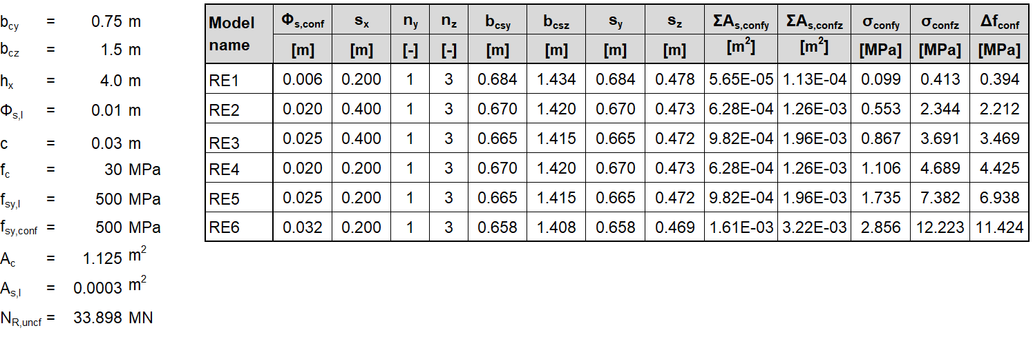
Φs,l and Φs,conf are the diameters of longitudinal and confining reinforcement, ny and nz are the numbers of spaces sy and sz (meaning that the number of stirrup legs is n+1), NR,uncf and NR,conf are defined as follows:
\[N_{R,uncf}=f_{c}\cdot A_{c}+(f_{sy.l}-f_{c})\cdot A_{s.l}; N_{R,conf}=\Delta f_{conf}\cdot A_{conf}\]
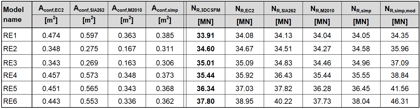
Rectangular model a) 0.75 x 1.5 x 4.0
Square model b) 1.0 x 1.0 x 4.0
Rectangular model c) 0.75 x 2.5 x 5.0
Square model d) 2.0 x 2.0 x 6.0
Conclusion
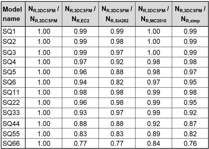
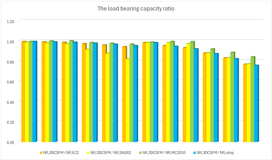
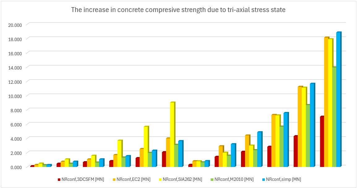
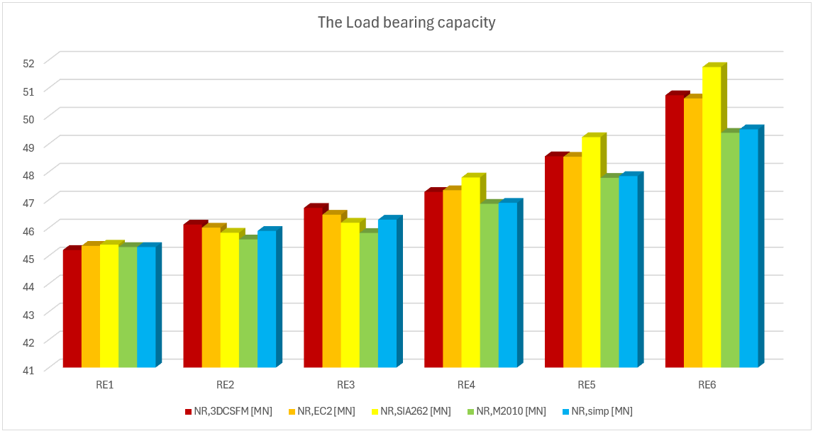
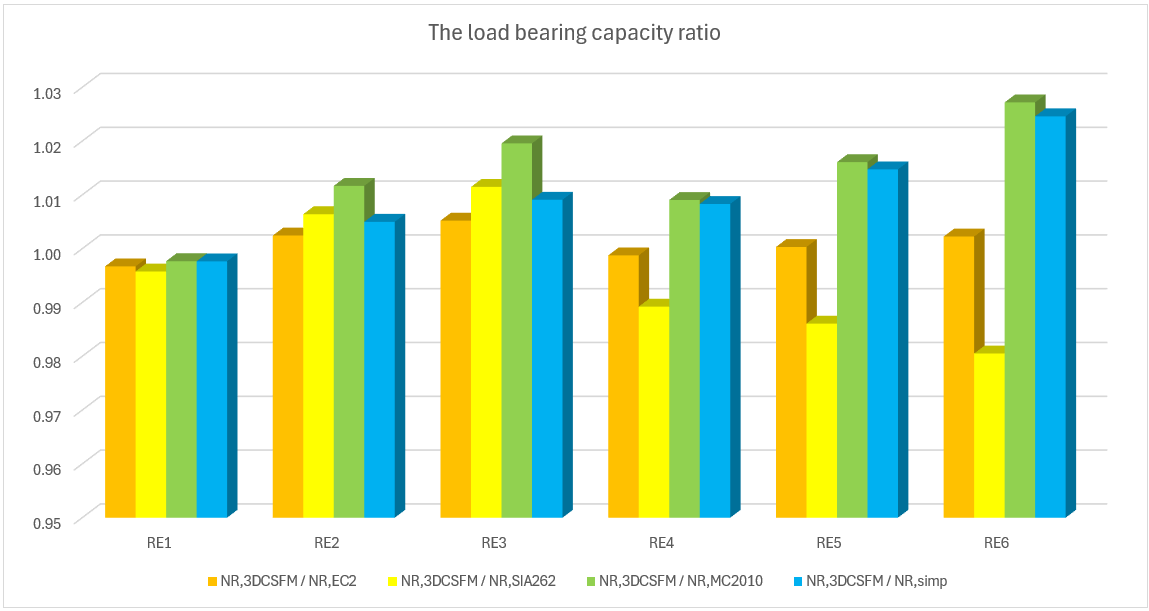
Several conclusions can be drawn from the results presented above. In general, the 3D CSFM results have been shown to be quite conservative, especially for square models where the increase in load capacity due to the confinement is less than half in some examples. Good conformity, within 2% deviation, can be observed for rectangular models. Among the analytical methods investigated, the EC2 approach shows the best match in all models. This verification demonstrates that the use of 3D CSFM is safe from a passive confinement point of view and in accordance with the established methods of standards.
References
[1] MORGER, Fabian; KENEL, Albin a KAUFMANN, Walter. Passive confinement of reinforced concrete members revisited. Online. Structural Concrete. ISSN 1464-4177. https://doi.org/10.1002/suco.202400209.
[2] Mander JB, Priestley MJN, Park R. Observed stress-strain behavior of confined concrete. J Struct Eng. 1988;114:1827–49. https://doi.org/10.1061/(ASCE)0733-9445(1988)114:8(1827)
[3] International Federation for Structural Concrete (fib). Model code for concrete structures 2010; 2013.
[4] SIA. Swisscode SIA 262: concrete structures. Zurich, Switzerland: Swiss society of engineers and architects (SIA); 2013.
[5] EN 1992-1-1:2023. Eurocode 2—Design of concrete structures—Part 1-1: General rules and rules for buildings, bridges and civil engineering structures; 2023.
[6] Nielsen MP, Hoang LC. Limit analysis and concrete plasticity. 3rd ed. Boca Raton, FL: CRC Press; 2011. https://doi.org/10.1201/b10432
[7] Sigrist V. Zum Verformungsvermögen von Stahlbetonträgern [On the deformation capacity of structural concrete girders]. Doctoral Thesis. ETH Zürich; 1995. https://doi.org/10.3929/ethz-a-001492371