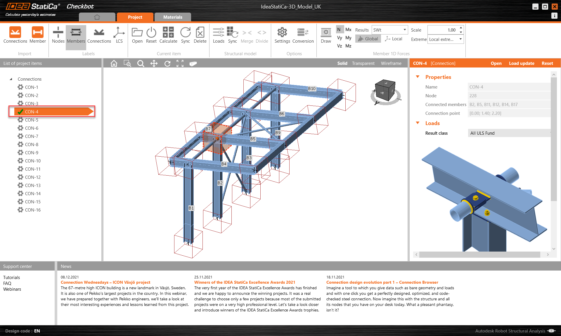
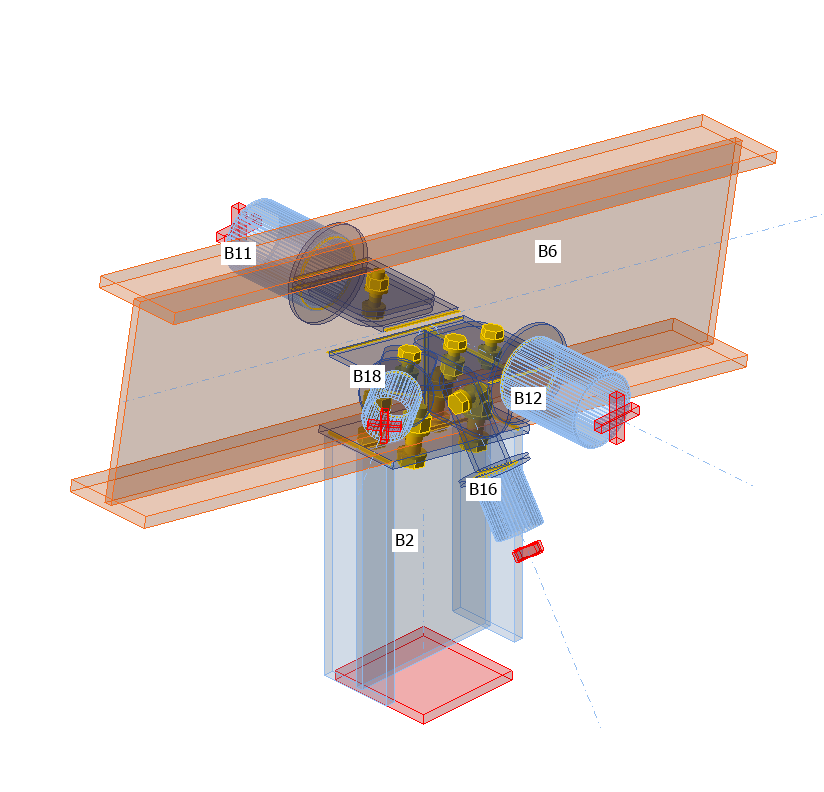
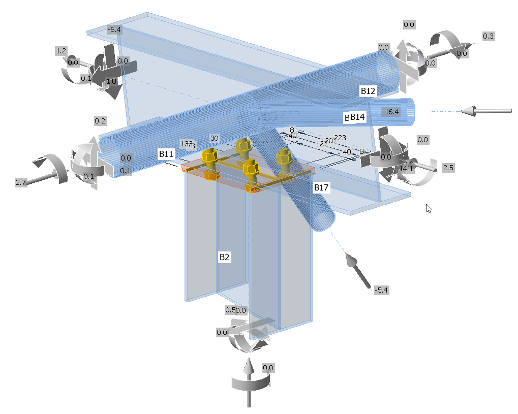
This is the connection to be designed.
If the required node and associated members have not yet been imported into Checkbot then do this now.
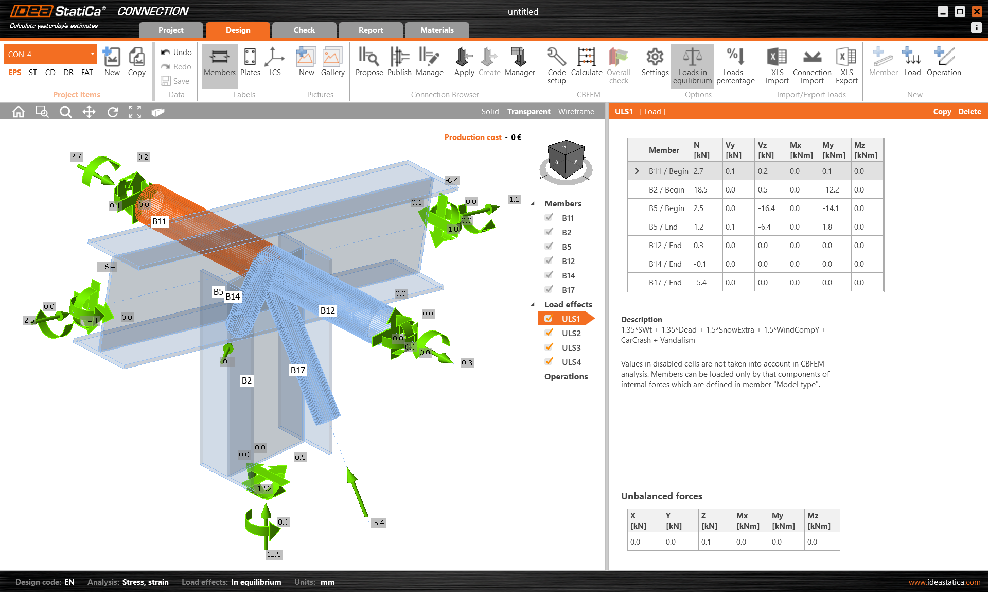
Open this connection. Just as before the member and their load effects are all present and correct.
Column to rafter
Apply a bolted endplate operation from the column to the rafter using the parameters shown below:
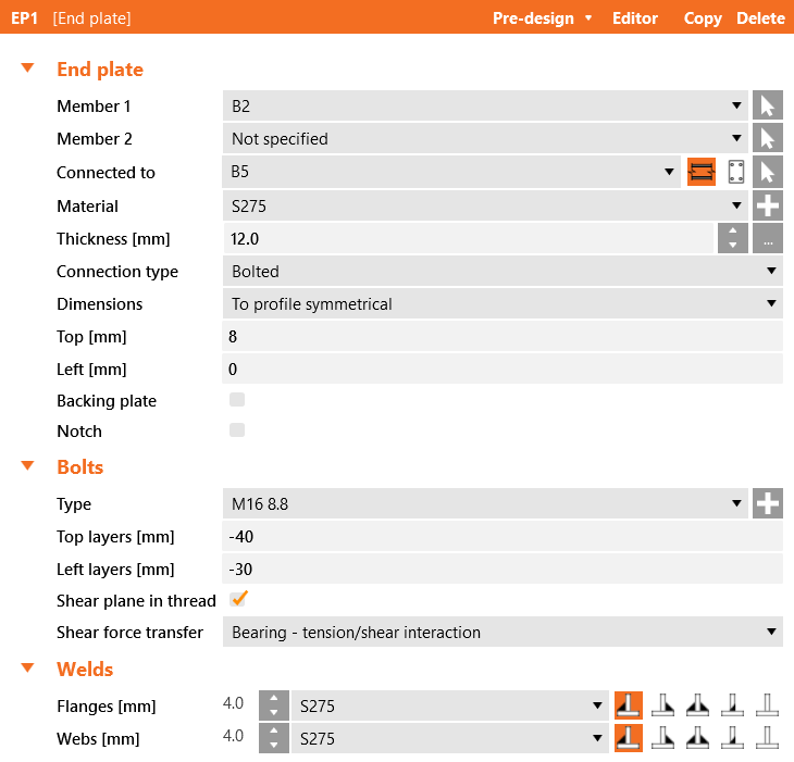
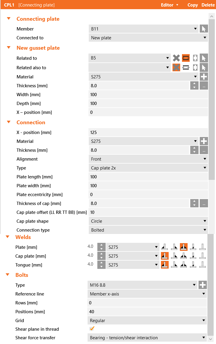
This is what the initial connection looks like:
Main brace to rafter connection
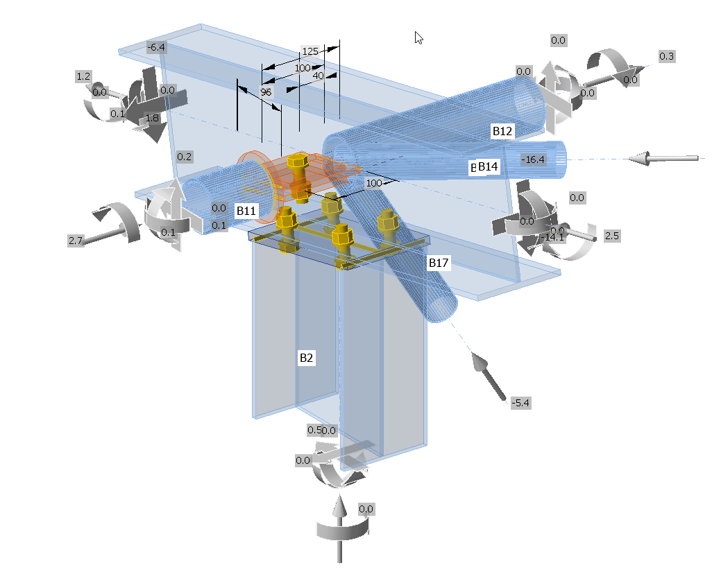
Apply a connecting plate from the brace to the rafter using the parameters below:
This is what the connection should look like after the second operation:
This is a single bolt connection and as such cannot carry moment. To make this a legitimate connection the analysis model for the member must be changed to N-Vy-Vz. This modification should also apply to the other braces.
The plates (tongue and gusset) should be further modified to have 20 mm roundings on the relevant corners.
The other side of the rafter is slightly more complex as there are three members that need to be considered.
Main brace to rafter
Apply a connecting plate from the main brace to the rafter using the parameters below:
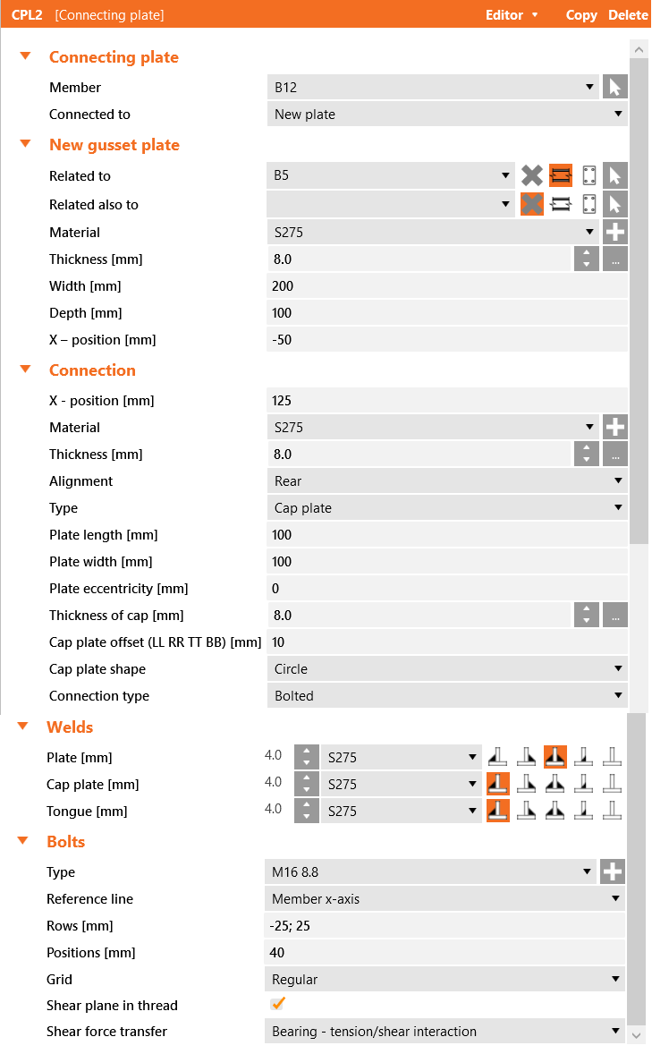
These values will replicate the tongue plate from the other side. We will come back to the gusset plate modifications after the next connection.
Roof diagonal bracing to rafter
Apply a connecting plate to the end of the brace and utilize the existing plate from the previous connection. Refer to the parameters below:
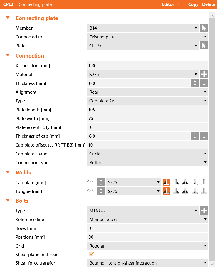
The tongues from both connections should have the same 20mm roundings. The gusset should be modified as shown below:
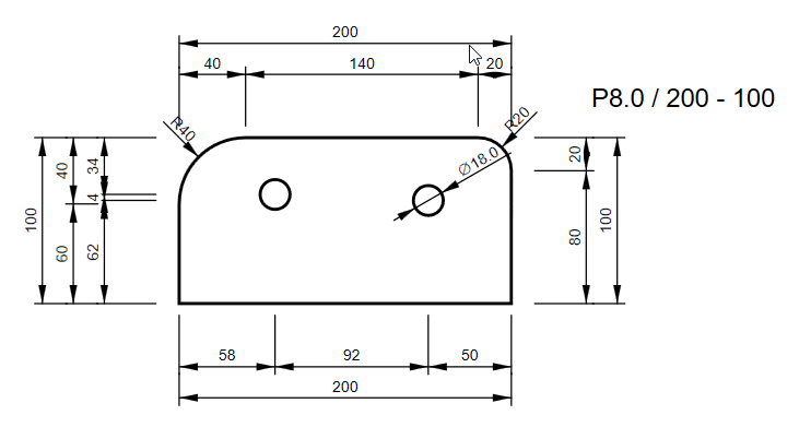
One corner should have a 40mm rounding and the other 20mm.
Vertical diagonal brace connection
This connection will comprise of a stiffening plate, a connecting plate and two plate cuts.
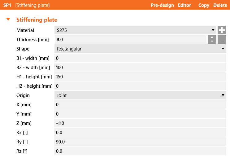
The stiffening plate is as described below:
The connecting plate:
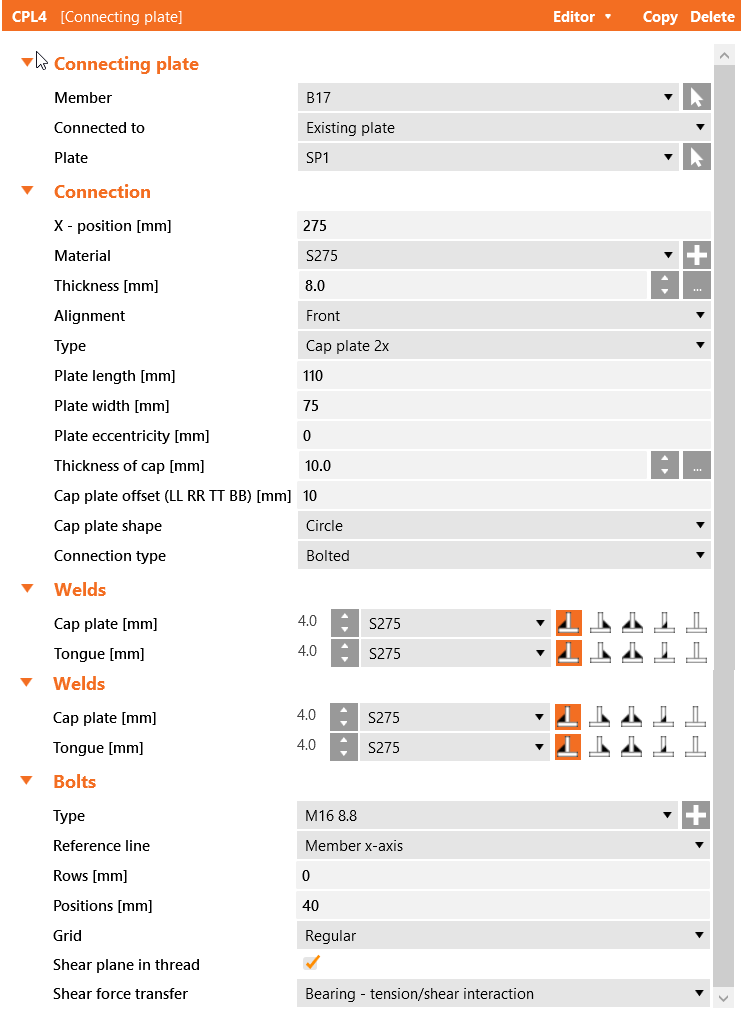
The connecting plate will connect to the existing stiffening plate that was created previously. Apply 20mm roundings to the tongue of this connection.
The stiffening plate can be modified with a rounding as shown below:
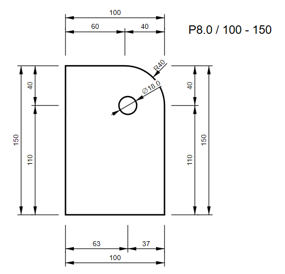
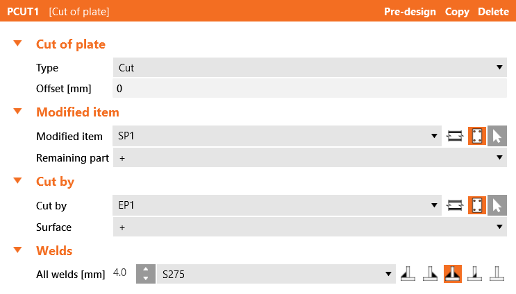
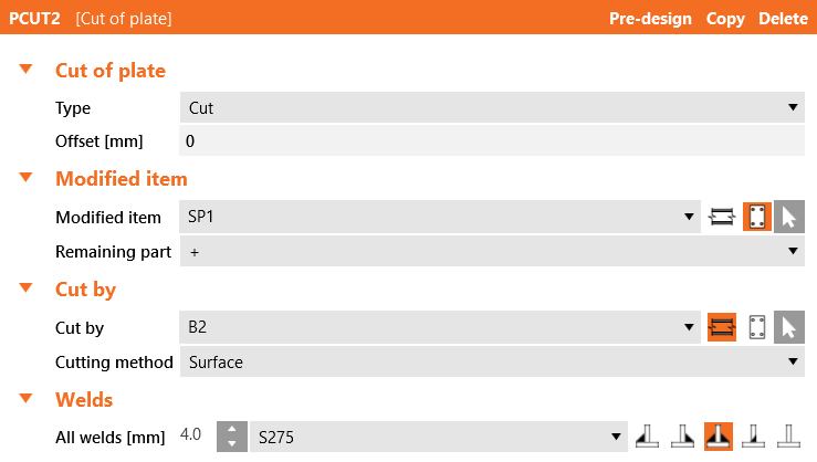
Plate cuts to the cap plate of the column and the column itself complete the connection.
That completes the connection for the top of the column.
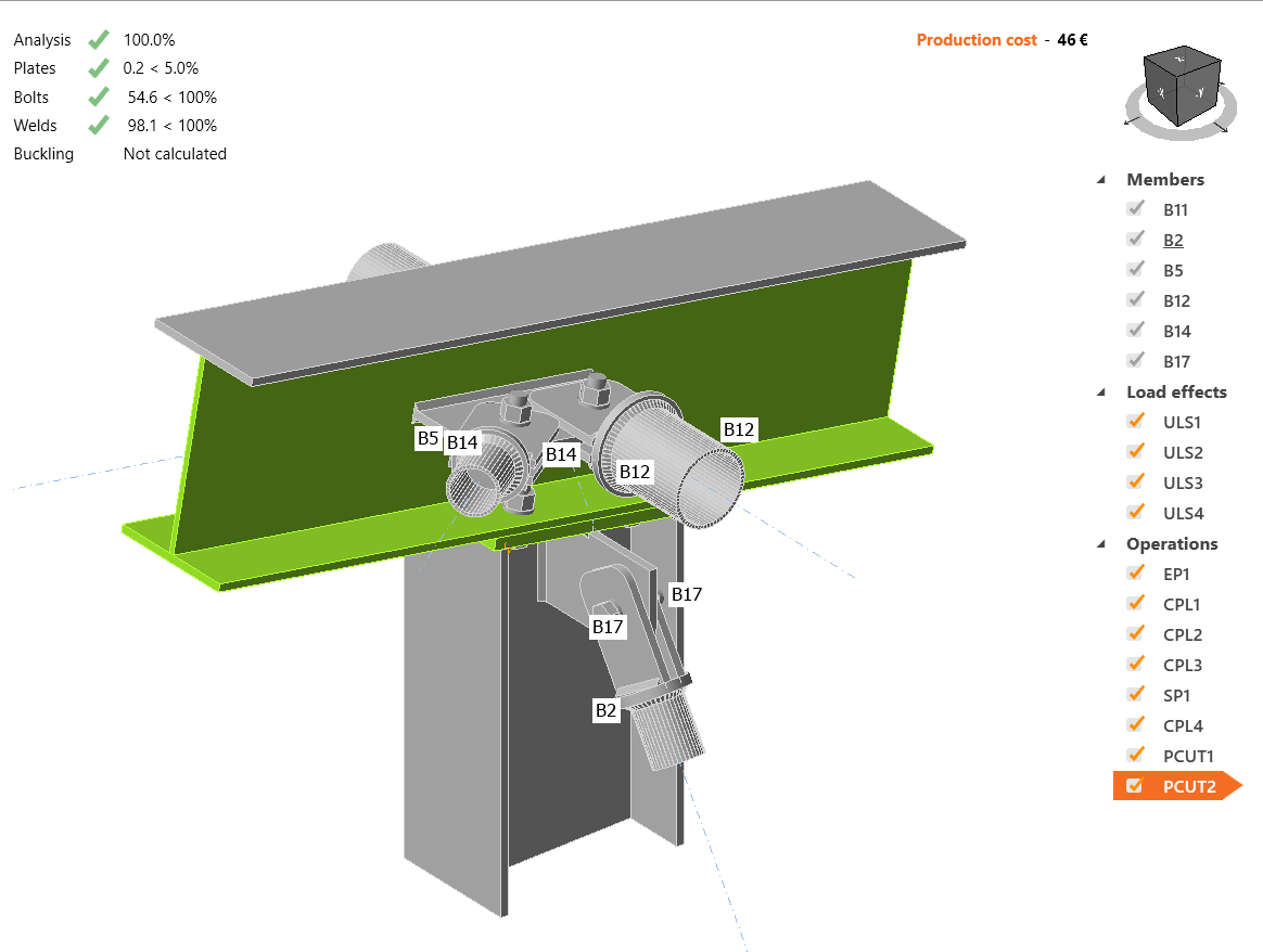
Calculate, Save and Exit this connection back to Checkbot.
You will see that there is a green tick next to the connection. This means that the connection is valid and has passed its code checks.