
Environment and code-checks aligned with ACI
Terminology and Code-checks align with ACI
Modifications include adjusted default coefficients, a revised serviceability design approach, and a clearer distinction between long- and short-term checks. The methodology for creep and the stress-strain diagram now accounts for long-term serviceability loads. More details below:
- α1 coefficient for calculation of concrete limit strength
ACI 318-19 uses a parabolic stress-strain diagram with a decreasing plastic branch for concrete, while Detail applies a diagram with a horizontal plastic branch. To align with ACI 318-19, the concrete’s limit strength can be adjusted using the α1 factor, resulting in a parabola-rectangle stress-strain diagram. This coefficient is set in Project settings, either by code or as user input. When defined by code, its value follows ACI 318-19 Section 22.2. The concrete strength is then calculated as: f'c,lim = α1 * Φc * ηfc * kc2 * fc'
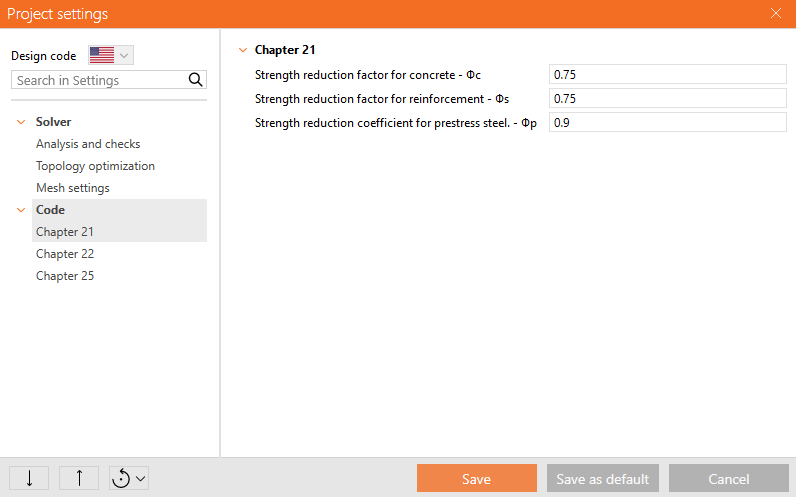
- Change default strength reduction factor values
Most models in Detail are expected to be shear-controlled or involve corbels and brackets. Therefore, the default coefficients have been set to 0.75 per ACI 318-19 Table 21.2.1. For tension-controlled models, users can adjust the coefficients as needed based on the table.
- Serviceability checks
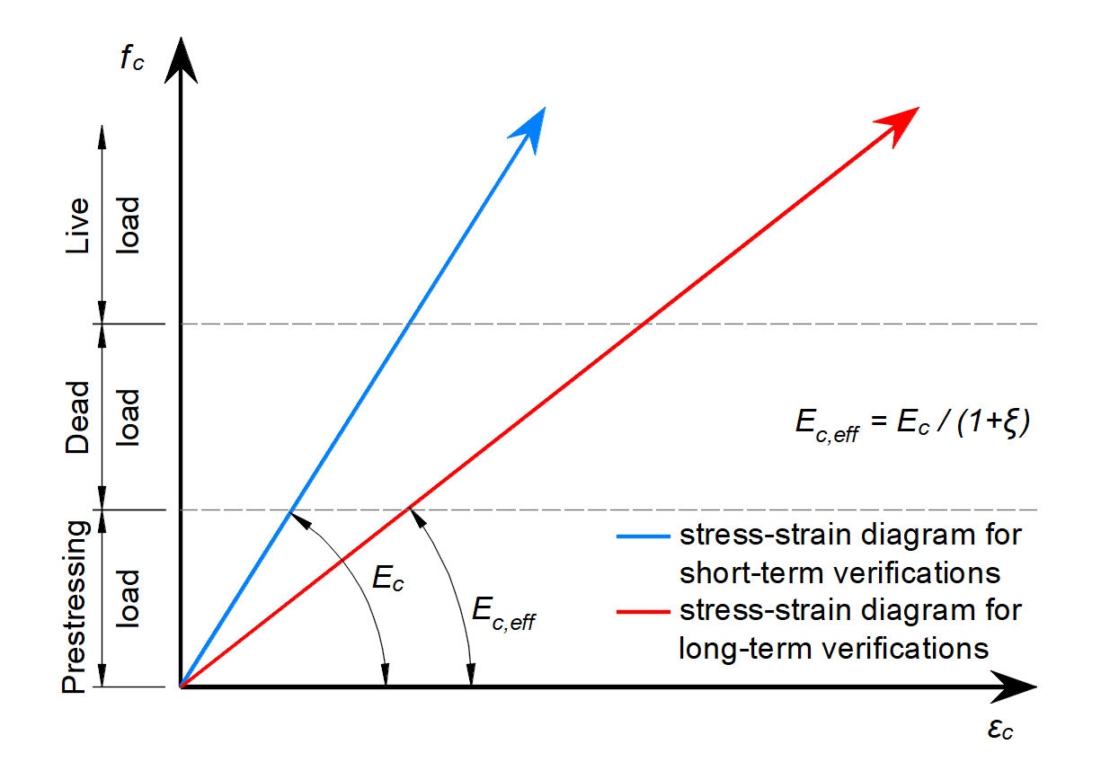
Serviceability combinations are divided into short-term and long-term types. Users can enable or disable deflection and crack width assessments for each. For long-term combinations, the sustained load duration in months must be specified. Short-term combinations exclude creep effects, while long-term combinations calculate the time-dependent factor ξ from ACI 318-19 Table 24.2.4.1.3 based on sustained load duration. The creep coefficient is taken from the concrete properties in the Materials tab. To account for long-term behavior, the modulus of elasticity Ec is adjusted using ξ, resulting in the effective modulus Ec,eff.
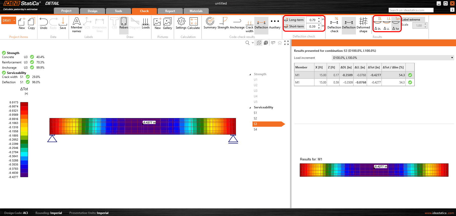
- Deflection check
Deflections are calculated for each combination selected in the Design tab. However, checks are performed only if enabled using the Long-term and Short-term buttons in the top ribbon, with limits set according to ACI 318-19 Section 24.2. Time-dependent deflections are assessed for long-term combinations based on these limits. Users can also view deflections separately for Dead Load and Live Load or see the total deflection (DL + LL). Load type selection is available in the Design tab for each load case.
- Crack width check
Crack width assessment follows the same rules as deflection checks. Time-dependent cracks are evaluated using long-term combinations, following the same selection process.
- Documentation
The chapter Structural Verifications According to ACI 318-19 has been added to the Theoretical Background.
Environment and Interface improvement
The UX and terminology in Detail have been adjusted for ACI users in both Imperial and Metric units, improving navigation for model, load, and reinforcement input. Results are clearer, and reports now include explanations with valid ACI references. Terminology has been adapted from Eurocode-based labels to ACI-specific naming for better clarity. More details below:
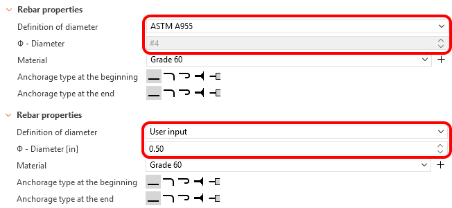
- Extended options for inputting reinforcement diameters
A double option for entering reinforcement diameter is now available for all reinforcement types, either by ASTM A955 standards or as user input based on the display unit settings.
- Combination renaming
The combinations are labelled as Strength and Serviceability, with Serviceability further divided into long-term and short-term. Users can choose whether to assess deflections and crack widths for each combination.
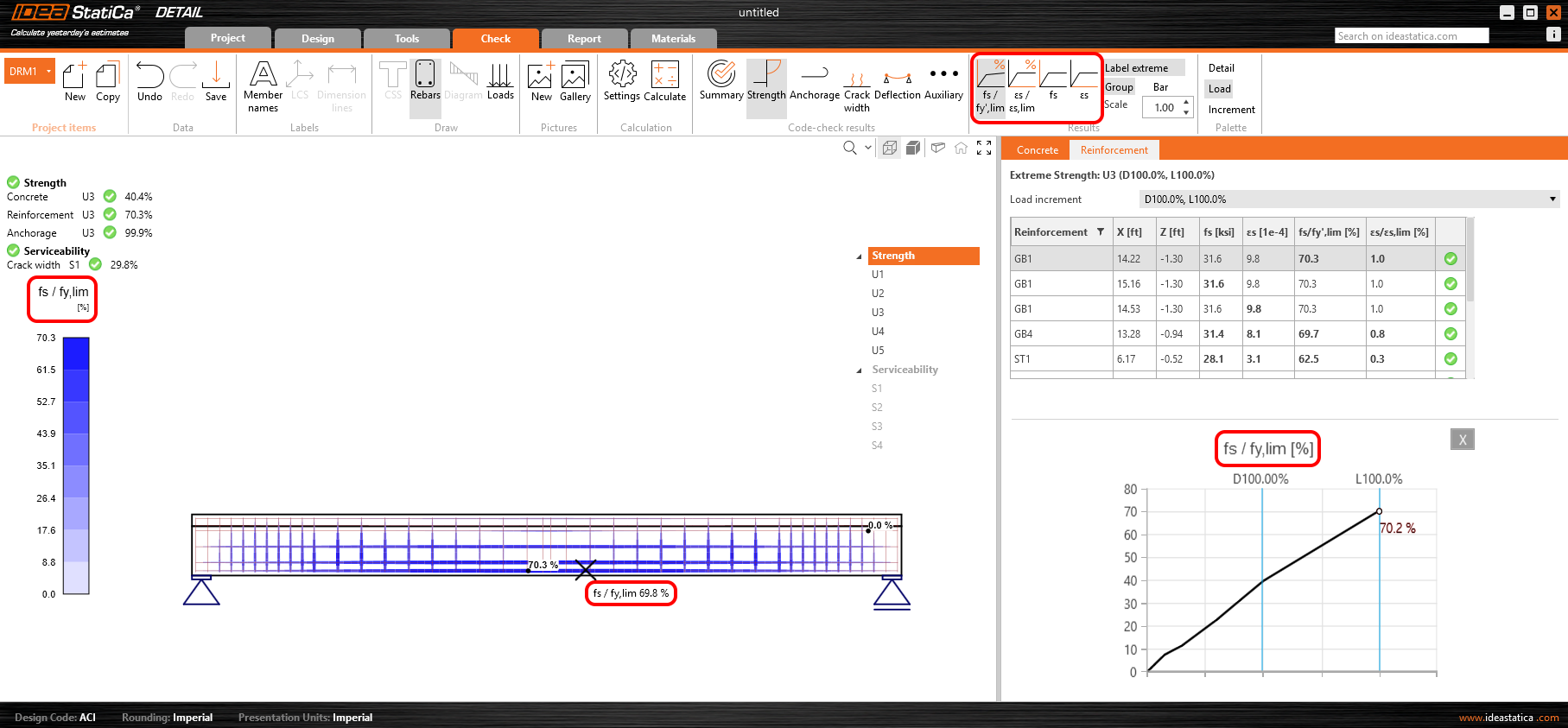
- Strength check nomenclature
The strength assessments have been named in terms of variable titles and descriptions to be consistent with the ACI standard.
- Deflection check nomenclature
For deflection assessments, the variables have been named according to the ACI standard and relevant tooltips have been added.
- Stress-strain diagrams in the Materials tab
On the Materials page, the graphs and the naming of the variables have been designed according to the ACI standard.
- Report adjustments
All of the mentioned modifications are reflected in the automatically generated report, where, as shown in the picture, you'll see the introduction of the time-dependent factor for sustained load and the specification of sustained load duration to account for creep in the structure.