
Slotted holes for the selected plate
Users can model real-world conditions more accurately by selecting which plate will include slotted holes, e.g., either in the fin plate or in the web of the connected member, as is typical in floor beam connections.
If the design requires it, slotted holes can also be applied to multiple plates. Previously, users couldn’t define the location of slotted holes, leading to incorrect bolt checks. With this improvement, bolt checks are now aligned with the actual design scenario.
Where can the slotted holes be used?
- The slotted holes can be set to any plate that is contained in the bolt assembly
- They can be set to one or more plates
- They can be defined for plates of the analyzed member
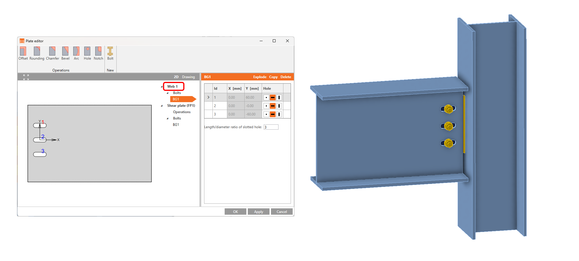
Defining slotted holes
The shape of the bolt holes can be changed in the Editor of the plate. You can open the Editor by selecting the plate in the 3D scene with the right mouse button. Another option is to use the Editor button in the operation header (the orange strip).

In the plate Editor of the plate containing the bolt, there is a list of all the plates that are connected by selected bolts. In the list, you can define, on which plate the holes will be changed to slotted.
Variant 1: Slotted holes for a fin plate

Variant 2: Slotted holes for a beam web
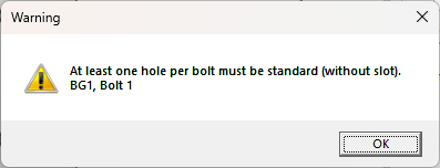
The slotted holes can be assigned to multiple bolted plates.
Nevertheless, be aware that there must always be at least one plate with standard holes so that the numerical conditions are followed.
From the general part of the Theoretical Background: Bolts in standard holes can transfer shear force in all directions, bolts in slotted holes have one direction excluded and can move in this selected direction freely.
To read more about the slotted holes in different standards, go to EN, AISC, CSA, AS, HKG, IS, GB, and SP Theoretical Backgrounds.
Custom sizes of the bolt assembly can be defined in the Material tab and saved to MPRL.