
Structural design and code-check of a steel frame (AISC)
New project
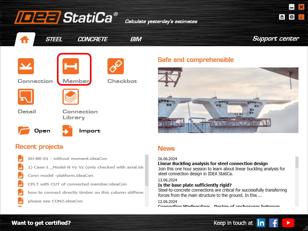
Start with launching IDEA StatiCa and select application Member (download the newest version).
Create a new project, enter its name and select a suitable folder where it will be saved. Then choose the design code/sub-code, starting material properties, and the type of topology (a frame).
From version 24.1 there is no need to create a special material with reduced properties - this is now taken care of by IDEA StatiCa Member at the appropriate time in the calculation process.
This approach can be applied to all relevant grades of steel - allowing the designer to check both existing and new structures.
Make the initial cross-section W10x60.
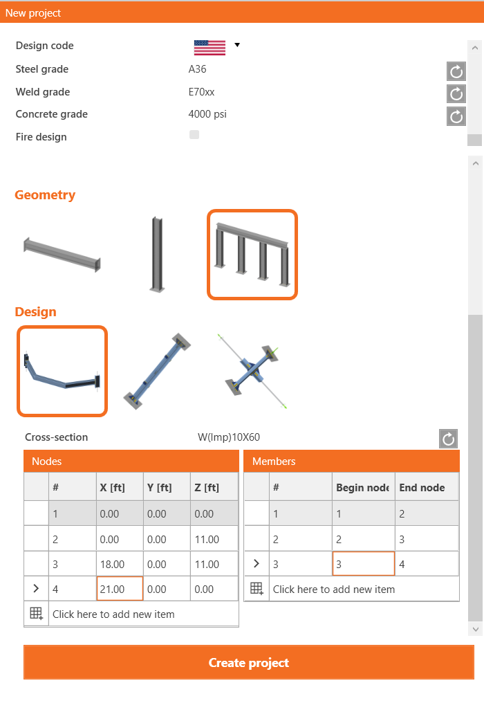
Add coordinates for the nodes of the structural frame and add the member connectivity using these nodes. Finally, click on Create Project ready to start modelling and amending the structural frame.
Amend the analyzed members, AM2 and AM3 to be W16x89 by adding a new member and selecting the correct section from the imperial I section database.
Related members
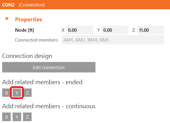
To add related members, which act as supports and load-transferring parts for the structural detail, click on the node cube in the 3D scene or select CON2 in the tree list. Here you can add either ended or continuous related members by clicking on the axis directions X, Y, Z according to the global coordinate system. Add 2 ended members in the Y direction.
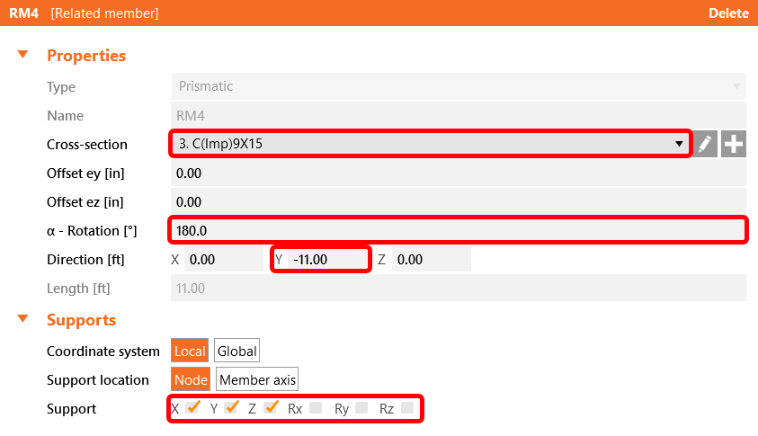
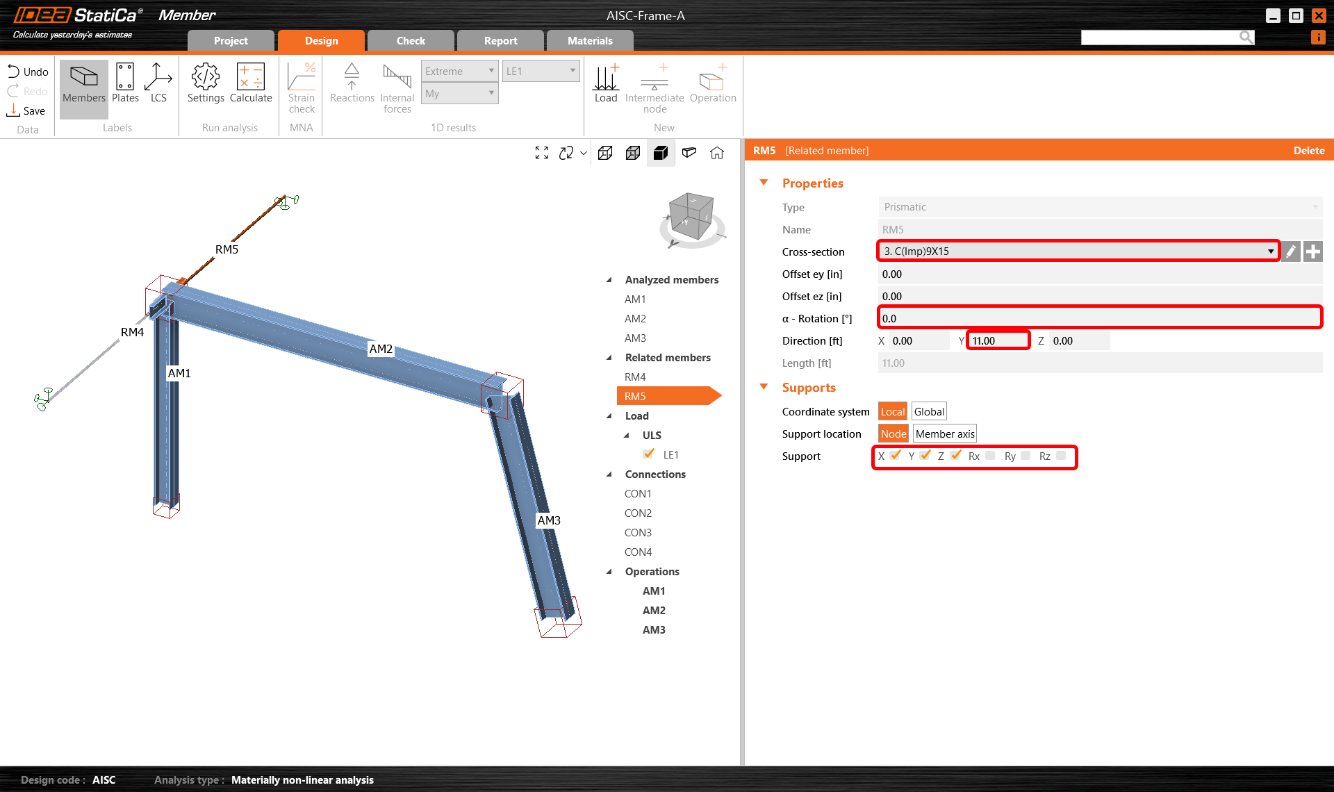
Then select the related member RM4 either in the 3D scene or in the tree list and modify its properties as cross-section, length, orientation, and supports at the free ends.
And modify the related member RM5 accordingly.
Loads
In menu Loads, you can add and modify load effects. A load effect stands for a group to which you can add one or more distributed loads on any analyzed or related member. Alternatively, within a load effect, you can input nodal internal forces on member ends.
One load effect containing a set of line loads has been generated automatically for all members. Delete 2 of them by clicking the left mouse button on each row in the tab and selecting Delete or clicking on the icon in the ribbon.
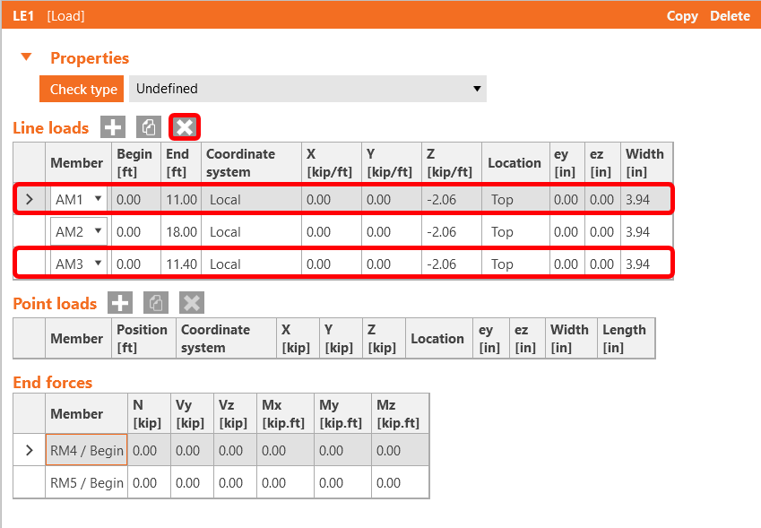
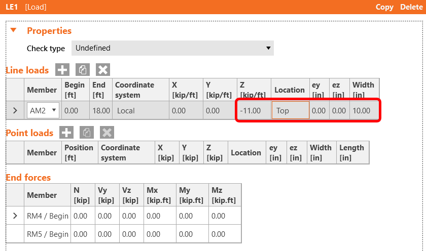
Then assign one distributed load to member AM2 and modify its magnitude to -11 kip/ft and width to 10" to match the beam.
Connections
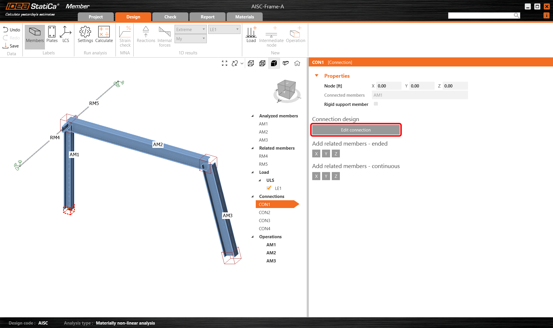
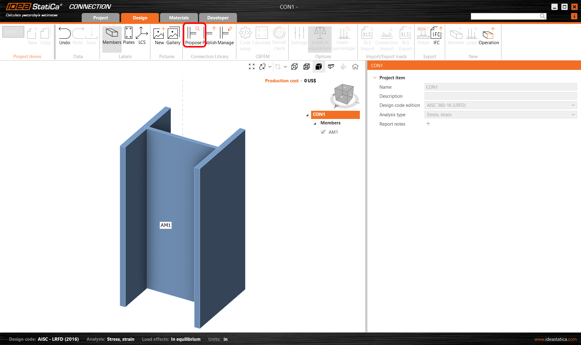
Next, you can design the joints. Select a node cube in the 3D scene or select a CON# in the tree list and click on Edit connection.
Start with joint CON1 at the left column base. IDEA StatiCa Connection application module opens, and you can design the joint by adding the manufacturing operations.
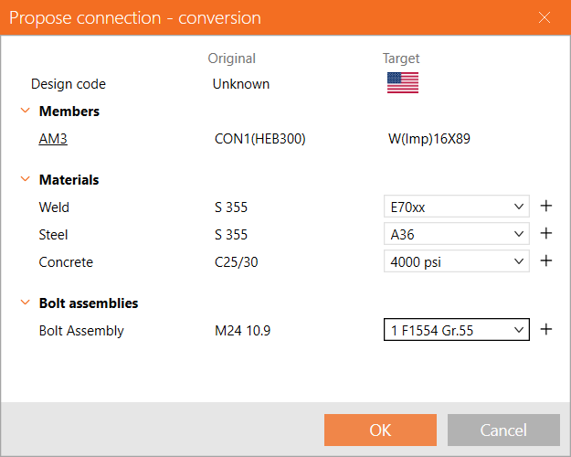
In this case, add just one Base plate operation and modify its parameters. Click on the Propose button in the ribbon.
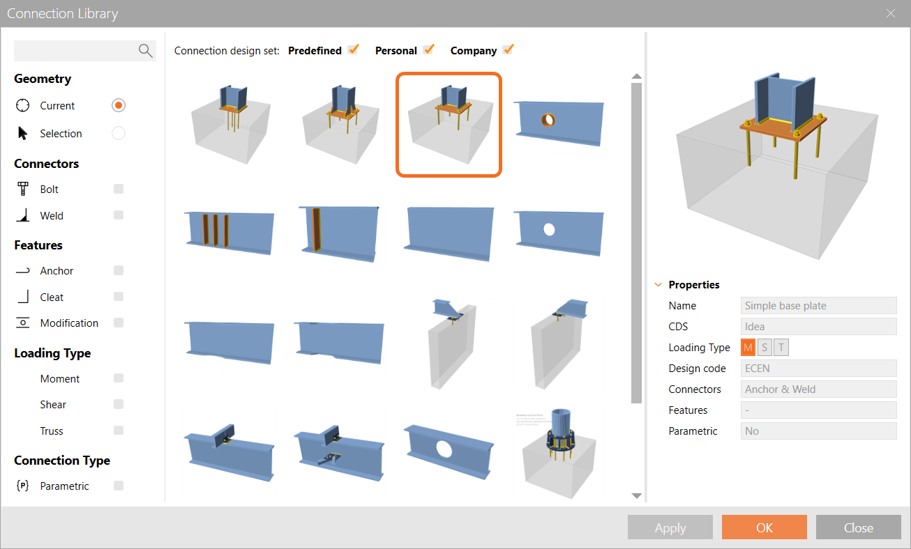
Afterward, select a Simple Base Plate and confirm your choice by clicking OK. You may notice that the Design Code is different but in the next steps this is taken care of.
Select weld type E70xx, steel type A36 and concrete type 4000psi.
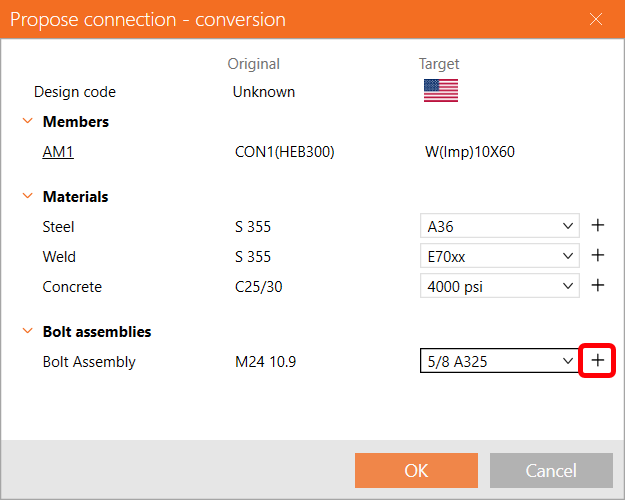
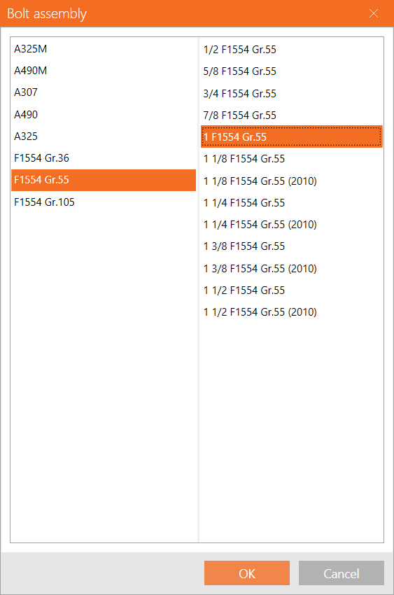
Press the + symbol next to bolt assembly type, choose 1" F1554 Gr. 55 and then press OK to continue.
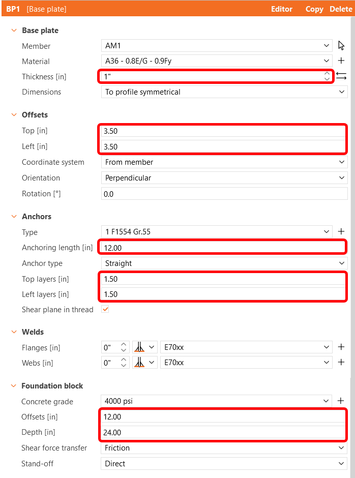
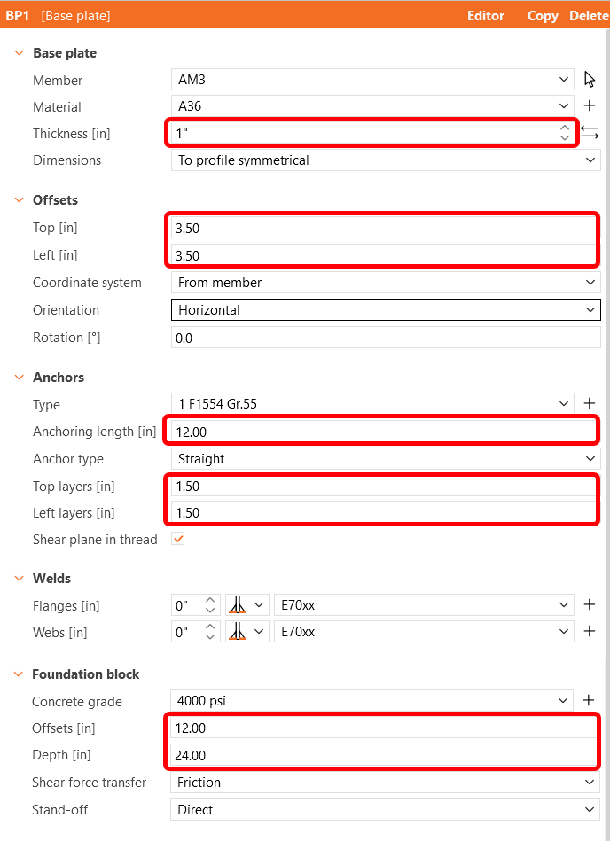
After that, configure the parameters in BP1 according to the picture below, save the connection settings, and finally close the connection application. Notice how the connection you have defined appears in the Member model.
Next, choose the joint CON2 and click on 'Edit Connection' within the IDEA StatiCa Connection module.
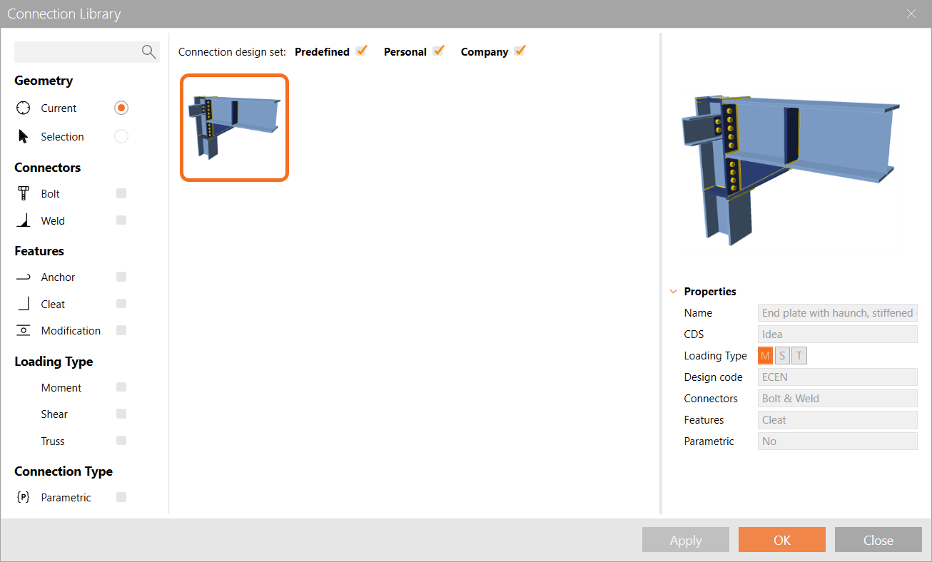
Again propose a connection from the Connection Library. This is a great way to create connections which are based upon already created templates. The suggested connection might not be an exact match but as we have already seen it is very easy to modify something to make it fit.
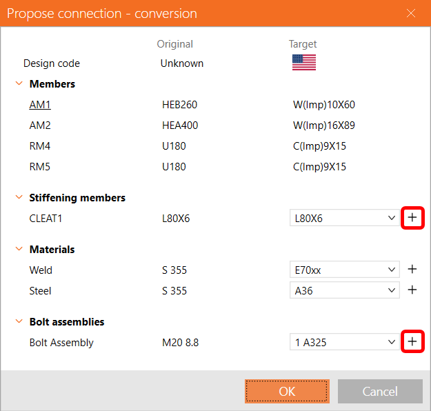
The main members are automatically picked up from the model. All that is required is to map the additional features to ones that are correct. Change the angle size to 3 1/2 x 3 1/2 x 1/4 by navigating to the relevant L library via the + button, the steel type to A36 and the weld type to E70xx. Finally change the bolt assembly to 3/4 A325 before pressing OK.
The section libraries in IDEA StatiCa are quite comprehensive covering several editions of the AISC standards.
Consequently, your connection would look like in the following picture.
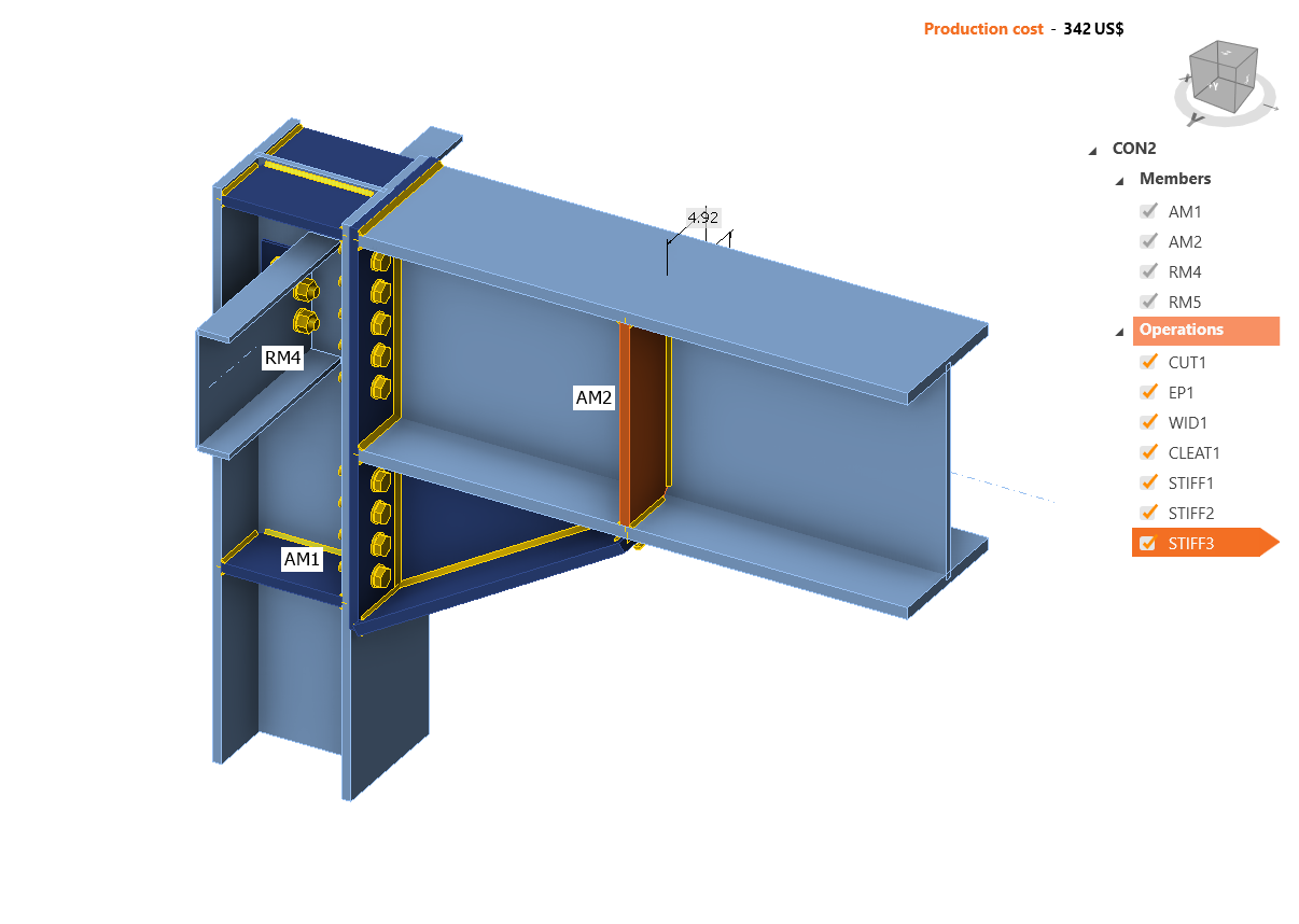
Save this connection before closing.
Continue by editing the joint CON3.
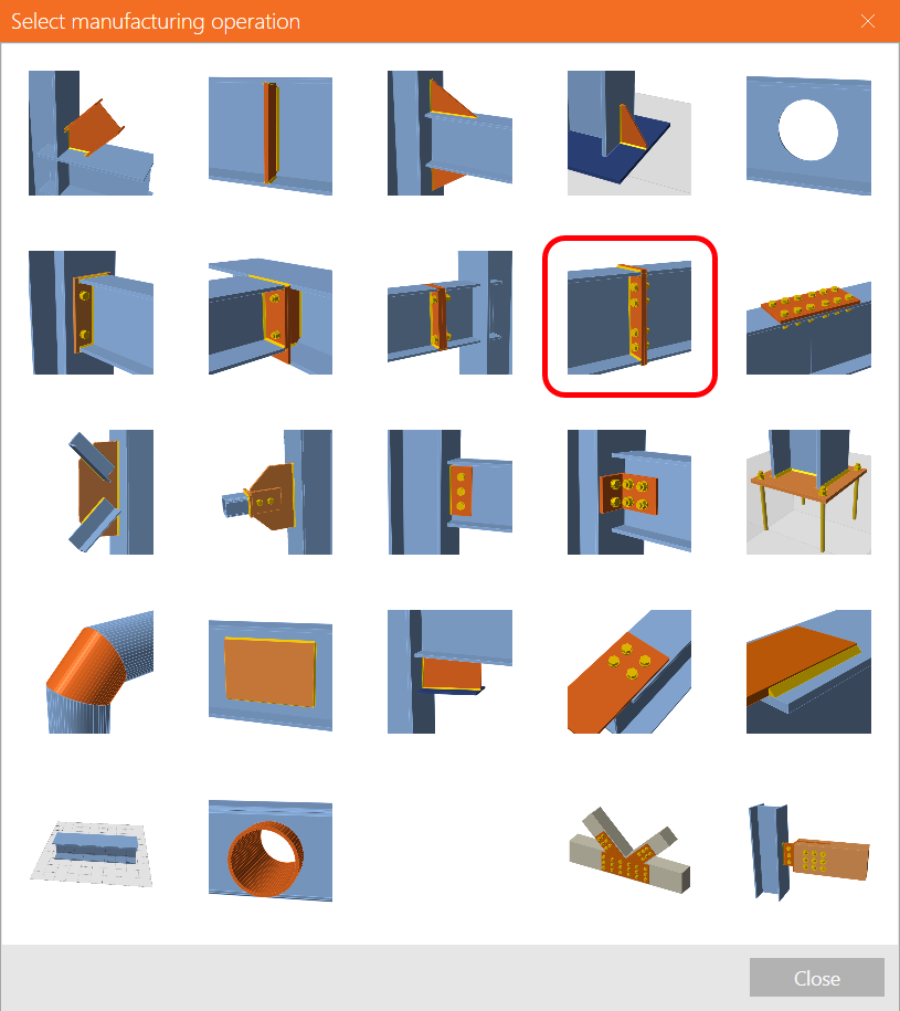
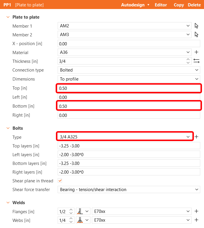
Here we are going to add a plate to plate operation to create a member splice.
Adjust the parameters as follows to finalize the connection.
Save and close CON3.
At last, edit the joint CON4. Even though the software offers us to simply replicate the same design as for CON1, we will edit the connection to create a different one.
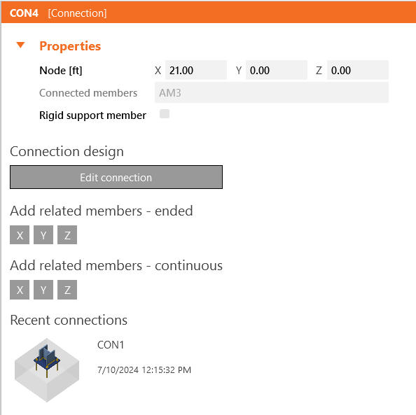
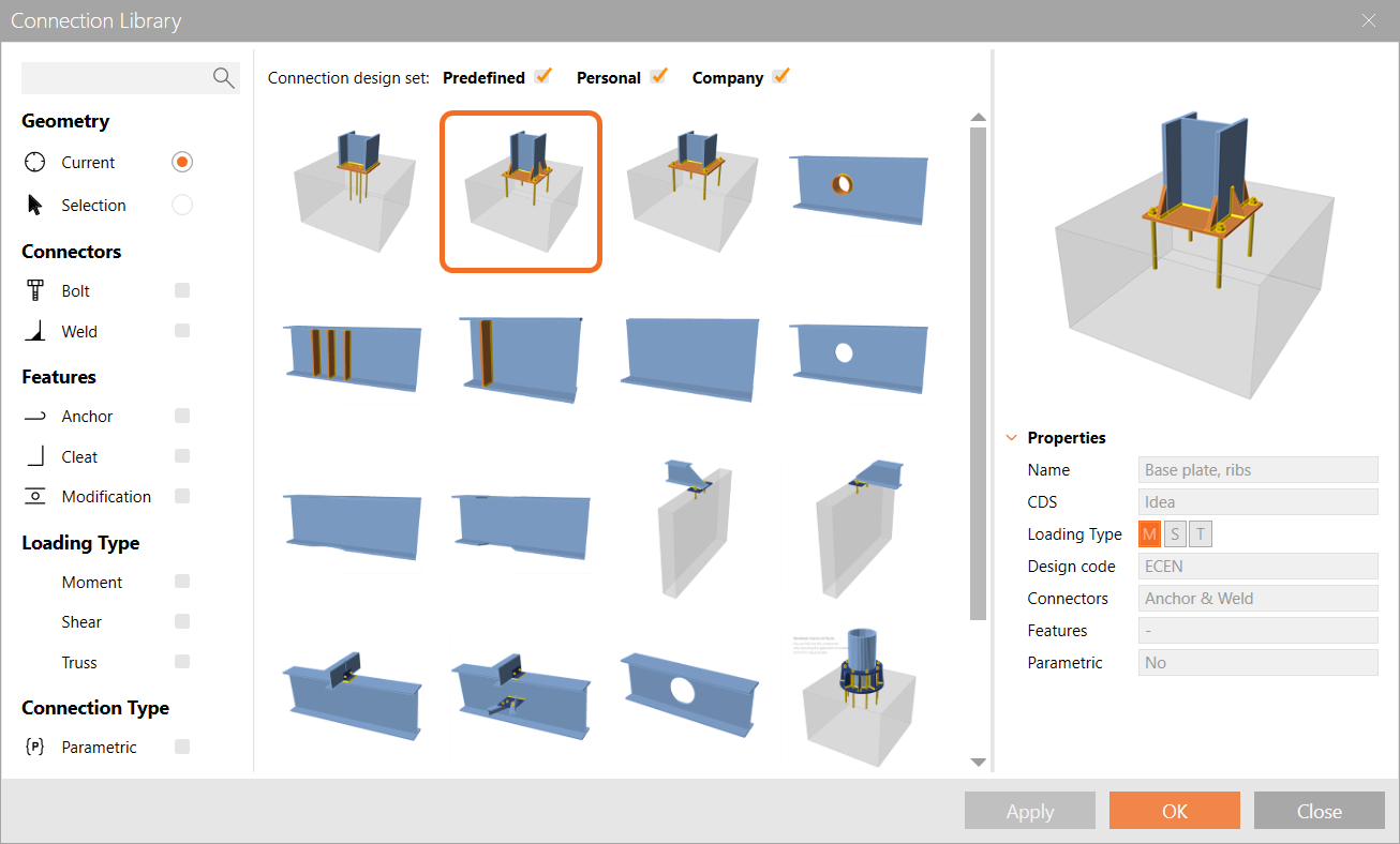
Open CON4, click on Propose and select the design of a base plate anchoring with stiffeners as shown in the following image.
Select weld type E70xx, steel A36, concrete 4000psi and bolt assembly 1" F1554 Gr 55.
To finish the design by modify the BP1 operation as shown in the picture below.
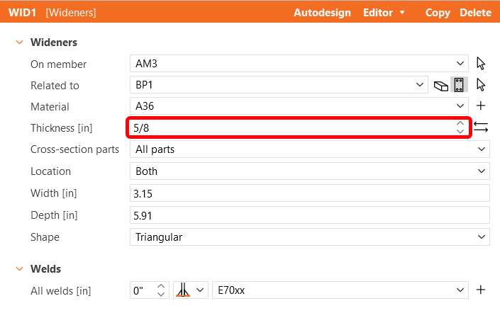
Also check the thickness of the stiffeners in WID1 as per the image below.
Check
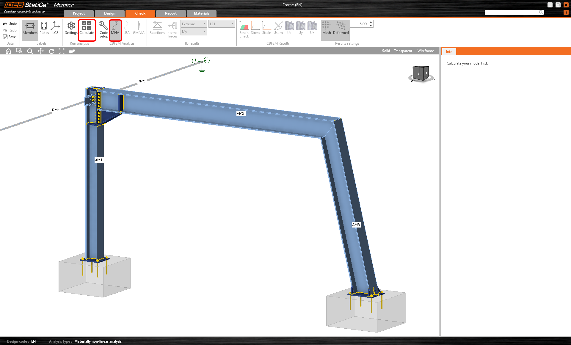
Let's proceed to the Check tab and perform the analysis. Analysis in IDEA StatiCa Member is calculated in three steps using the CBFEM technology. First, analyze the MNA (materially non-linear analysis) to check the structural capacity, then calculate the LBA (linear buckling analysis) to investigate the structural stability and finally input the initial imperfections to appropriate buckling shapes and calculate the GMNIA (geometrically and materially non-linear analysis).
Firstly, for this particular complex project, you need to raise the Number of analysis iterations to 40 and the Divergent iterations count to 15 in the Code setup (on the Check tab) to provide enough computational capacity for the calculation.
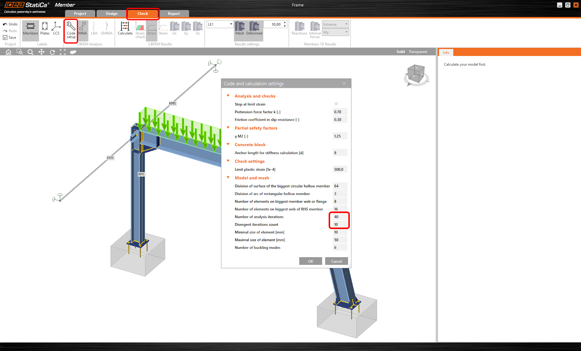
And then select the MNA analysis and press Calculate.
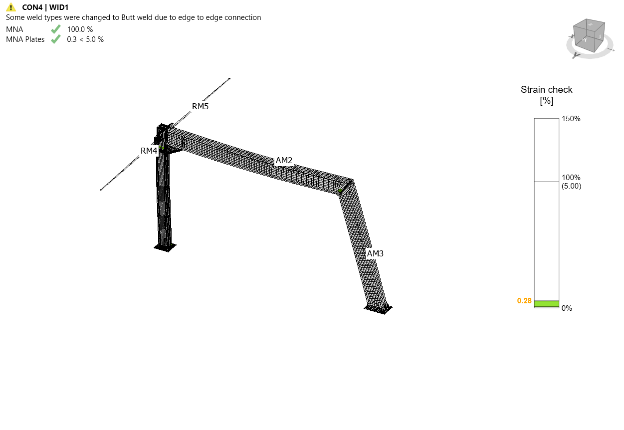
The MNA analysis results are displayed, and you can check the status of each structural part as well as results in the 3D window, e.g. the strain distribution in the analyzed part of the structure.
Next, switch to the LBA analysis and repeat the Calculation.
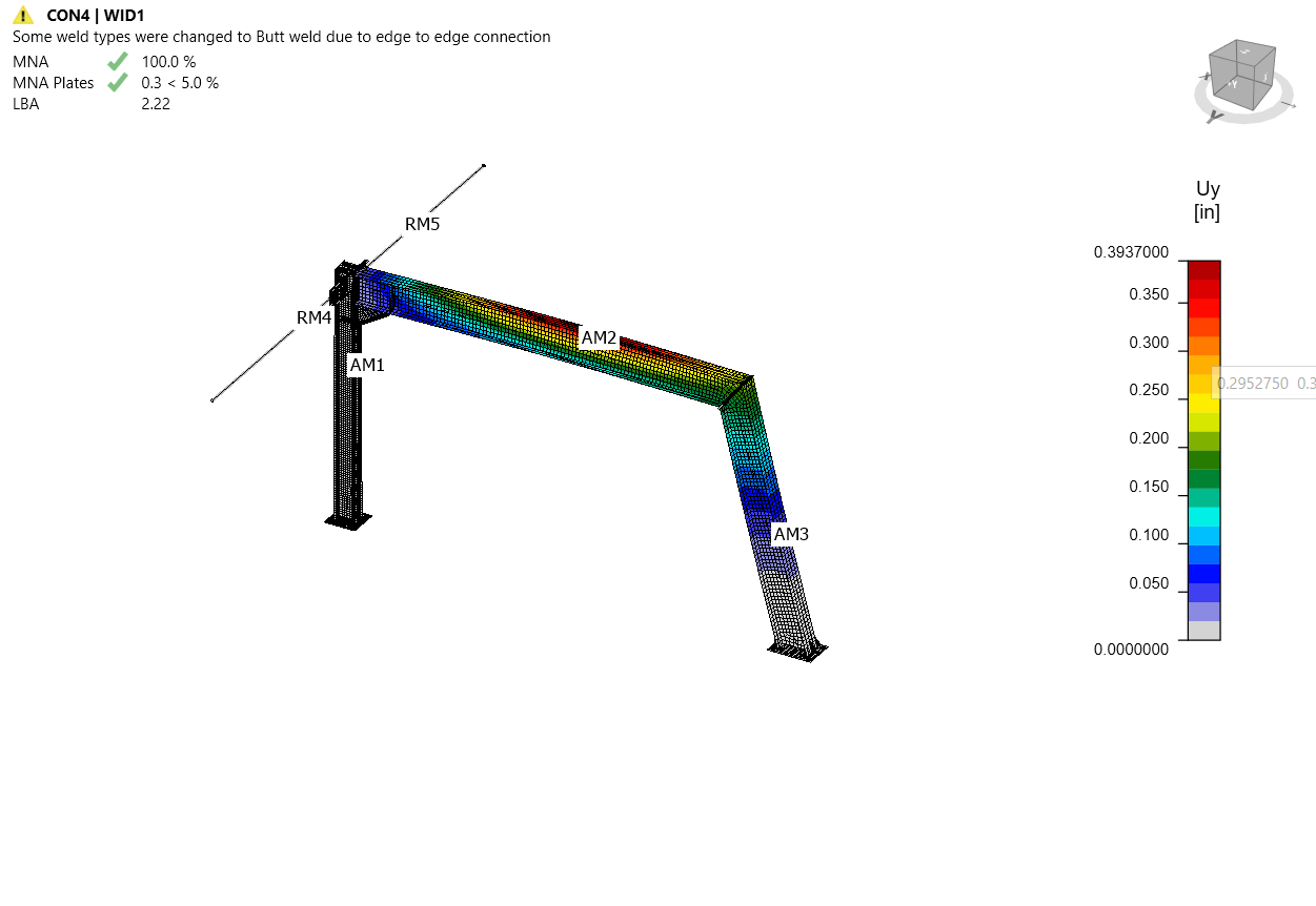
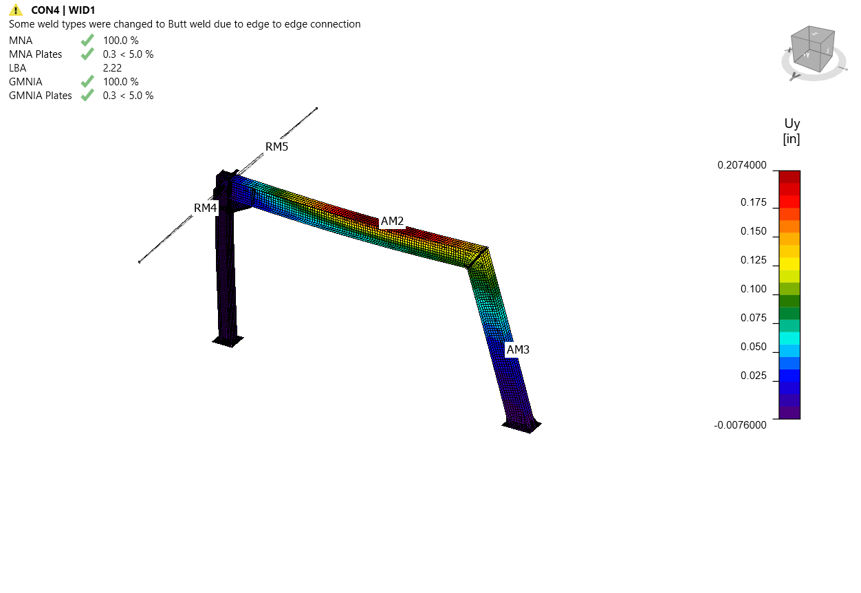
You can read the buckling shape factors in the tab and see the first buckling shape 1 visualized while turning on the Uy display to better overview of deformation.
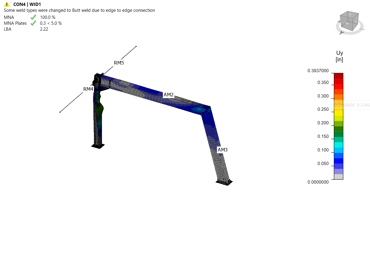
You can browse the visualization of the other buckling shapes by selecting them in the tab, e.g. buckling shape 6.
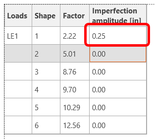
Since at least one of the buckling shape factors is less than 15, switch to GMNIA to perform the non-linear analysis of structural stability. Choose the most critical buckling shape or a combination of buckling shapes and input the initial imperfection of the critical beam. In this case, choose the first buckling shape 1 as the most critical one. Switch to the GMNIA tab in the right panel and determine the imperfection of 1/4" (L/1000 = 18*12/1000 = 0.21", say 1/4"), which you type in as the Amplitude in column 1.
Then again, click the Calculate button. In this case, the analysis may take several minutes.
For arguments sake let us assume that the analysis does not complete, you can notice that the GMNIA applied loads have not reached 100%, which means under given loads, the structure loses stability OR you just want a higher minimum buckling factor - you need to strengthen the frame.
Operations
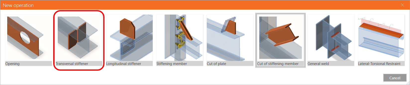
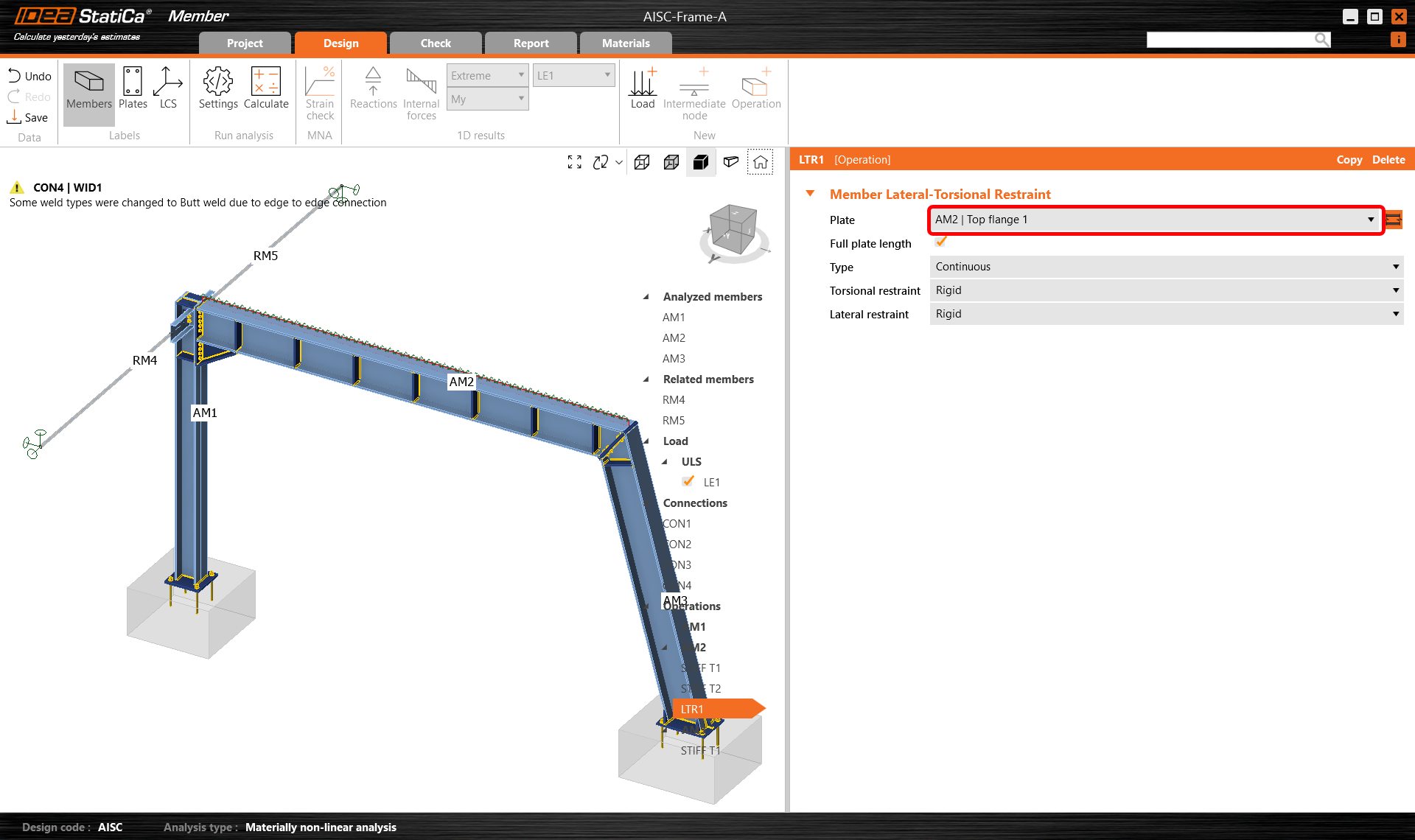
Go back to tab Design and in the tree menu, navigate to Operations, right-click on AM2, and add Transversal stiffeners to strengthen the most stressed frame corner and decrease the buckling effects.
Modify the stiffener parameters to introduce a series of regularly spaced stiffeners along the member.
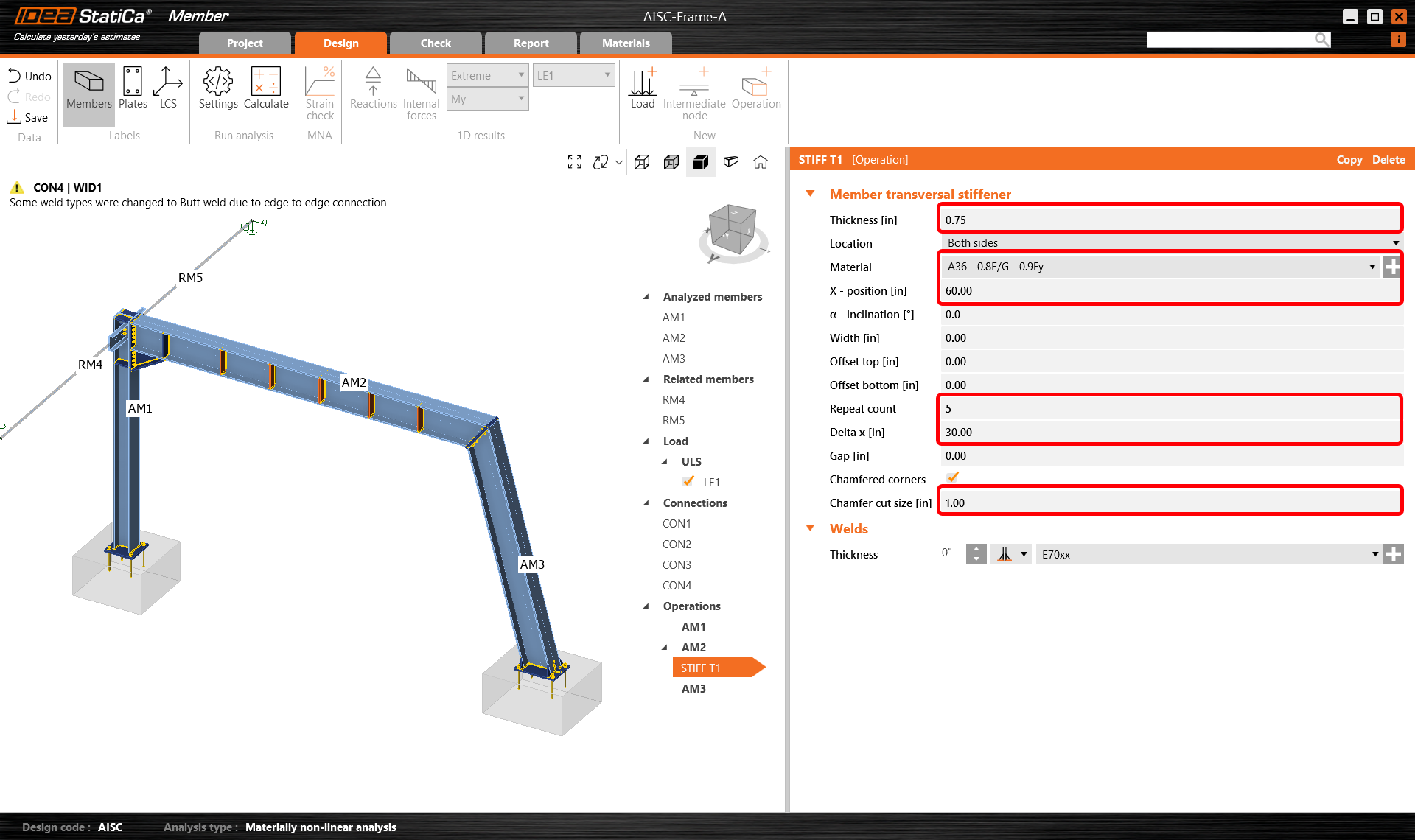
Then modify the stiffener parameters and add one more transversal stiffener to the same beam AM2 and another one to the column AM3 and set them in the right position.
Copy the STIFF T1 operation and set the distance of a single stiffener (change the count to 1) to 220".
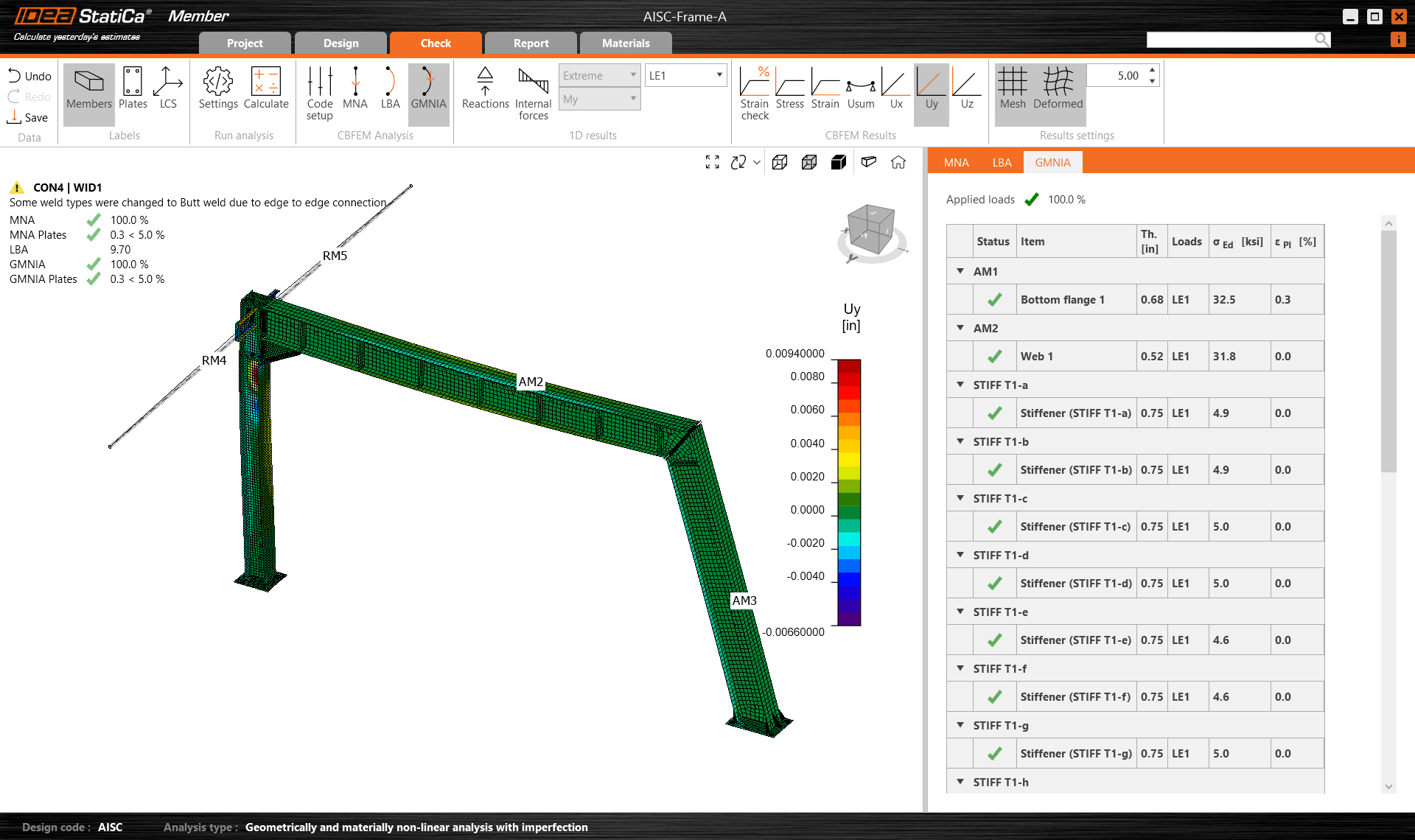
For AM2 we can also make allowances for the stiffening effects of the roof deck by introducing a lateral torsional restraint operation:
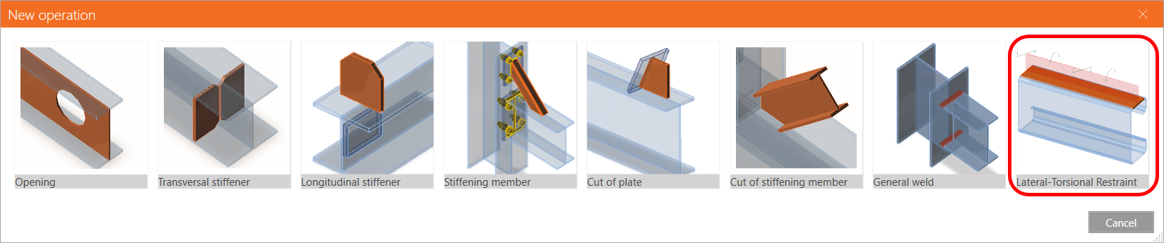
Modify the parameters to take into account the actual positioning of (say) the purlins or as in this case a continuous deck.
Moving onto AM3, create a new stiffening operation and set the properties as shown in the following picture.
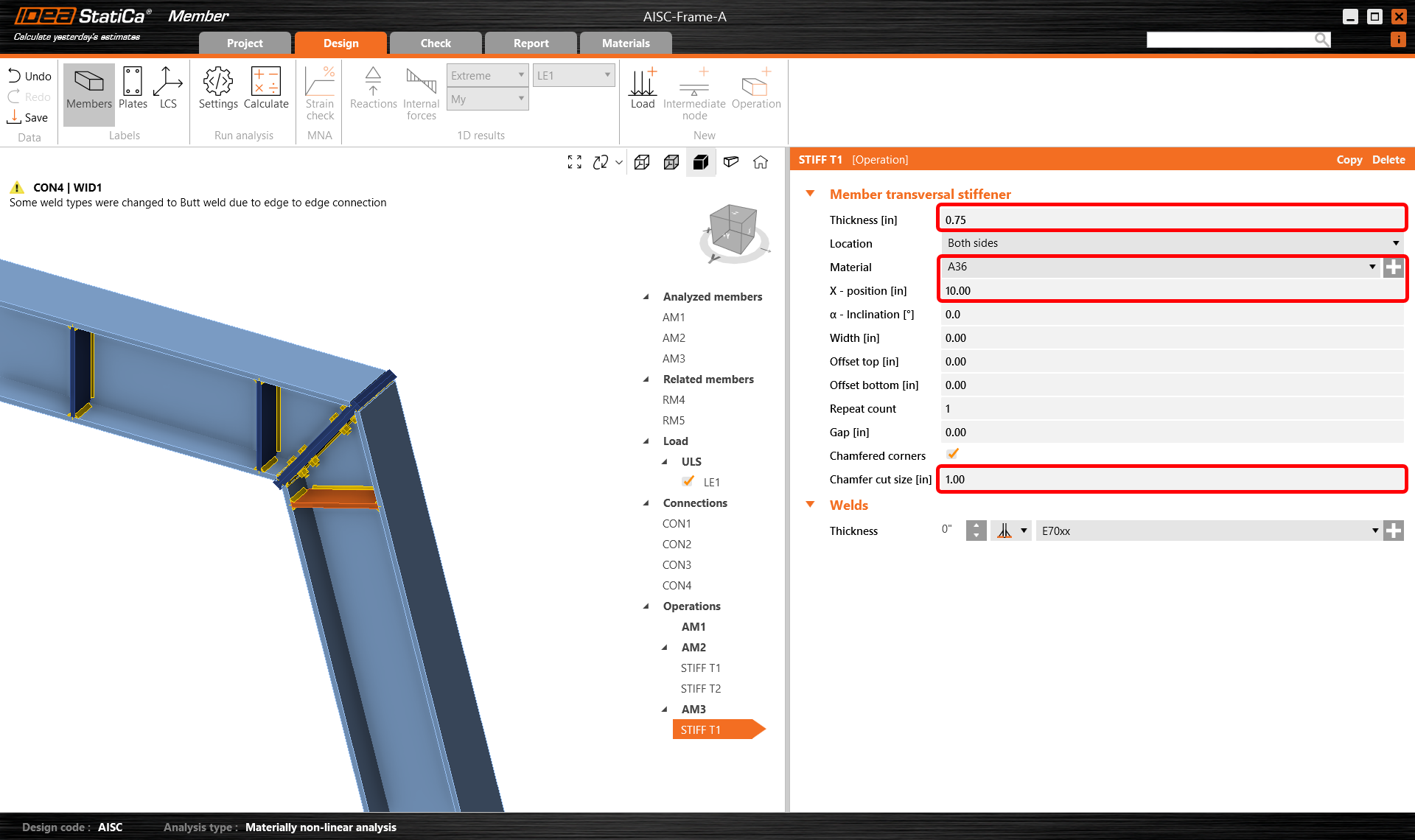
Now go back to tab Check and repeat the calculation in three steps - MNA, LBA, GMNIA. The designed frame passed the stability code-checks with applied initial imperfections, and you can browse the results such as strain distribution and internal forces diagram.
As you can see by examining the new results, the strengthening and additional restraint has a big impact on the buckling factor allowing the design to be stronger without the need for increasing the section size. In such a situation, IDEA StatiCa Member is a great application for conducting advanced studies quickly and efficiently.
Report
At last, go to the tab Report. IDEA StatiCa offers a fully customizable report to print out or save in an editable format.
Congratulations, you have designed, optimized, and code-checked a steel frame according to AISC.
Chcete zlepšit své dovednosti? Navštivte náš Campus
RELATED CONTENT
Nosník (EN)
Přiložené soubory ke stažení
- AISC-Frame-A.zip (ZIP, 7,3 MB)