Midas Civil BIM link for bridge load rating
We will show the procedure on a simple model of a prestressed single-girder bridge with three spans. We have prepared a download in the form of a zip file that contains all the files you need to complete this tutorial. It is available here. Please download this file and unzip it to a location of your choice.
1 Import
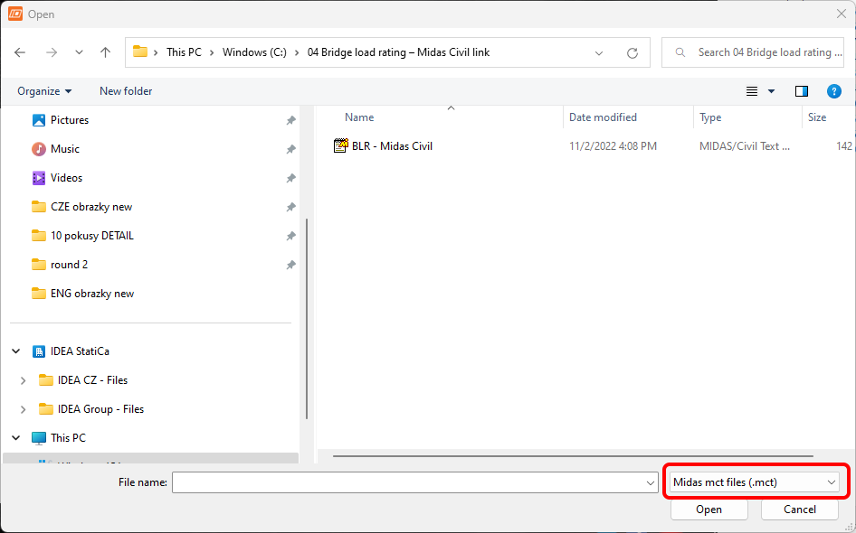
Start the IDEA StatiCa application, select Import from other programs on the BIM tab, and select the prepared .mct file. A source model in Midas Civil is also available in the downloads.
If you are importing for the first time, set up the generation of design groups and design members. The program automatically joins the imported bridge superstructure into one design member. This setting can be saved and will not be displayed next time.
If the program discovers any issues during the import, they will be displayed in the Import Details window. In our case, it is a material with zero density used for the self-weight calculations of the crossbeams.
The imported model should look like this in the 3D scene.
After import, you have to set the calculation parameters in the Project Data tab. The first of them is Code and National annex, then the Type of bridge and finally, turn on the Bridge load rating functionality.
The program will give you a warning message, suggesting it would be helpful to check the group settings after making this change. For the correct import of internal forces from the Midas Civil software, it is necessary to correctly distinguish permanent load cases, traffic loads, and other variable loads in Midas Civil.
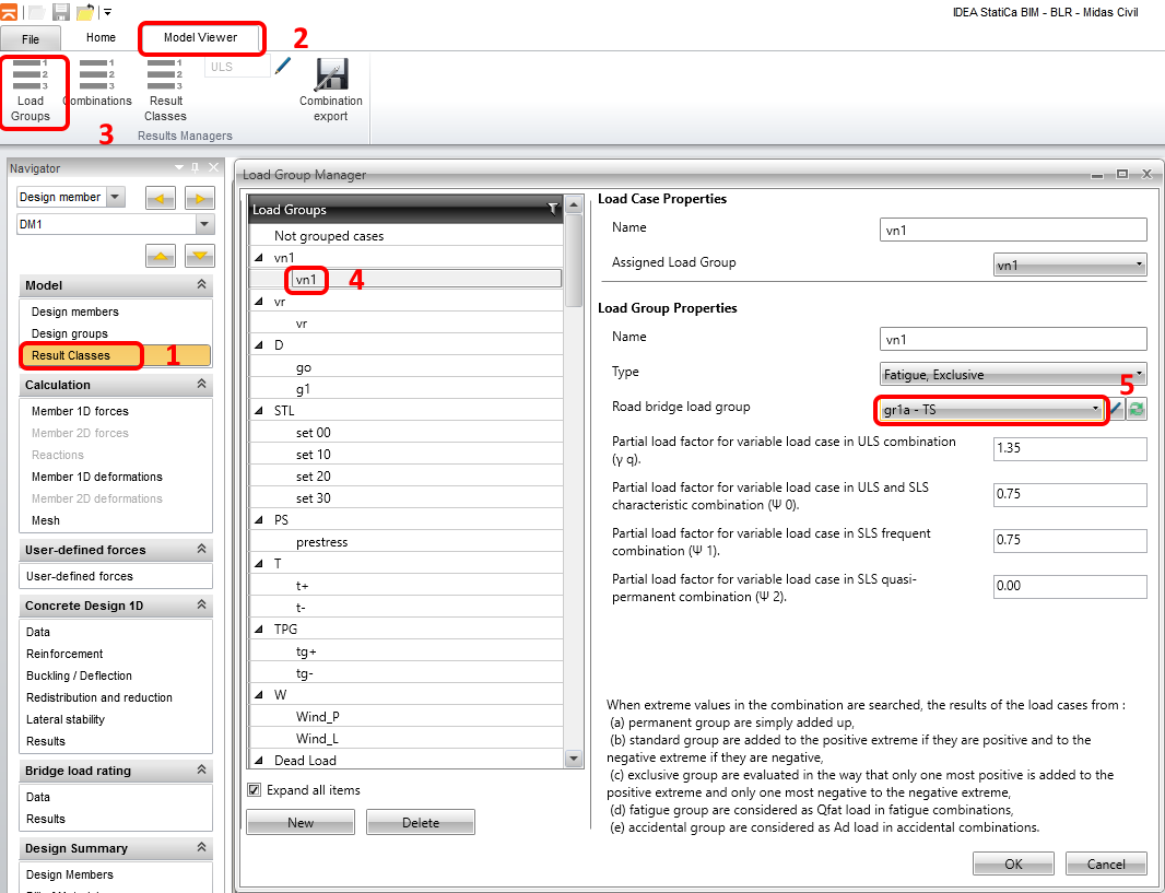
In the next step, check and set load groups of load cases. Start with the load group vn1, which is a code-based vehicular load to determine the normal load-carrying capacity of the bridge. It is important to distinguish this load condition as a traffic load, because by iterative searching for multiple defined traffic load cases, the program calculates load-carrying capacity.
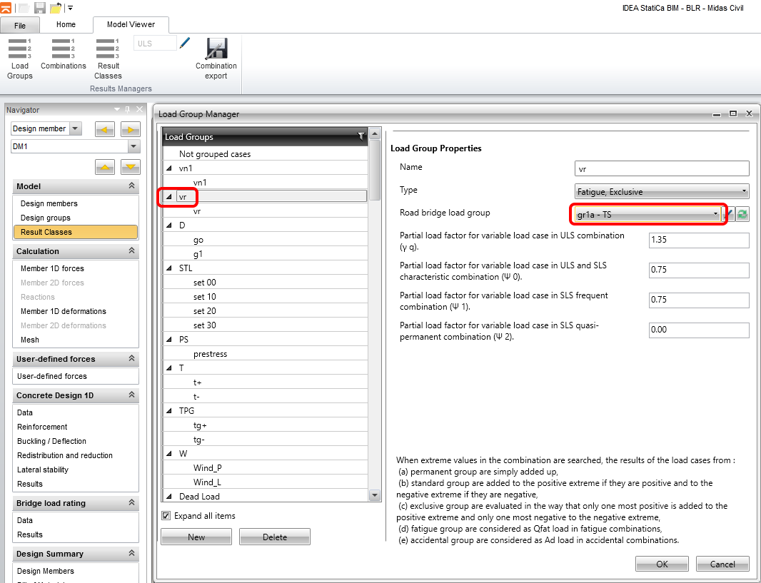
Similarly, continue with the load group vr, which is the standard six-axle vehicle to determine the reserved load-carrying capacity.
Next, continue checking the settings for the g0 (dead load) and g1 (a dead load of attachments), and prestress loads.
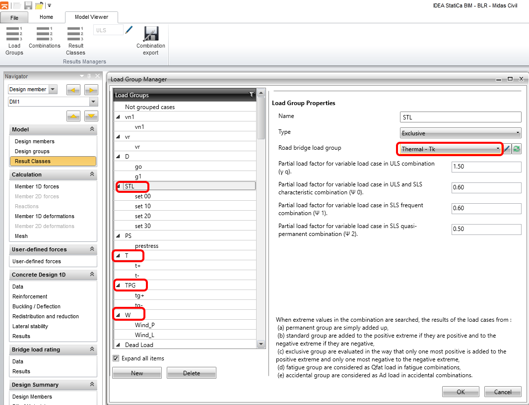
For the settlement, temperature and wind load groups set the load group type Thermal - Tk. This is a way how you distinguish them from traffic loads and permanent loads. The program ignores the values of load factors and combination factors for individual load cases because they were taken from the load combination settings in the Midas Civil program.
In the next step, check whether the internal forces have been imported correctly by comparing the envelope of bending moments from the combination ULS _6.10_vn1. You can set Scale 15.5 for better visualization.
2 Reinforcement definition
The next step is the definition of the reinforcement and the setting of sections for the check. First, divide the superstructure into five reinforcement zones as shown in the figure, and start defining the length from the last zone.
For the whole structure, we will have 2 types of reinforcement, for negative and positive bending moment. You can add or edit reinforcement by buttons as shown in the following picture. A-A type for positive and B-B for negative bending moment zones. Check position we will set later.
We will use prepared reinforcement templates for both types. Open the reinforcement editor run Reinforcement input dialog and find re A-A.nav file in the project folder.
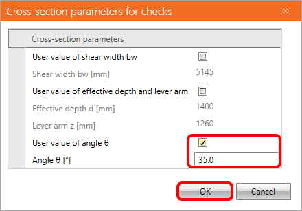
In the user settings tab, enter the user value of the diagonals angle to 35°, and click OK. Close the reinforcement editor to complete the A-A types setting. Similarly, use the reinforcement template for type B-B.
3 Load rating calculation setting
To set the load rating calculation, switch to the Data tab in the Bridge load rating section. The Check Settings tab defines the checks to be performed, we will return to this settings later.
The estimate load rating factor can be set if you want to speed up the calculation and, last but not least, the load rating type which will be calculated is set. In our case, normal and reserved traffic load cases are defined in the source MIDAS model. So you will set only Normal and Reserved for calculation.
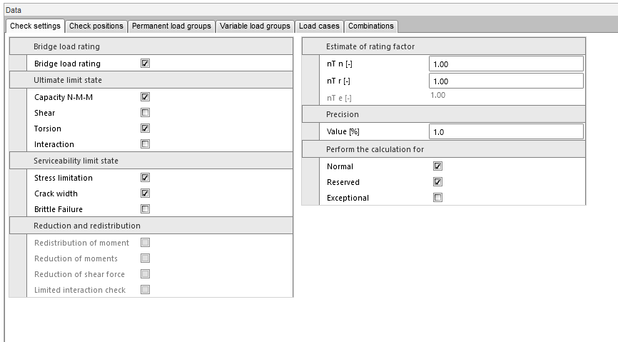
At first, we will perform the load rating analysis in Sec 1- support 2. We will consider checks for bending and torsion.
Subsequently, the analysis is carried out at a distance of 1.5 m from the support, including consideration of shear and M-V-T (moment-shear-torsion) interaction.
On the second tab, set Check positions for individual sections checks.
On the Load case tab, set the dynamic coefficients and weight of one vehicle corresponding to the weight of the vehicle in the 3D FEM model in the Midas program for the traffic variable effects.
The Combinations tab is used to generate and set combinations for individual load rating types (normal, reserved, and exceptional).
After pressing the Generate button, combinations will be automatically generated. We will revise and reduce their number in the next step because some of them are superfluous. For example, in the first line, there is a combination LR_6.10_vr Normal, in which vr (reserved) traffic load is used for the calculation of normal load capacity. This combination does not make sense, so delete it along with the other redundant combinations.
The final load combinations list should look like this:
4 Load rating calculation
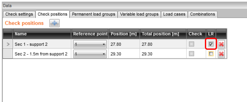
Switch again to the Check position tab and switch the LR checkbox for Section 1. This defines, that the load capacity calculation will be performed only for section 1 (which is the support).
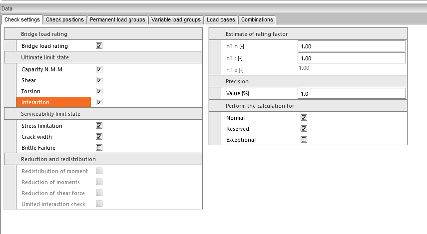
Then return to the Check settings tab and make the settings.
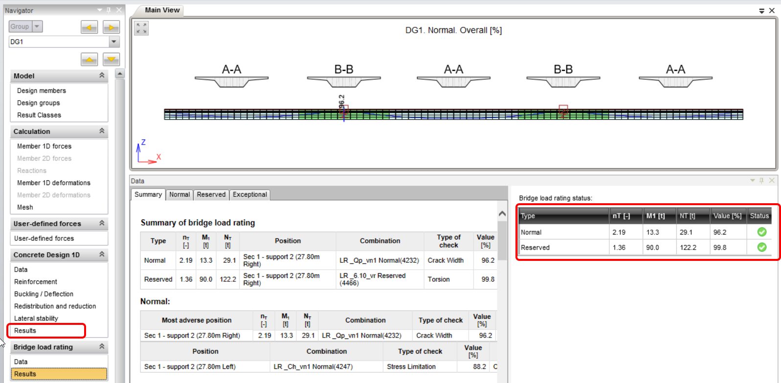
Switch to the Results tab. This will automatically start the calculation, when the program iteratively searches for a multiple of the specified traffic load, at which one of the checks will have a 100% value. After completing the iteration, you can view the resulting load capacity values and load multiples in the right part of the screen. On the left side of this field, the critical check that decided on the load capacity is highlighted.
Now perform the check of section 2 including consideration of the M-V-T (moment-shear-torsion) interaction. Switch to the Check positions tab and switch the LR checkbox for section 2.
Then switch to Check settings tab and update the settings.
Switch to the Results tab to start the calculation again.
By clicking the Detailed button in the upper ribbon you will switch to the RCS program, where you can view the detailed checks of individual limit states.
5 Report
In the last step, go to the Report tab, field Detailed. IDEA StatiCa offers a fully editable report that you can print or export to various formats, including pdf.


