
Parametric design in IDEA StatiCa Connection - Advanced (02)
Imagine that you want to use a template from the Connection Library for your connection, but you need to ensure that all operations used meet the standard requirements, specifications, and regulations used by your company for the particular contract.
- The first option is to review the operations individually and check the relevant fields.
- The other one is to create your parametric template, where all necessary checks are included.
Let's reuse the joint that has been utilized for the parametric design in IDEA StatiCa Connection - Basics (01).
The goal of the design is to achieve a fully parametric symmetrical splice connection and have control over the following data:
- Thickness of the splices
- Number of rows of bolts
- Distance between the bolts in both directions
- Backing plate usage
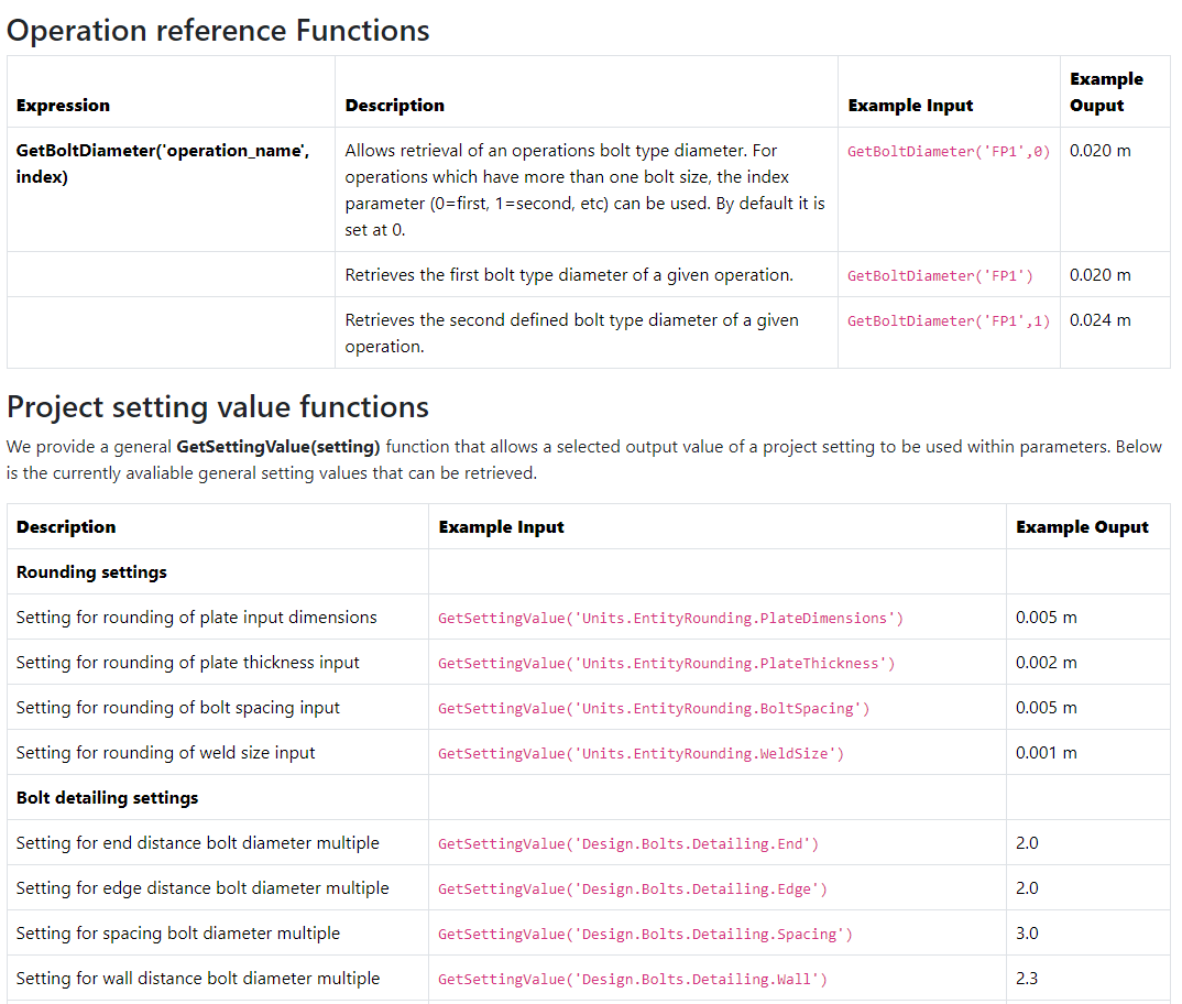
The link to our web page provides access to all possible expressions and operations used in this tutorial. If you are familiar with Excel, you will find many common operations.
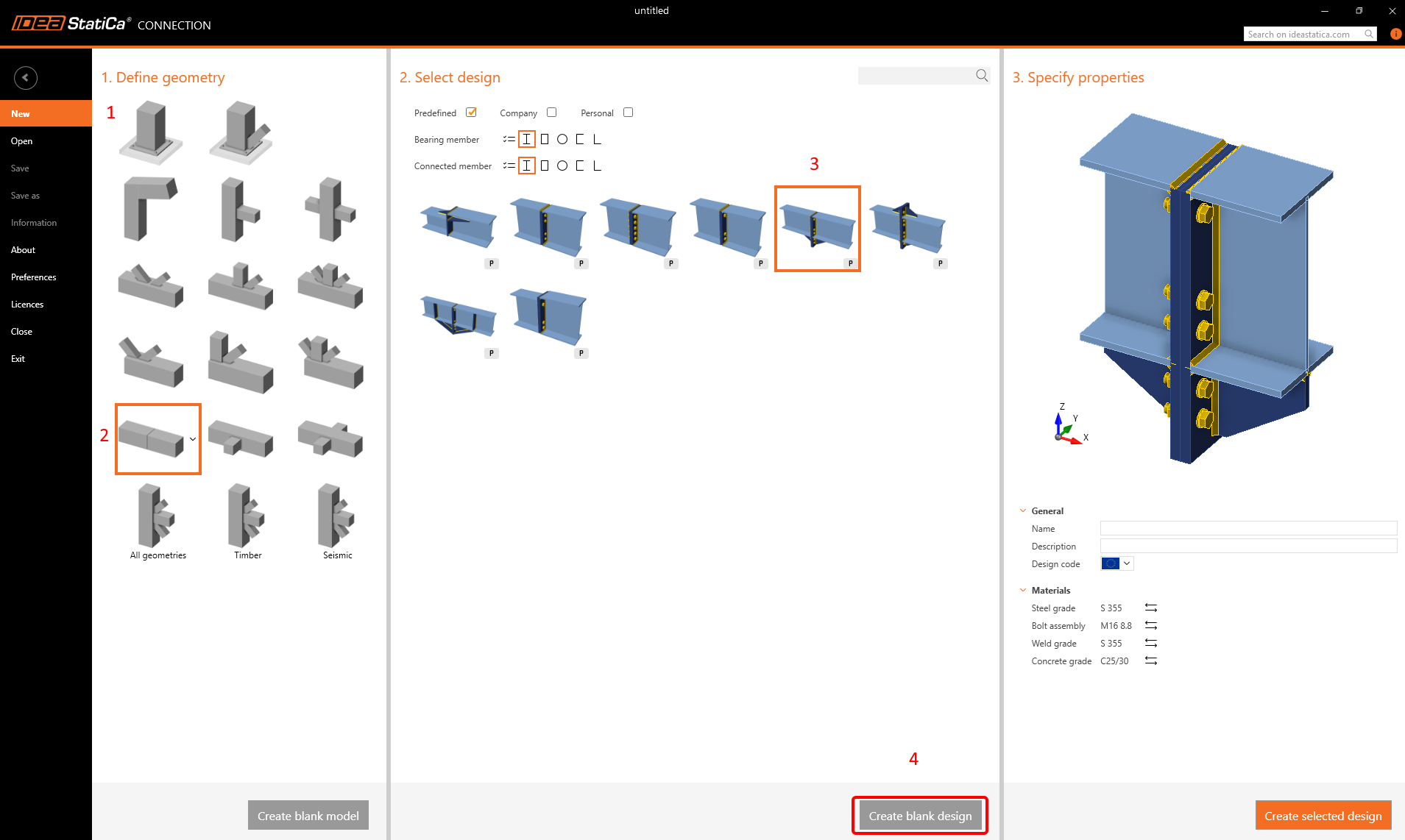
1 Design a connection
Use the following template to create a fundamental connection for your tutorial (the same as in Basics (01).
Thickness of the splices
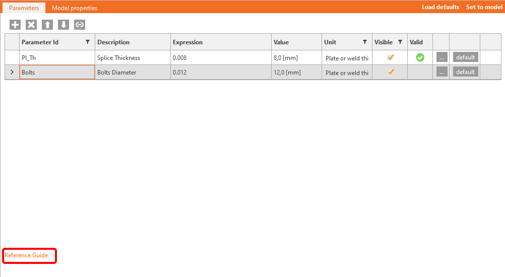
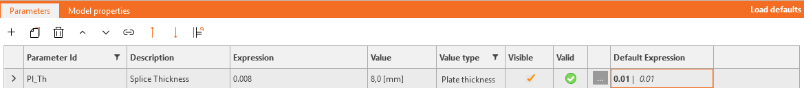
Enable the Developer tab. Then, as mentioned in the previous example - Parametric design in IDEA StatiCa Connection - Basics (01), adjust the thickness, visibility, default thickness, and the warning. All the necessary steps are mentioned below.

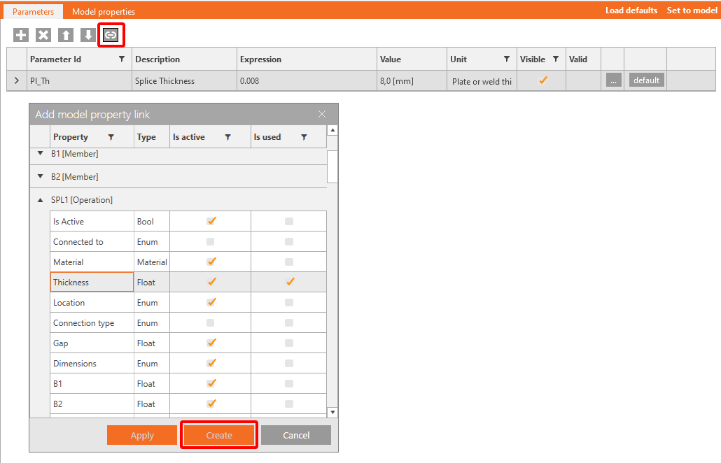
To enable link between the operations and parameters is necessary to add property link between the objects.
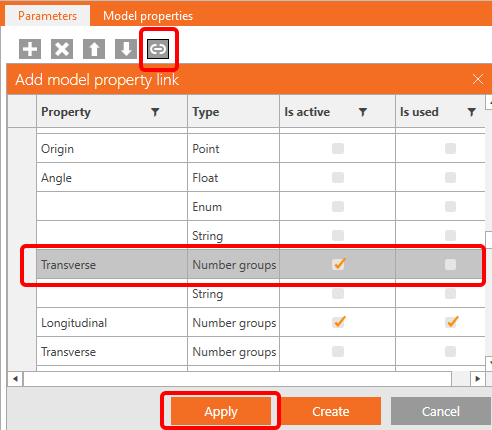
Spacing Transverse
This parameter will set up the transverse distance between the bolts. Fill in the fields according to the provided picture.
Enter the equation GetBoltDiameter('SPL1',0)*GetSettingValue('Design.Bolts.Detailing.Wall') to obtain the recommended distance value between the bolts and the web.

Loading the default settings will result in a change from 50 mm to 36.8 mm.
Transverse
If you want to work with the dataset, you have to use a correct data inputs in the field Transverse. The input will look like this: 0.0368; -0.0368.

To enable this step, you need to use the operation "Concat". Fill in Concat(Spacing_transverse,';','-',Spacing_transverse).

Finally, link the Transverse parameter with operations SPL1 and SPL2.
Number of rows
Address the name "Number_of_rows" as a further parameter. Enable visibility for actual parameter.

Distance of bolts in the longitudinal direction
Address the name "Distance_bolts" as a further parameter. Enable visibility for actual parameter.

Distance to the center of the joint
This parameter will help you to set the whole length of the plate. Set the values according to the picture.
Set also the value GetBoltDiameter('SPL1',0)*GetSettingValue('Design.Bolts.Detailing.Edge') to the default Expression as two times the diameter of the bolt.

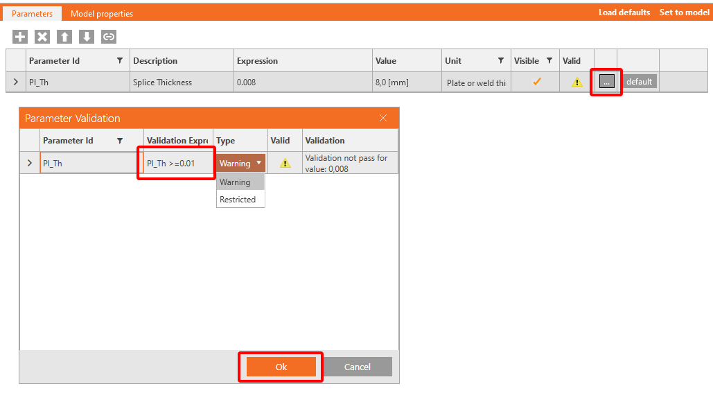
You also want to display a Warning if the value is less than two diameters. For this purpose, click the button with three dots (4) to open the Parameter Validation window and enter the expression First_row_distance>=GetBoltDiameter('SPL1',0)*GetSettingValue('Design.Bolts.Detailing.Edge').
The predefined settings give a hint and prevent errors during the design procedure.

Distance to the end of the plate
Similar to the previous parameter, we create the following parameter for the distance to the edge of the plate.
For the default value set the expresion GetBoltDiameter('SPL1',0)*GetSettingValue('Design.Bolts.Detailing.Edge').

For the warning, set the expresion End_distance>=GetBoltDiameter('SPL1',0)*GetSettingValue('Design.Bolts.Detailing.Edge')

Longitudinal
You have all the necessary data to fill in the Longitudinal field properly.
The following data set will enable create a chain of values. Insert into expression: Format('{0} {1}*{2}', First_row_distance,Distance_bolts,Number_of_rows-1)

Link this parameter to the to field of the same name in both operations SP1 and SP2.
Plate length
In the Operation Splice plate, the length of the splice is defined by the B1 and B2 values.
As you have previously determined the longitudinal distances between bolts, you can set these values for B1 and B2 in the background by adding them together.
Add a new Parameter Plate_length with the expression End_distance + First_row_distance + (Number_of_rows - 1) * Distance_bolts - see picture.
This parameter has to be linked to the B1 and B2 values in both operations SP1 and SP2.

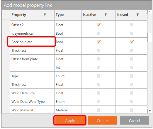
Backing plate
The last parameter you want to govern is the appearance of the backing plate.
You must create a boolean parameter with the value True/False, set it as visible, and link to the corresponding item.

You should see all linked parameters as follows

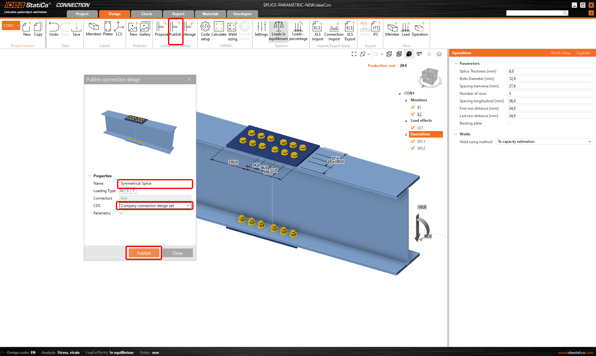
2 Publish the template
You symmetrical splice joint can be shared among other company users.
Go to the Design tab-->Publish-->Adress name. The Parametric box is automatically checked.
3 Get even more from Parametric
You have finished the parametric design procedure in IDEA StatiCa Connection from the Basic to Advanced level. Enjoy the feeling and apply it most to your projects.
Do you need to optimize your joints? Create or analyze joints in bulk? Learn more using parameters in Grasshopper, software dedicated to parametrizing your tasks.
Descargas adjuntas
- Splice-Parametric_full.ideaCon (IDEACON, 51 kB)