SAP2000 BIM link for the structural design of a steel member (EN)
1 How to activate the link
BIM link activation for SAP2000 (v23 and newer)
BIM link activation for SAP2000 (v22 and older)
2 How to use the link
Open the attached project in SAP2000 and run the geometrically nonlinear analysis (GNA)(1) to get results. This type of analysis is predefined in SAP2000 due to the fact that the buckling lengths are not defined in the Member application and additional internal forces from the global imperfection ought to be covered in this analysis.
Select the members 42, 43, 44, 48 (2). The connections are automatically exported with selected members.
Go to menu item Tools and choose the IDEA StatiCa plugin (3).
The Checkbot pops up, and you select New, desired Design code (EN), and finally Create project.
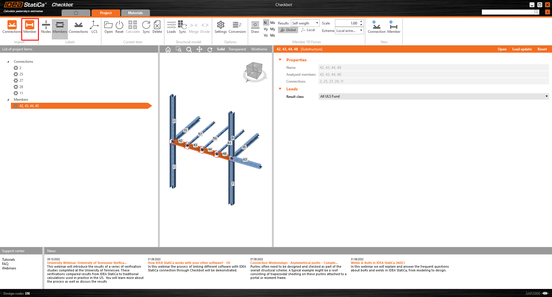
Confirm the selection by clicking on the Member item. All selected members with related connections are exported to Checkbot.
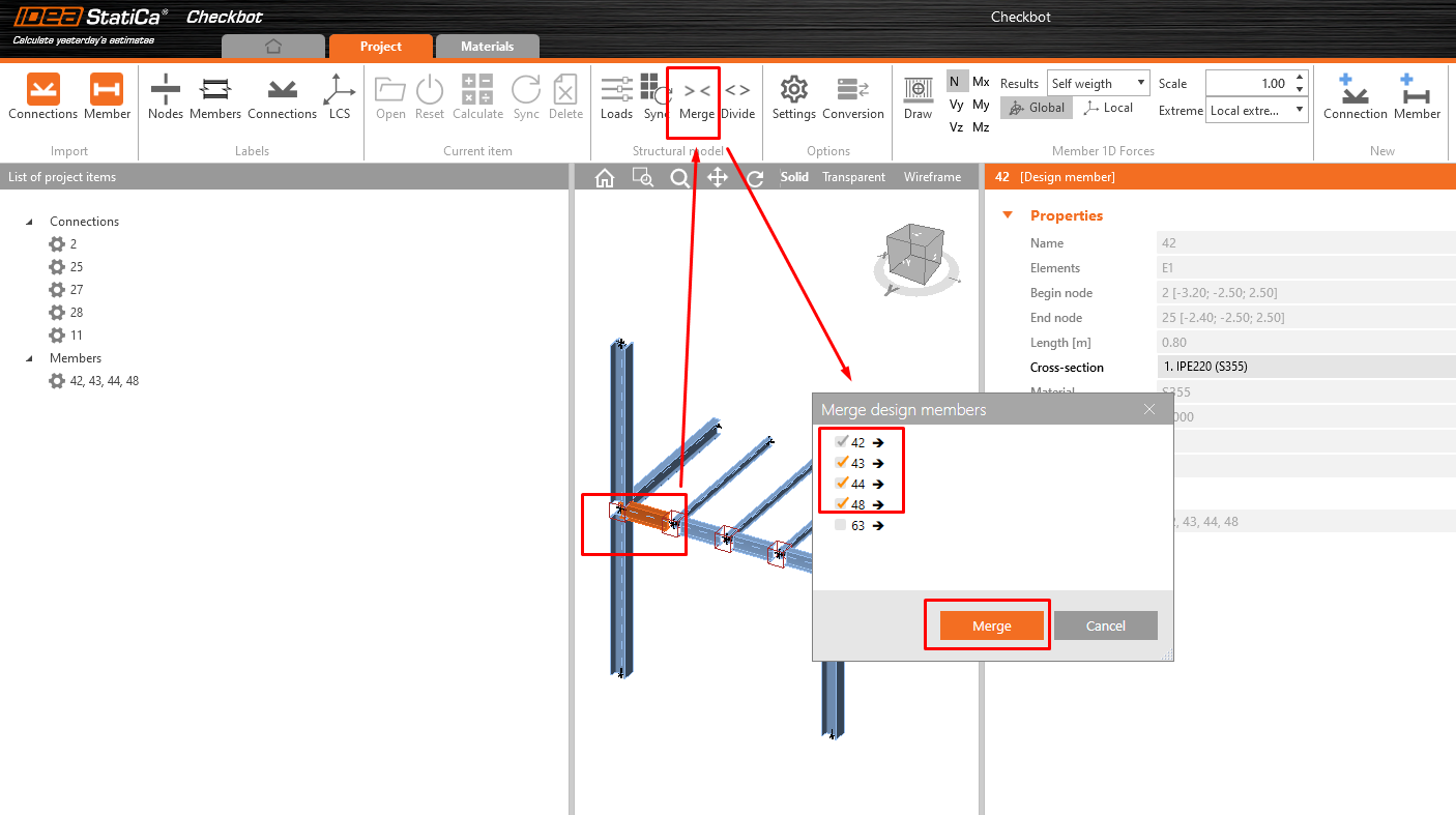
To merge all the selected parts into one member, click on one of the members in 3D scene and then the button Merge. A new small window appears; select items 42-48 and click Merge.
Do the same for columns 1+2 and 7+8
3 Design
Now you can run the module Member by right-clicking on the selected member and clicking on Open.
Select the first joint Nr.2 and click Edit connection; a window with the module Connection appears.
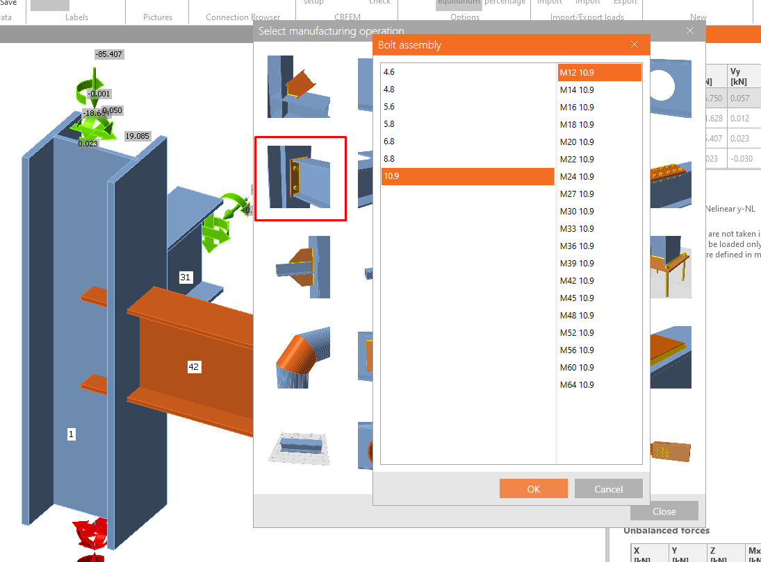
For both of the horizontal beams, please apply the operation End plate and Fin plate with the following settings.
Click on the Save button and close the window.
Now select the end joint Nr. 11 and apply operations according to the following pictures.
Fin plate on member 35
End plate on member 63
End plate on member 42
Wideners on member 42
Click on the Save button and close the window.
Select one of the middle joints 25,27,28 and click on Edit connection.
Apply the operation Fin plate according to the following picture.
Click on the Save button and close the window.
Select the remaining two joints and apply the former configuration to them using the button Apply.
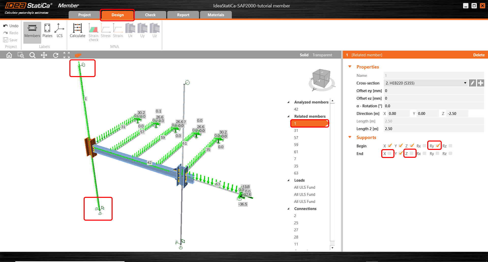
Next thing is to set correct boundary conditions. To all related members are assigned the hinges where all three degrees of freedom (X, Y, Z) are set as a default. The settings of the boundary conditions ought to respect the FEM in SAP2000. For Member 1 restrain the rotation Ry at the beginning and release the translation X, Z at the end of the member.
Perform the steps for member 7 in the same way.
Due to the global model is the member 63 suspended by an inclined tensile member. Set the support only in the Z direction.
4 Check
Move to the Check tab and Run MNA (Materially Nonlinear Analysis). After finishing the analysis display the Equivavalent stress on the members.
Move to LBA (Linear buckling analysis) and Run the analysis. You receive the eigenmodes with the critical factors for each of them. These factors are sorted out gradually and the most significant is mainly the first one.
Move to GMNIA and set the imperfection values into the second mode. The value of 16 mm is calculated according to the code as described in the article Imperfections. Run the GMNIA.
Display the results of the GMNIA and turn on the Strain check. Zoom in closer to the fin plate where is visible the places of the plastification.
5 Report
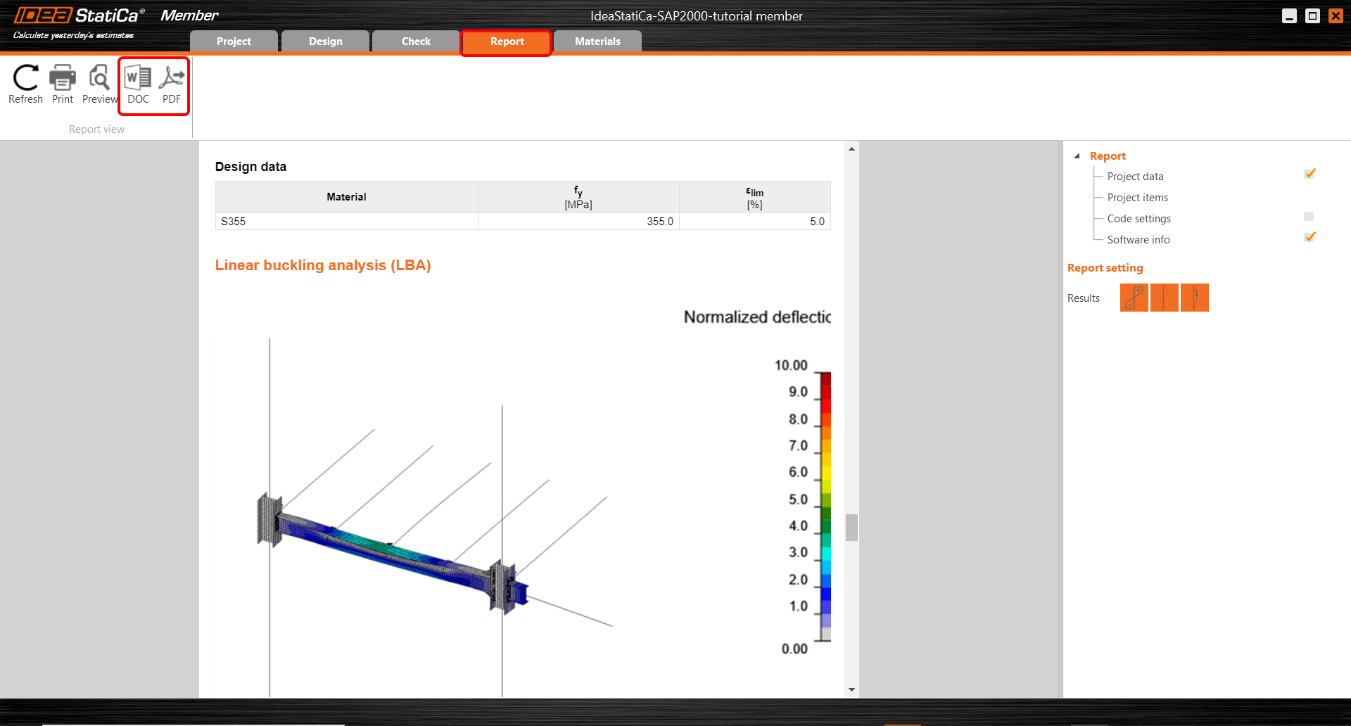
At last, go to the tab Report. IDEA StatiCa offers a fully customizable report to print out or save in an editable format.
Now you have designed, analyzed and code-checked the critical member in the application Member.
6 Synchronize models
Synchronization for Member applications is identical to the same process for SAP2000 BIM link with IDEA StatiCa Connection.
Want to improve your skills? Visit our Campus
Téléchargements joints
- SAP 2000 BIM link member design.zip (ZIP, 73,3 MB)


