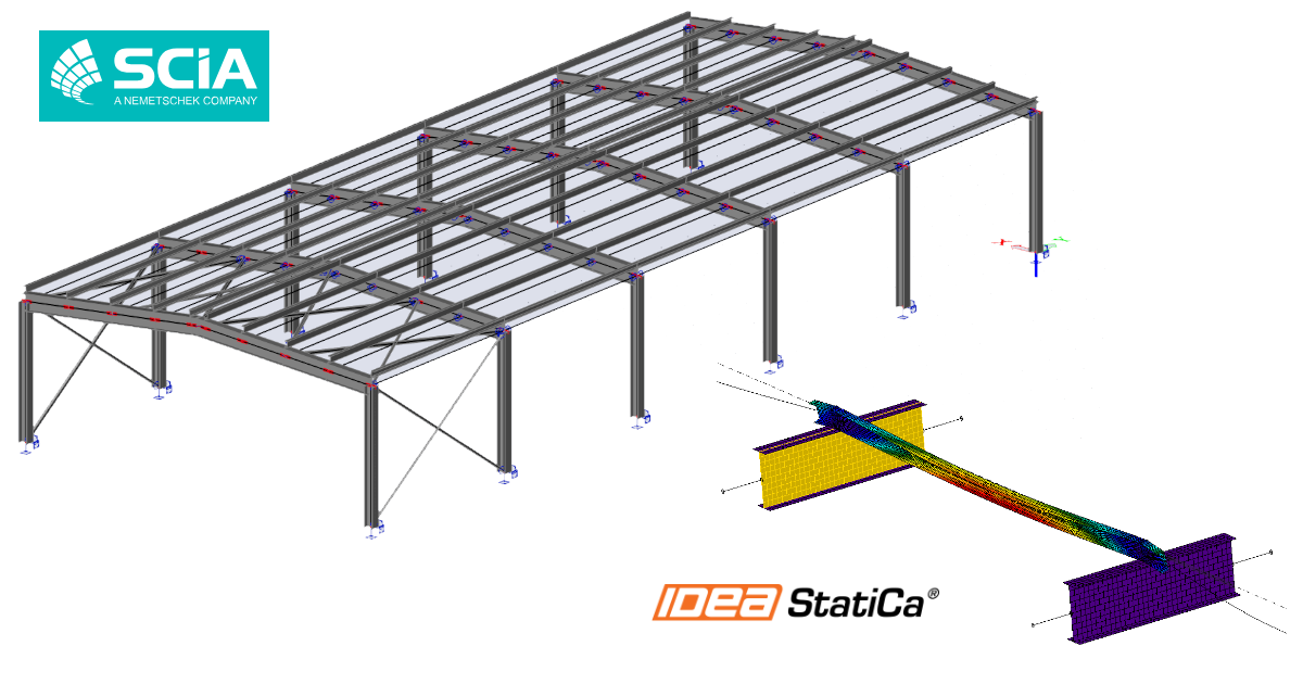
SCIA Engineer BIM link for steel member design (EN)
How to activate the link
- Download and install the latest version of IDEA StatiCa
- Make sure that you are using a supported version of your FEA/BIM solution
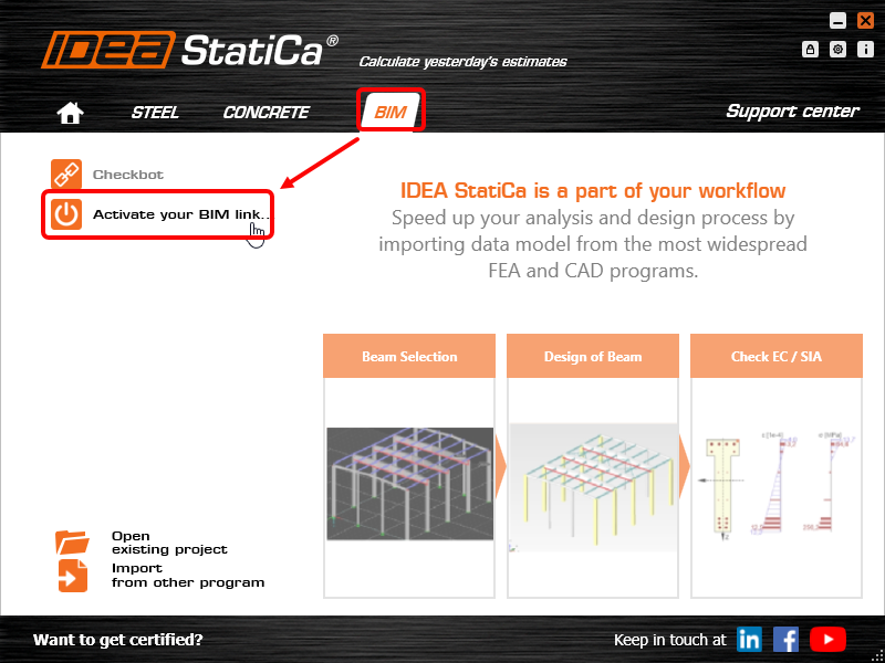
IDEA StatiCa integrates BIM links into your FEA/BIM solutions during its installation. You can check the status and activate more BIM links for software installed after in the BIM link installer.
Please note that some FEA solutions require additional steps to fully activate their BIM link to IDEA StatiCa.
Open IDEA StatiCa and navigate to the BIM tab and open the BIM link installer (Activate your BIM link...).
A notification "Do you want to allow this app to make changes to your device?" may appear, if so, please confirm with the Yes button.
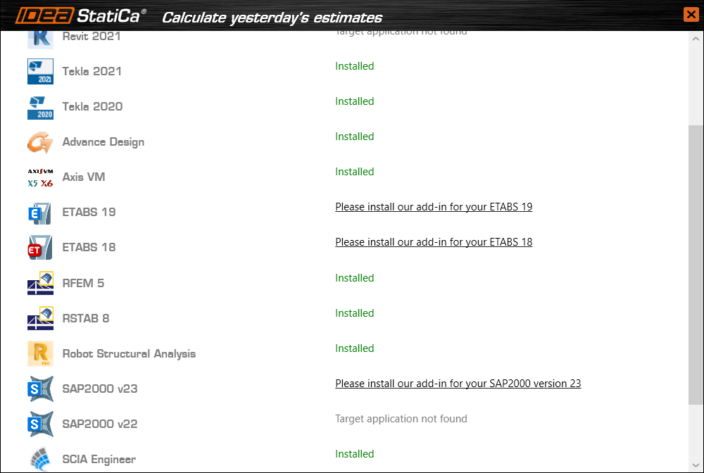
The BIM link for the selected software (if found) is installed. The screen also tells you the status of other BIM links that may have already been installed.
How to use IDEA StatiCa Checkbot
Download the attached project, open it in SCIA Engineer, and run the calculation to get the internal forces over the structure.
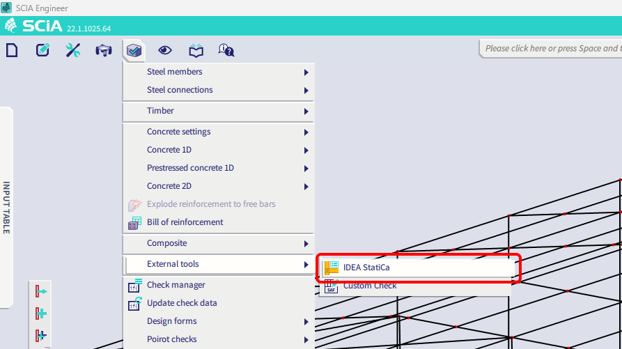
After that, run the IDEA StatiCa Checkbot application.
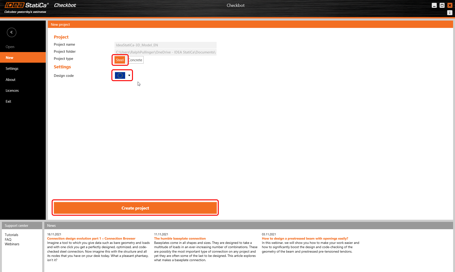
Select the New option with project type Steel and design code EN. Then select Create project.
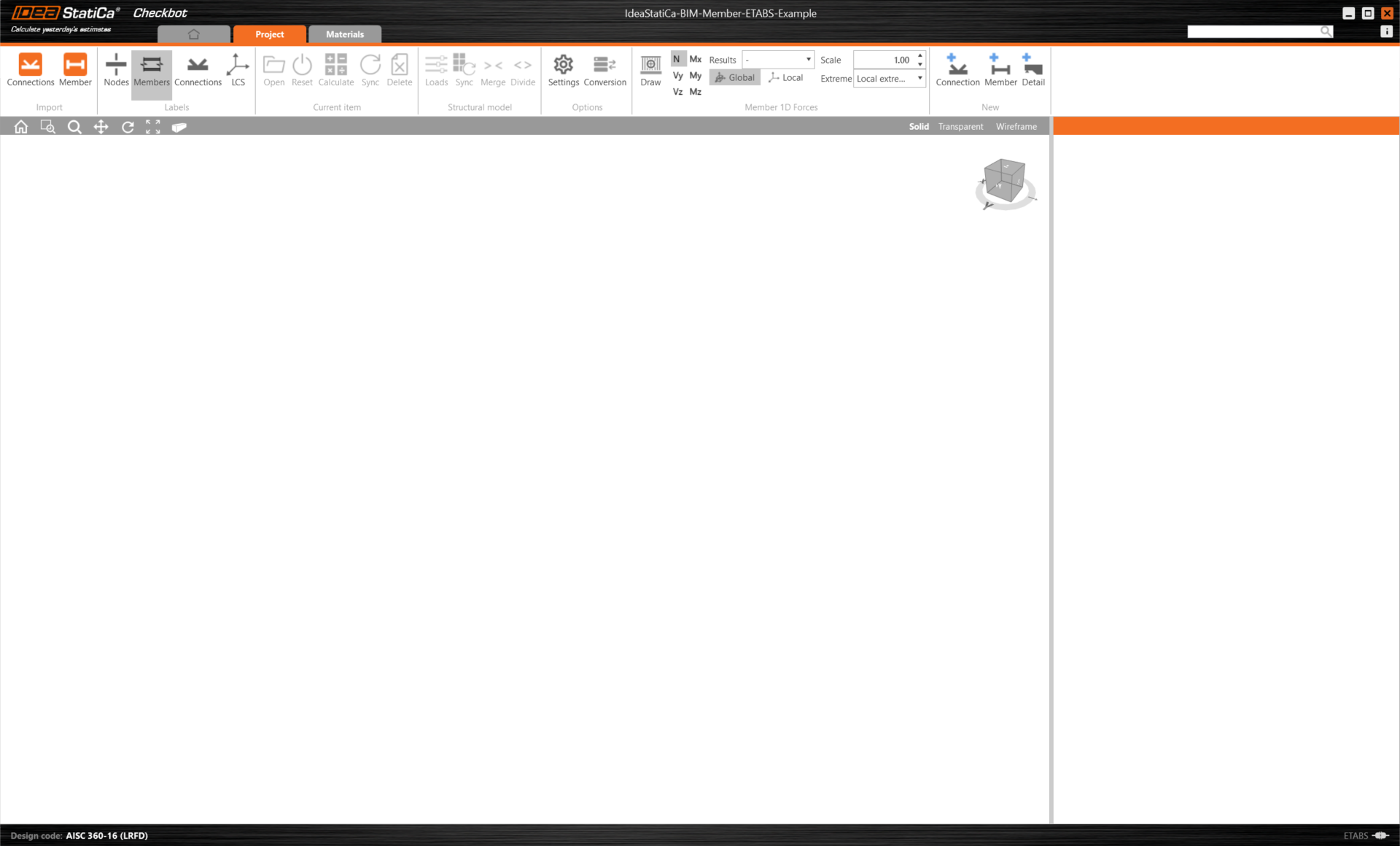
The new Checkbot project is ready to import connections and members from SCIA Engineer.
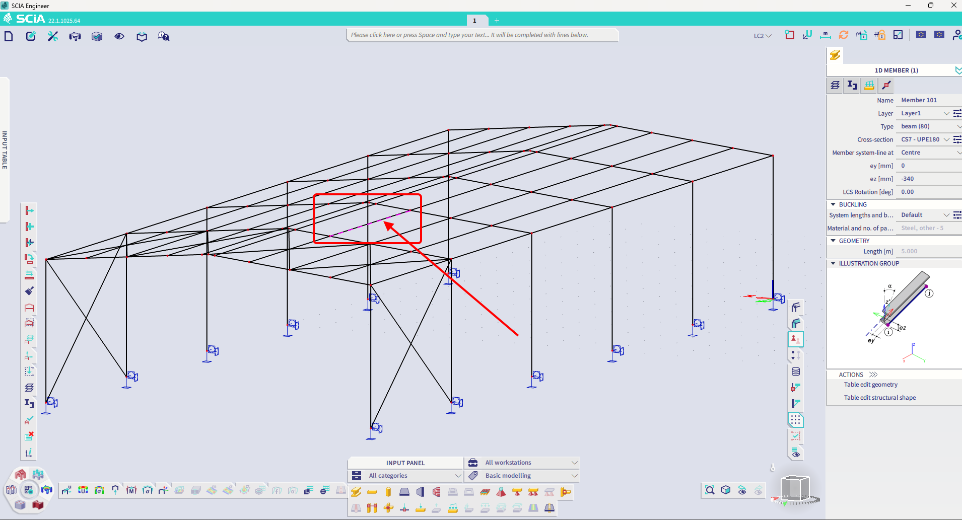
In SCIA Engineer, select one of the inside members, as shown in the picture.
Import
Then in Checkbot select Member.
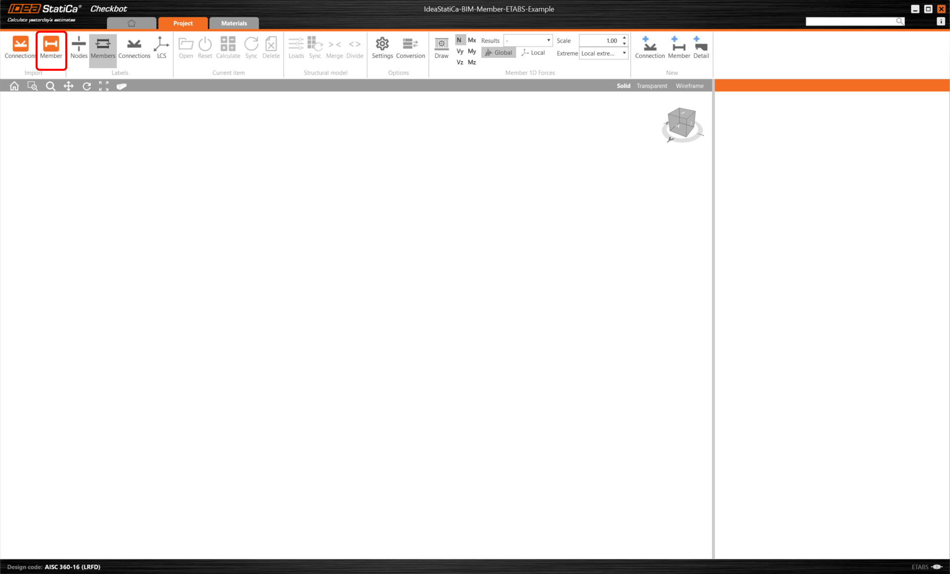
This will import the beam and its load effects into Checkbot - with the exact coordinates, orientations, and section sizes as per the FEA/BIM model.
Please note that your node and member numbering might be different, also the elevation position of the member itself.
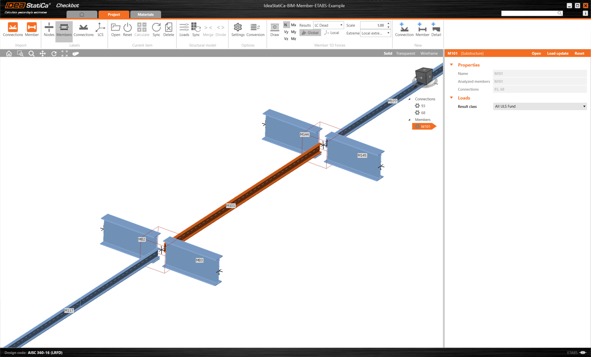
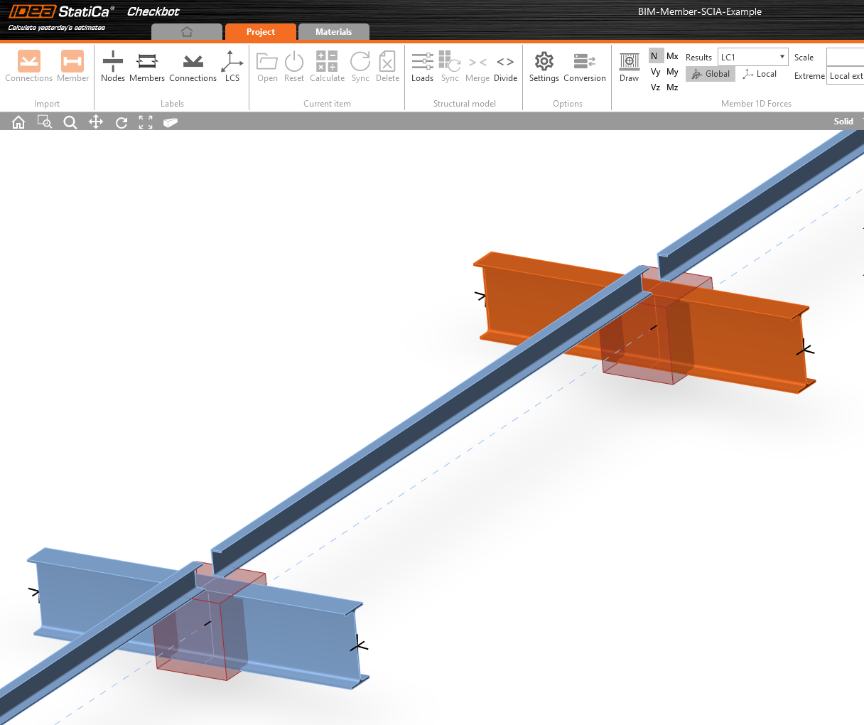
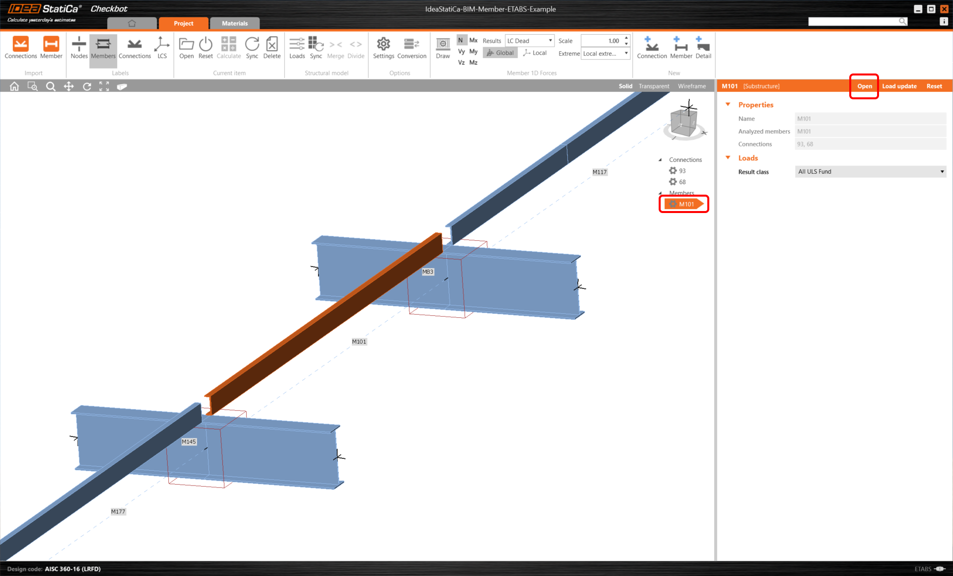
As you can see, the selected member with all related members was imported.
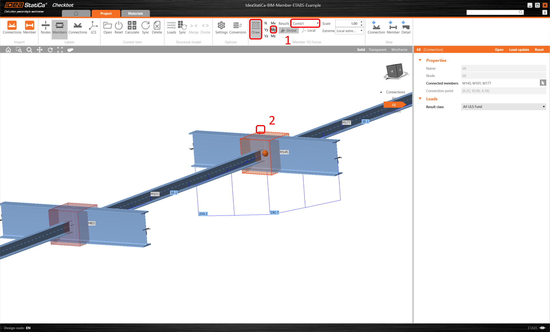
You can check the internal forces. Select Draw, then the desired internal force and combination, then left-click on the connection box and follow the steps below in the picture.
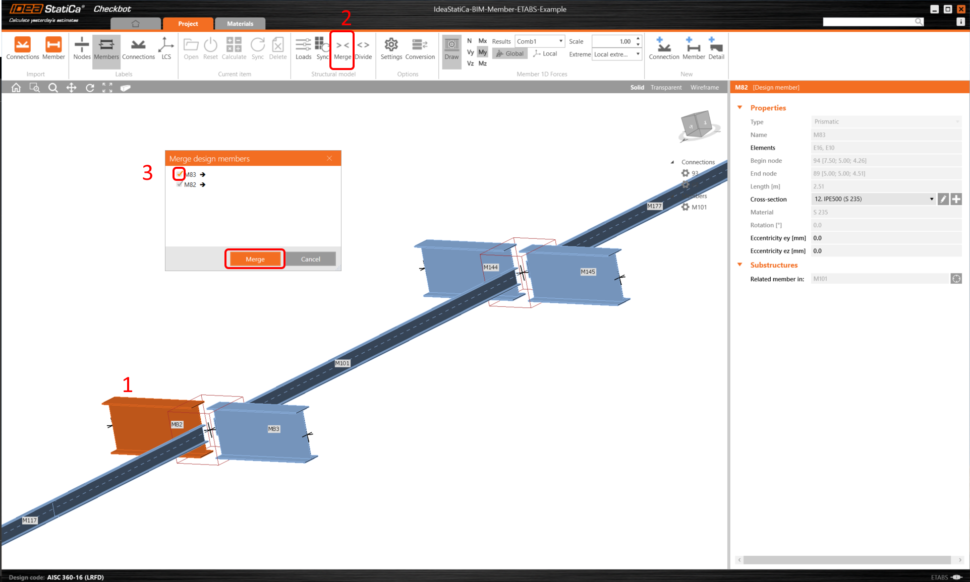
Elements can be merged together directly in Checkbot, then in the Member application; they will be a single continuous element.
Merge both perpendicular related members. Left-click the I-profile M-82, select Merge operation, then tick the M83 box in the merge design window, and follow the steps as shown in the picture.
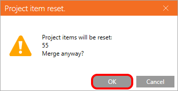
In this window, you will see an informative alert about the operation that will occur, accept it.
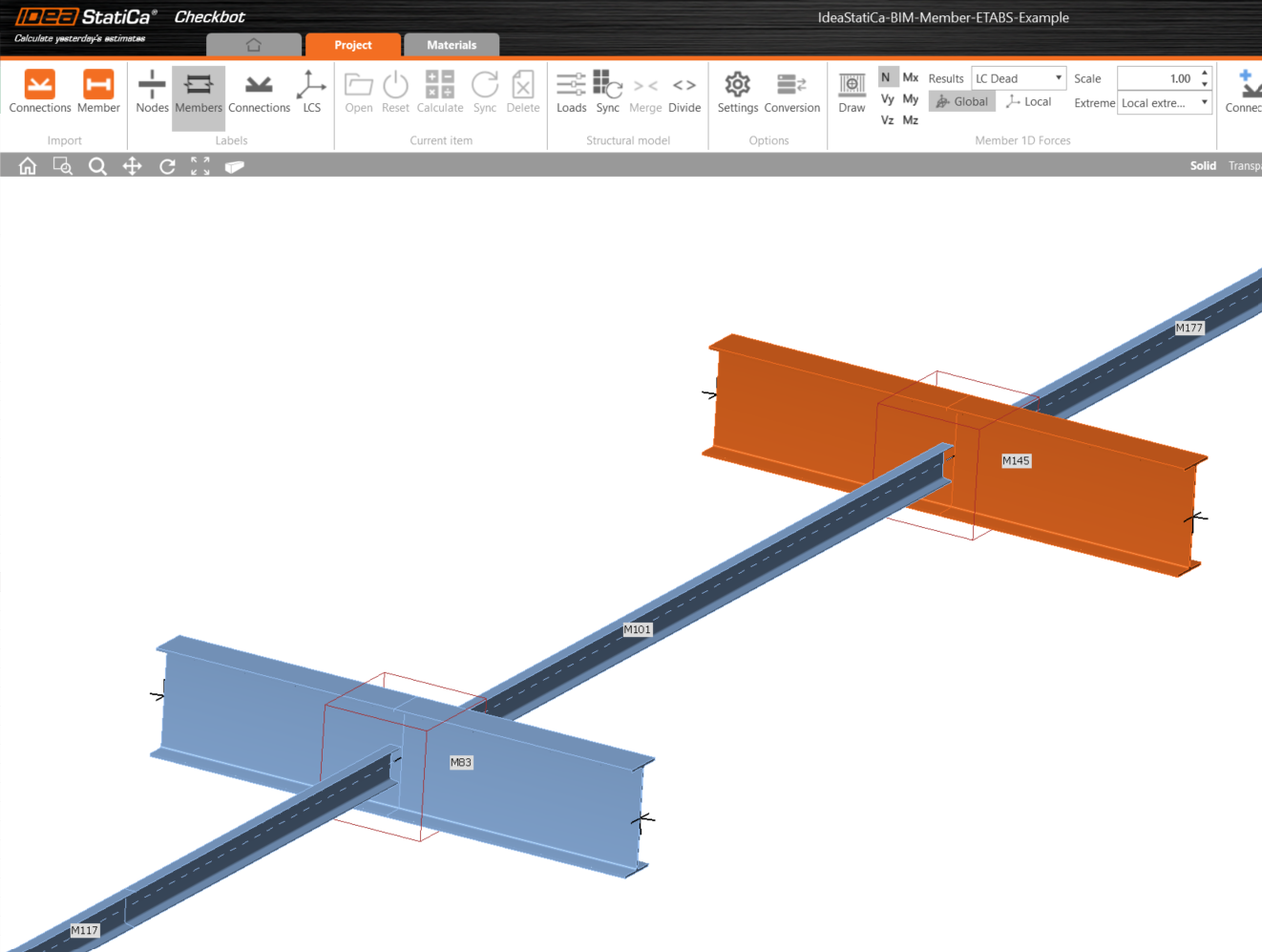
Make the same merging action for another group of I-profile. After changes, our model should look as in the following pictures.
- member with imported eccentricities
- member without imported eccentricities
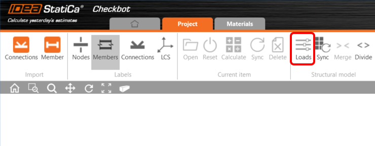
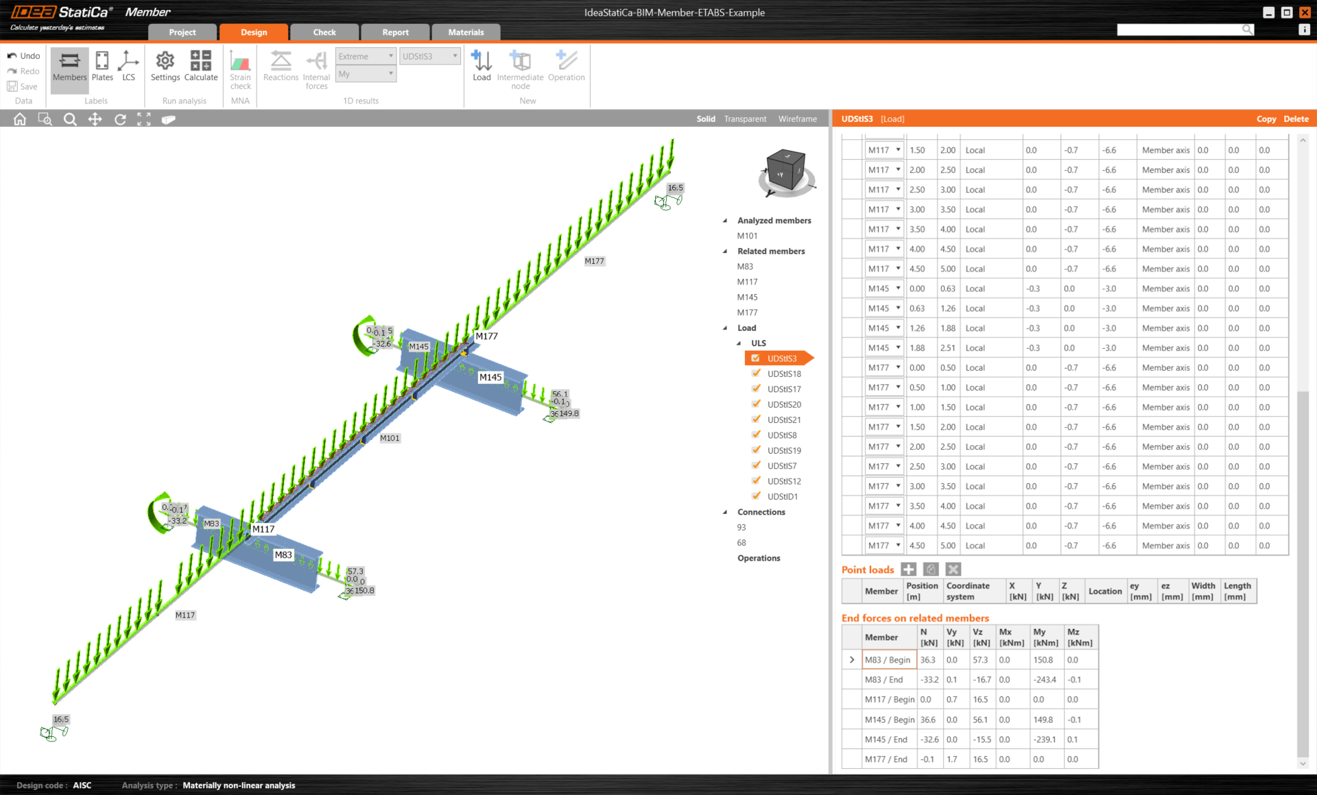
You can control what load case or combination will be loaded to the Member application by clicking on Loads and managing Result classes for checks.
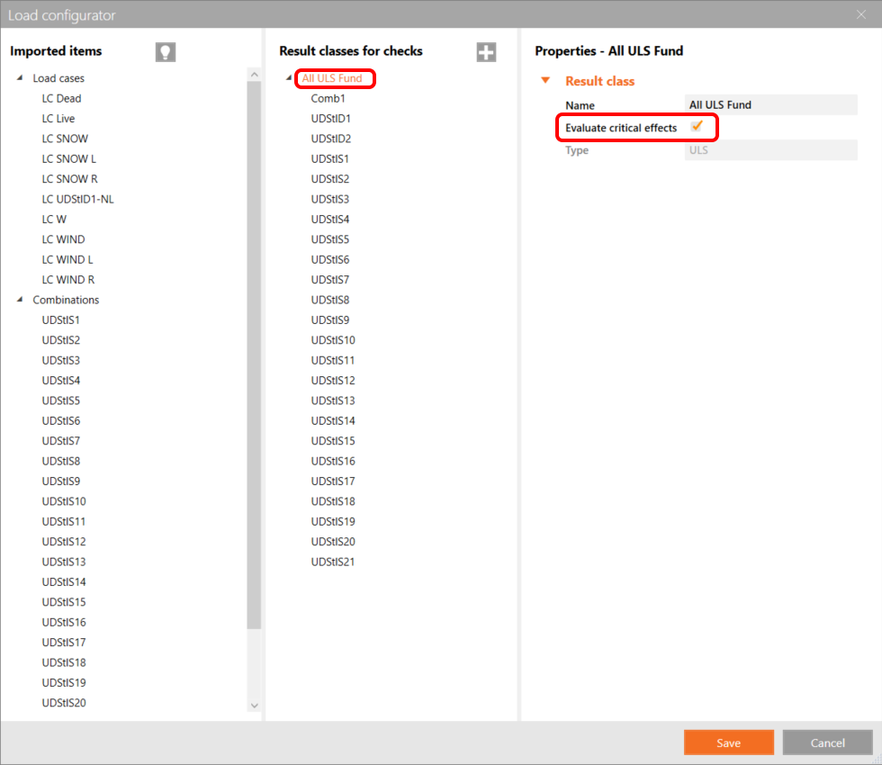
Here in Load Configurator, you can add load cases for the member application. Please notice by default the Evaluate critical results function is enabled, which filters critical combinations to speed up the calculation. You can turn it off and all combinations will be included in the calculation.
Members modul
Now we can open the Member application. Just left-click on Open.
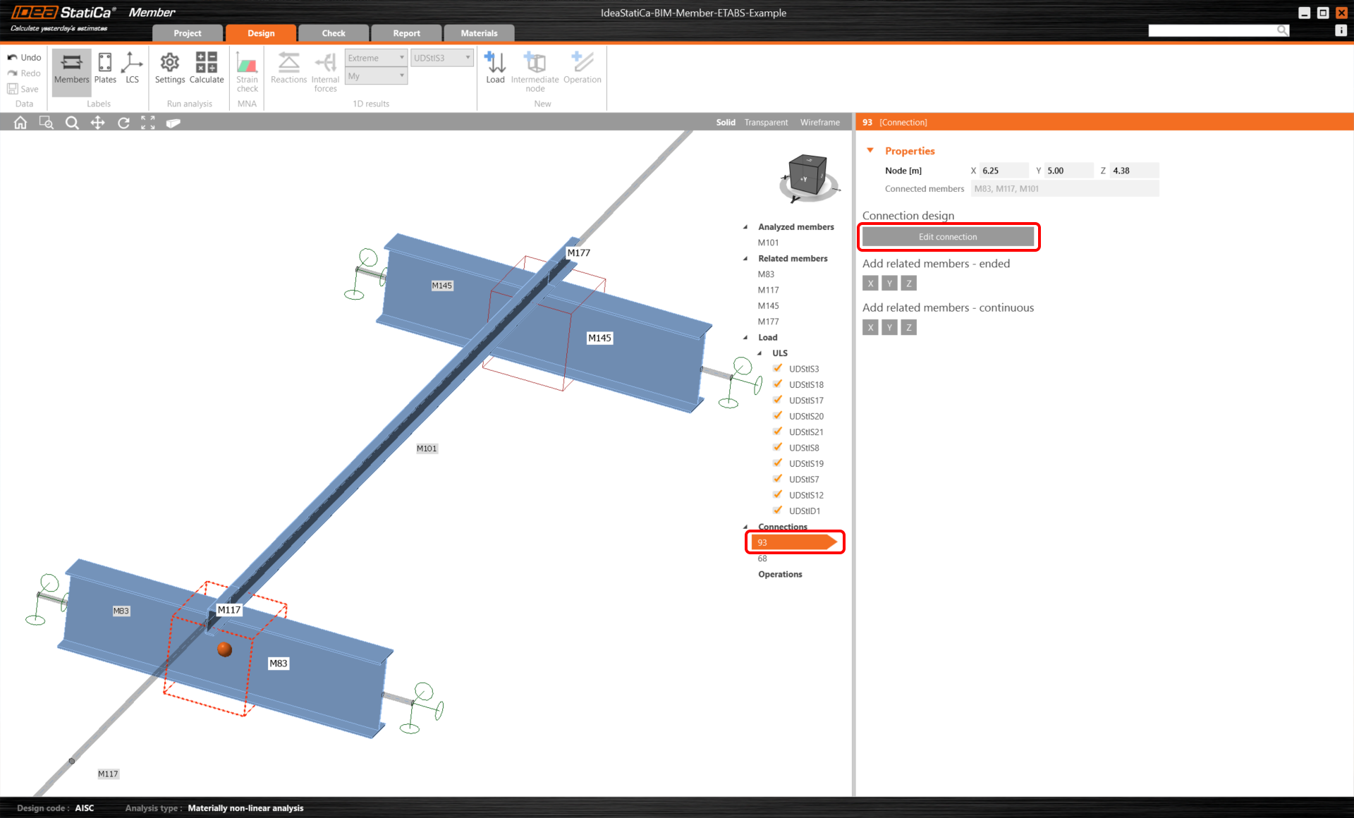
Here you can see our Member application.
In the beginning, let us design the joints of the member U-profile, so please select the first connection and click on Edit connection. As you can see now I-profiles are represented by one continuous element, thanks to the merging we made.
We have successfully imported and checked a purlin from the SCIA Engineer.
Csatolt letöltések
- BIM-Member-SCIA-Example.esa (ESA, 3,7 MB)
- BIM-Member-SCIA-Example.zip (ZIP, 2 MB)