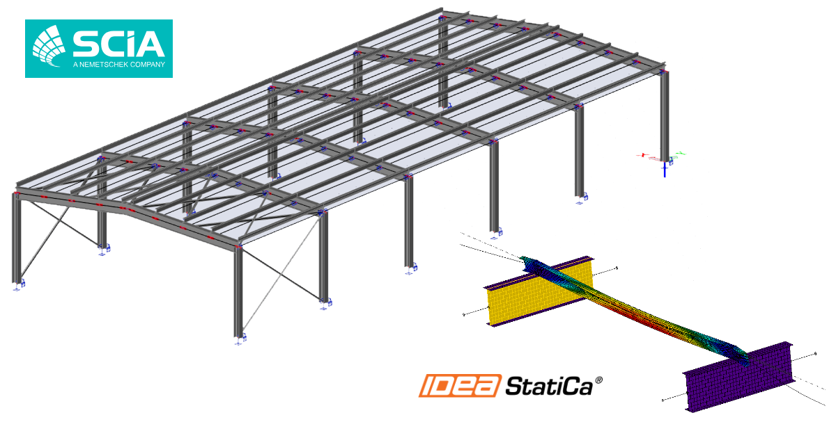
SCIA Engineer BIM link for steel member design (EN)
Comment activer le lien
- Téléchargez et installez la dernière version de IDEA StatiCa
- Vérifiez que vous utilisez une version autorisée de votre solution MEF/BIM
IDEA StatiCa intègre les liens BIM dans vos solutions MEF/BIM lors de l'installation. Vous pouvez voir le statut et activer autres liens BIM pour des logiciels installés aussi plus tard dans l'outil d'installation des liens BIM.
Veuillez noter qu'il faut des étapes supplémentaires pour activer des liens BIM de quelques solutions MEF avec IDEA StatiCa.
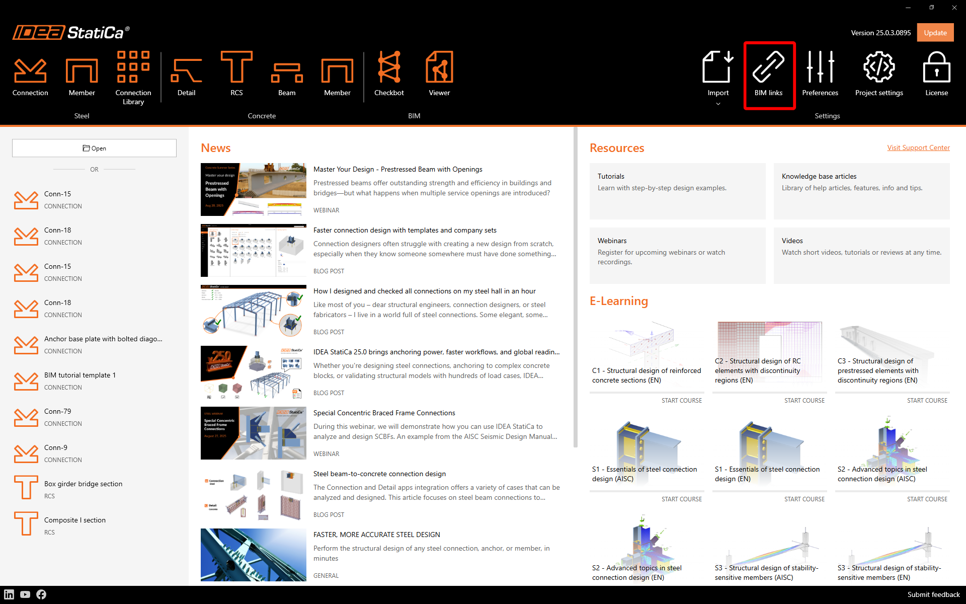
Ouvrez IDEA StatiCa et allez à l'onglet BIM et ouvrez l'outil d'installation des liens BIM (Activation du lien BIM...).
Une notification avec le texte « Voulez-vous autoriser cette application à apporter des modifications à votre appareil ? » peut apparaître. Dans ce cas, veuillez confirmer avec le bouton Oui.
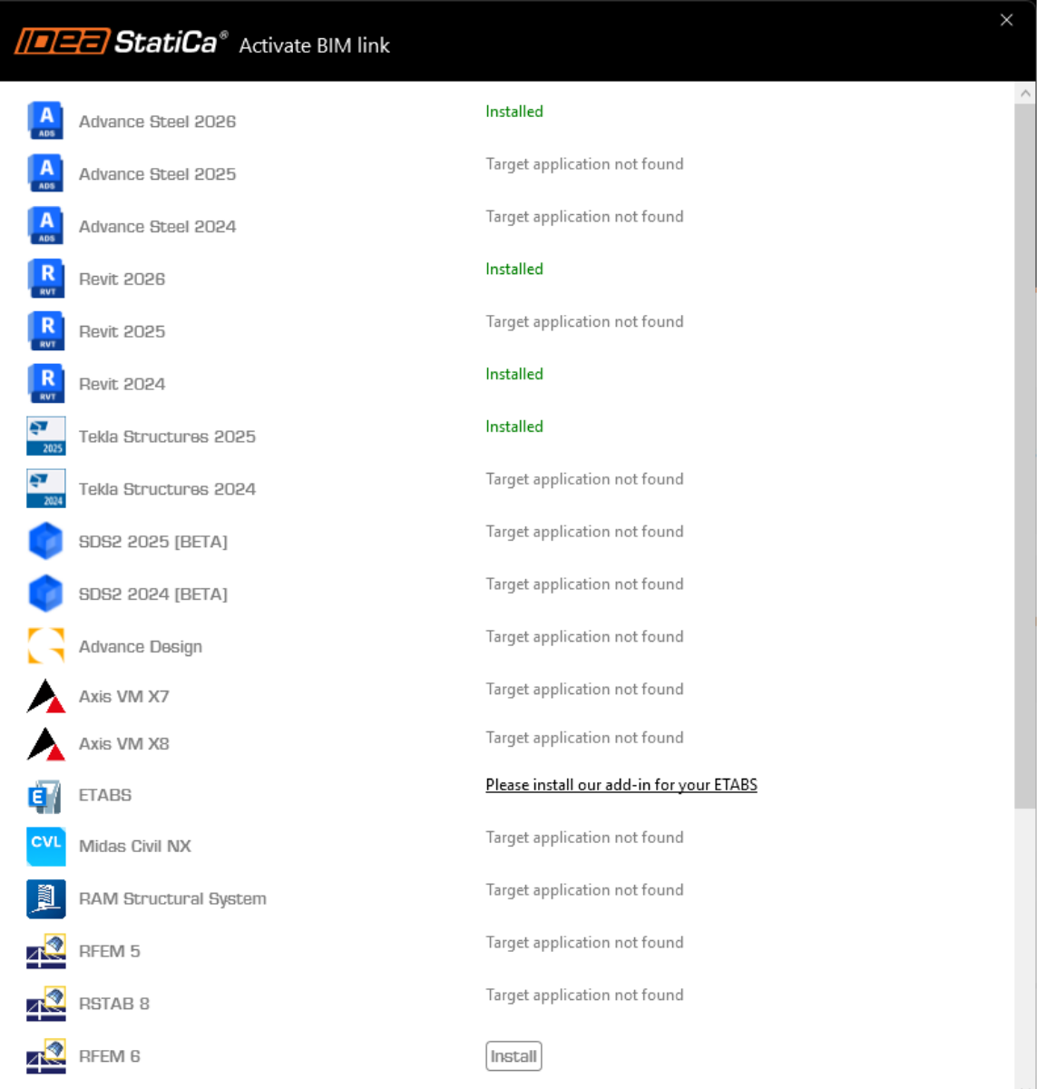
Le lien BIM pour le logiciel sélectionné (si trouvé) sera installé. L'écran vous montrera aussi le statut d'autres liens BIM qui peuvent être déjà installés.
How to use IDEA StatiCa Checkbot
Download the attached project, open it in SCIA Engineer, and run the calculation to get the internal forces over the structure.
After that, run the IDEA StatiCa Checkbot application.
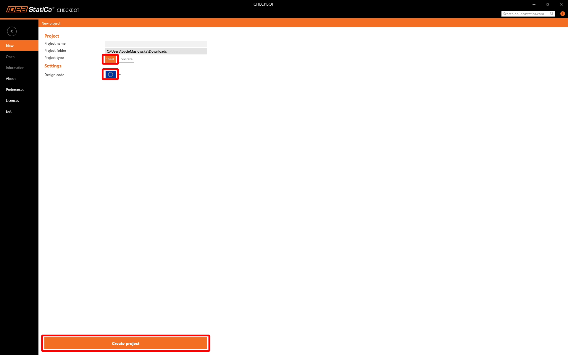
Select the New option with project type Steel and design code EN. Then select Create project.
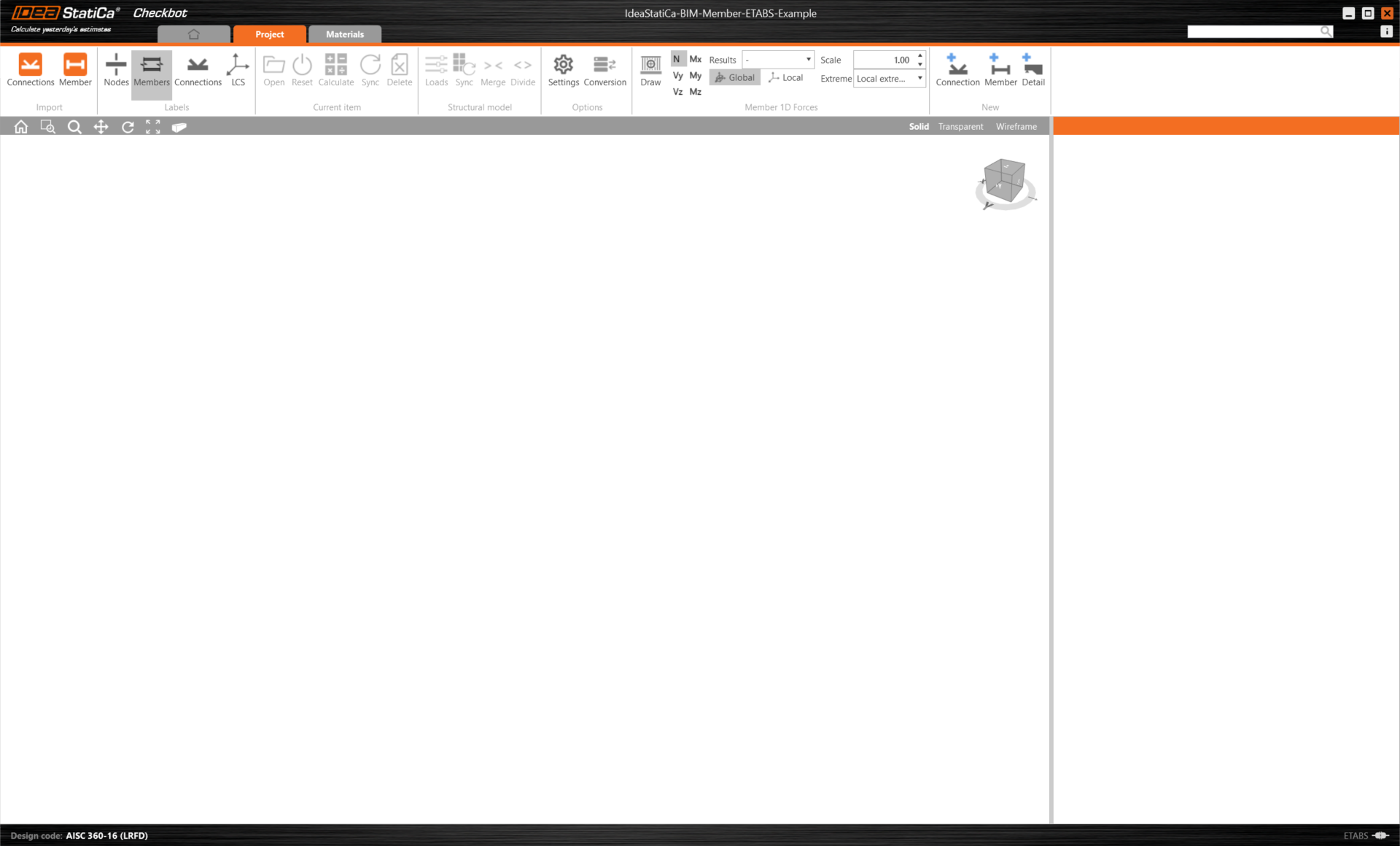
The new Checkbot project is ready to import connections and members from SCIA Engineer.
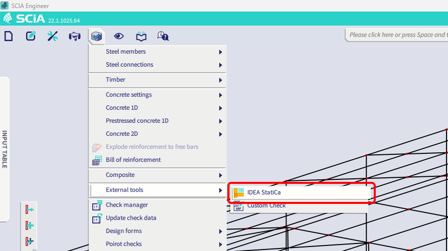
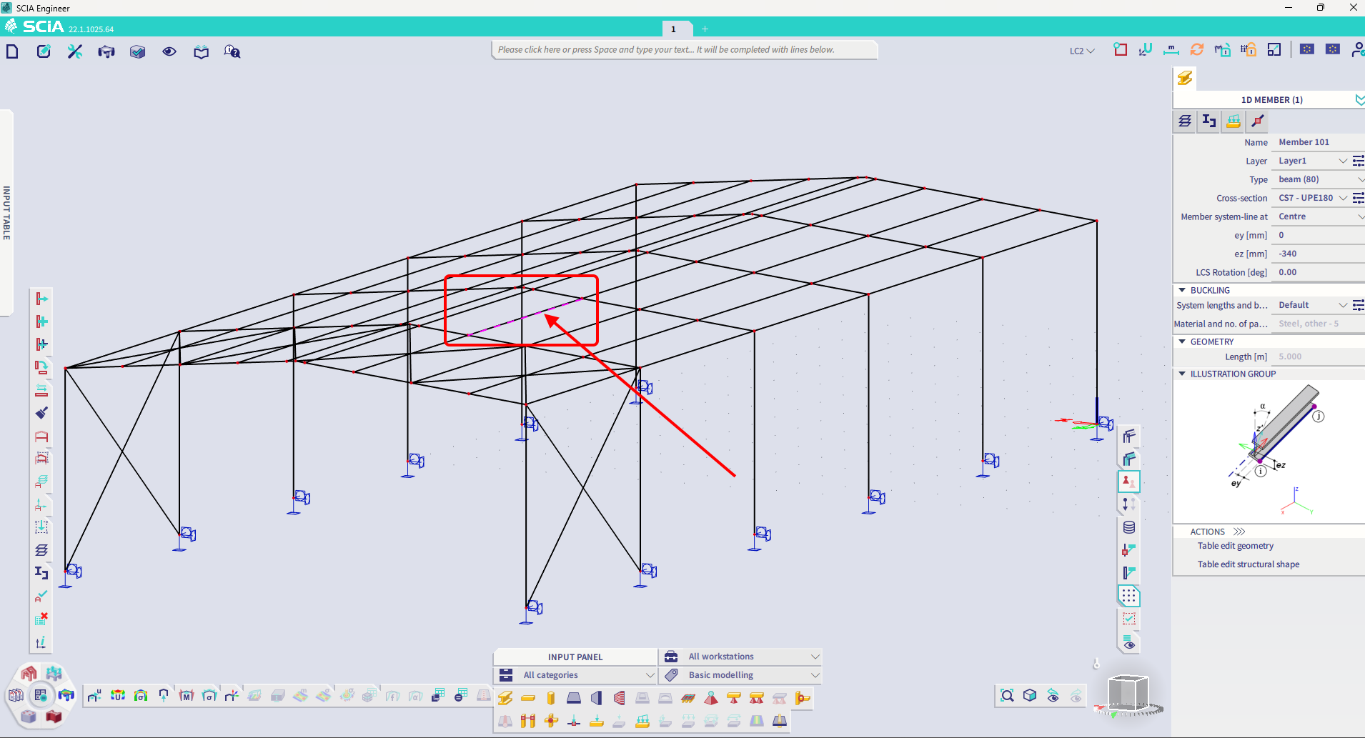
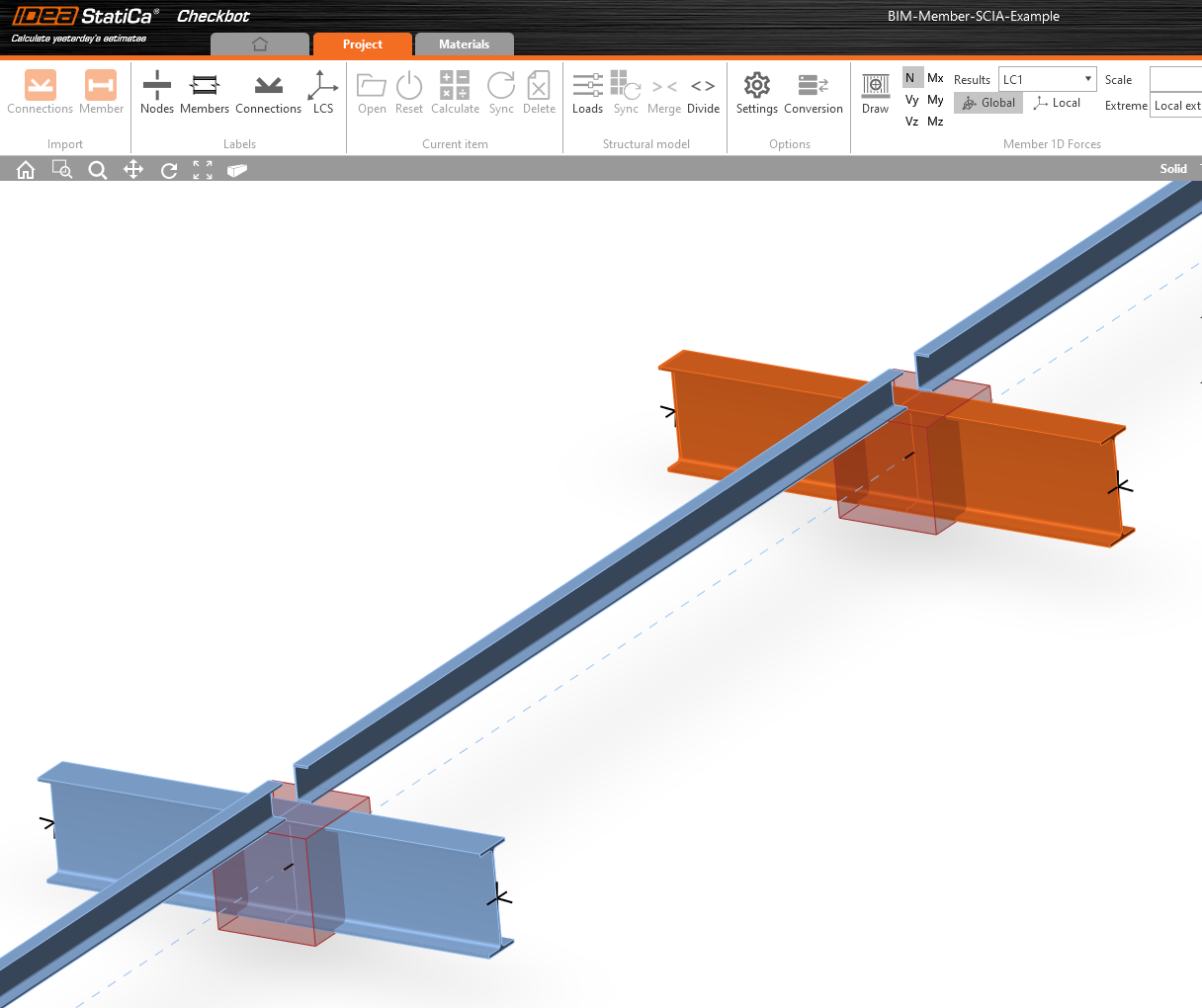
In SCIA Engineer, select one of the inside members, as shown in the picture.
Import
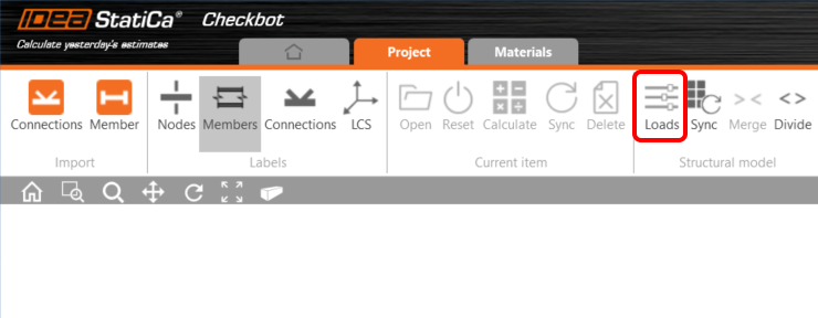
Then in Checkbot select Member.
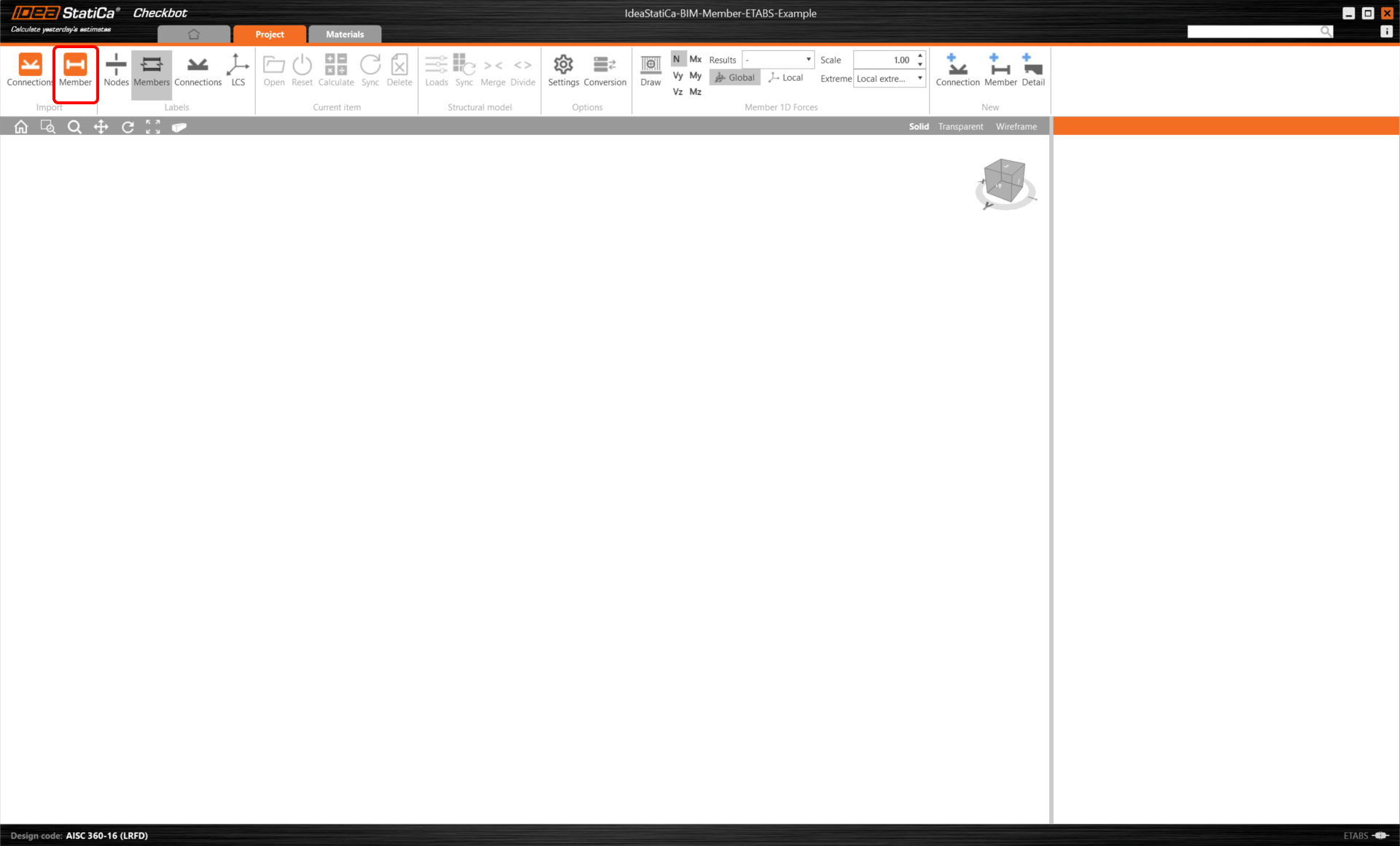
This will import the beam and its load effects into Checkbot - with the exact coordinates, orientations, and section sizes as per the FEA/BIM model.
Please note that your node and member numbering might be different.
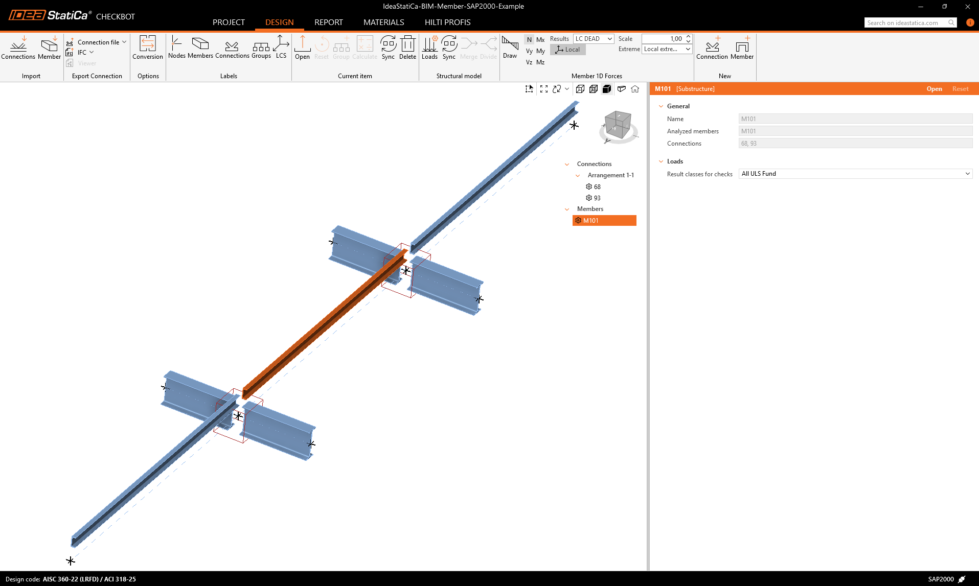
As you can see, the selected member with all related members has been imported.
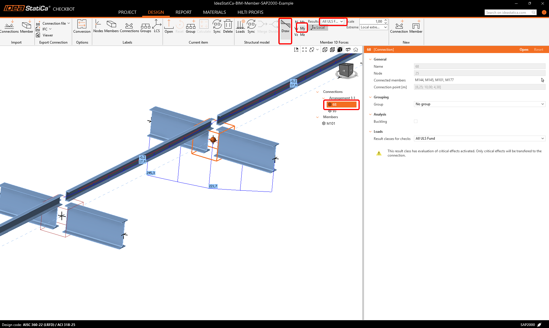
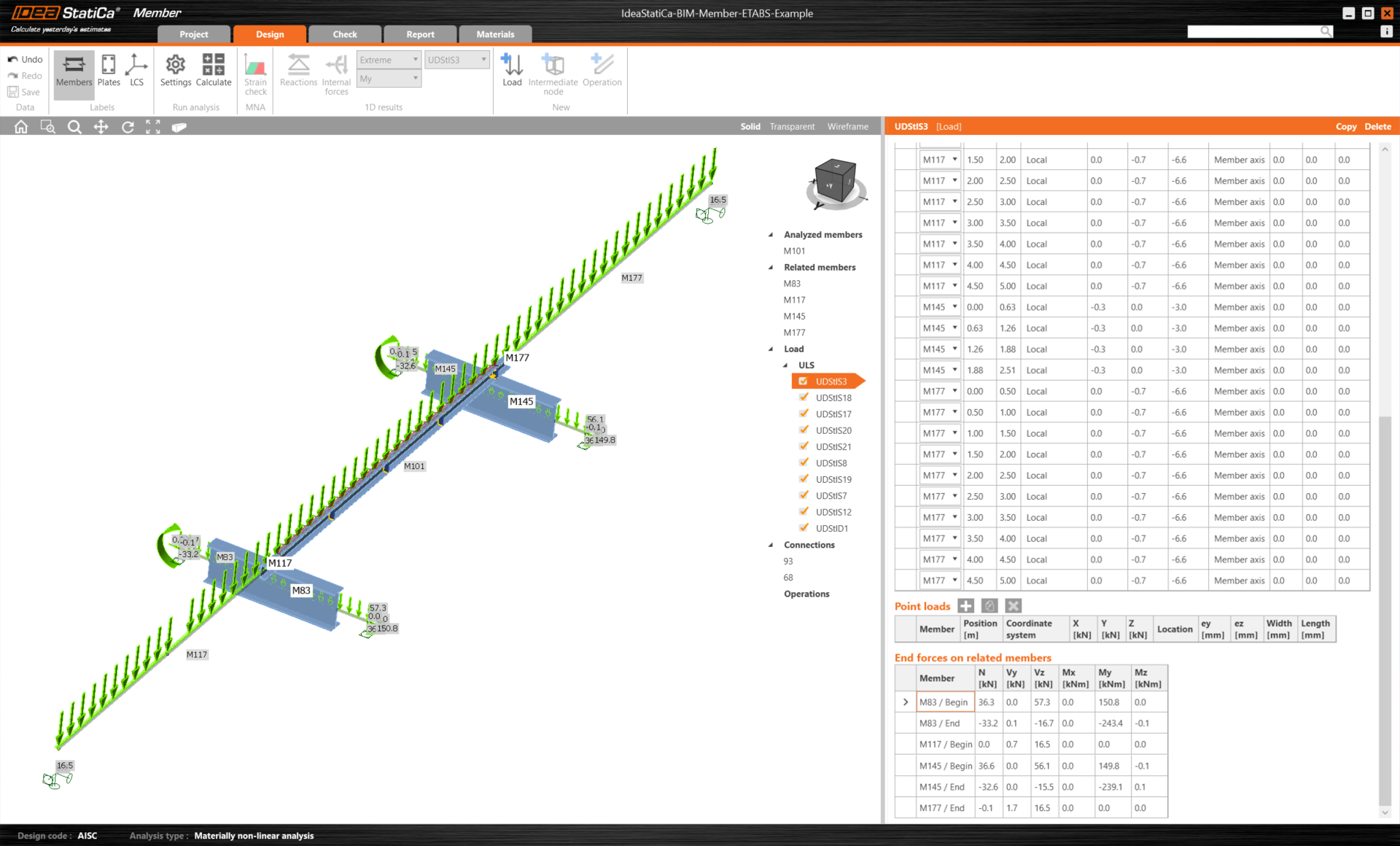
You can check the internal forces. Select Draw, then the desired internal force and combination, then left-click on the connection box, and follow the steps below in the picture.
Elements can be merged together directly in Checkbot, then in the Member application; they will be a single continuous element.
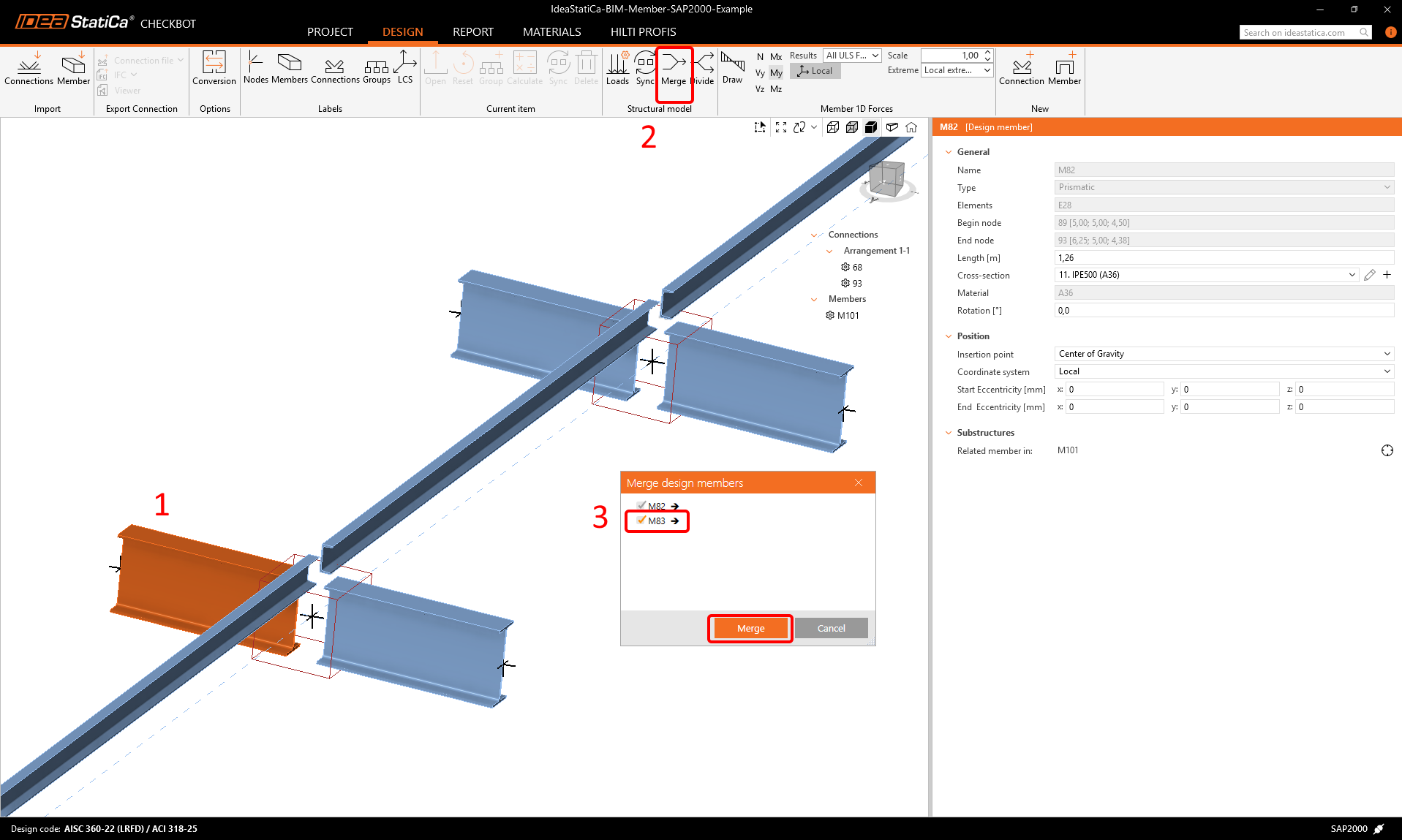
Merge both perpendicular related members. Left-click the I-profile M-82, select Merge operation, then tick the M83 box in the merge design window, and follow the steps as shown in the picture.
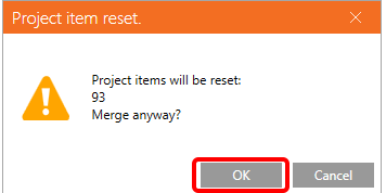
In this window, you will see an informative alert about the operation that will occur, accept it.
Make the same merging action for another group of I-profile. After changes, our model should look as in the following picture.
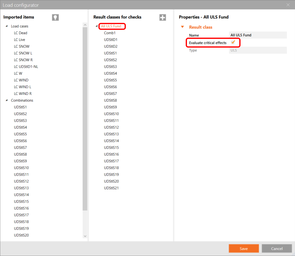
You can control what load case or combination will be loaded to the Member application by clicking on Loads and managing Result classes for checks.
Here in Load Configurator, you can add load cases for the member application. Please notice by default the Evaluate critical results function is enabled, which filters critical combinations to speed up the calculation. You can turn it off and all combinations will be included in the calculation.
Members modul
Now we can open the Member application. Just left-click on Open.
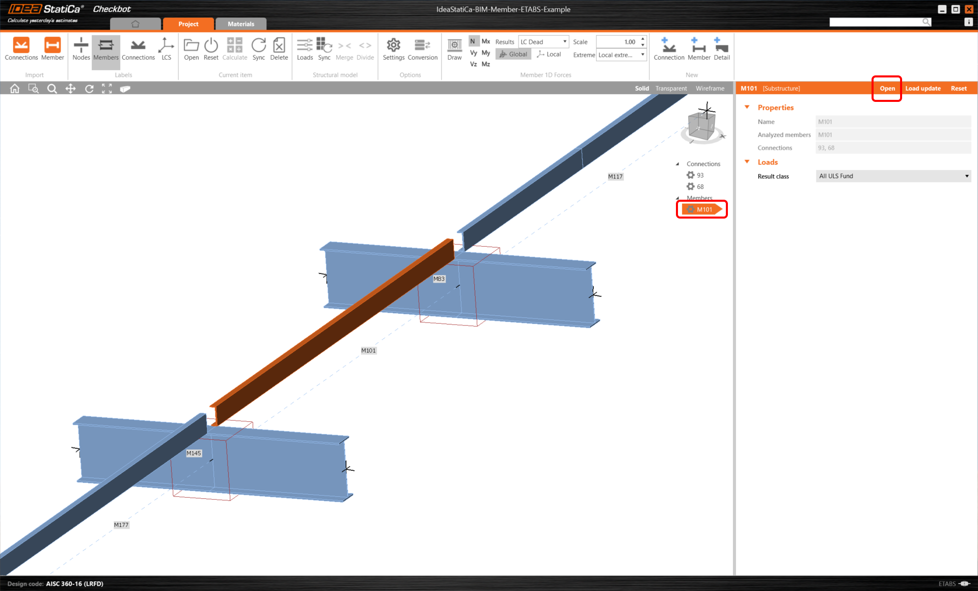
Here you can see our Member application.
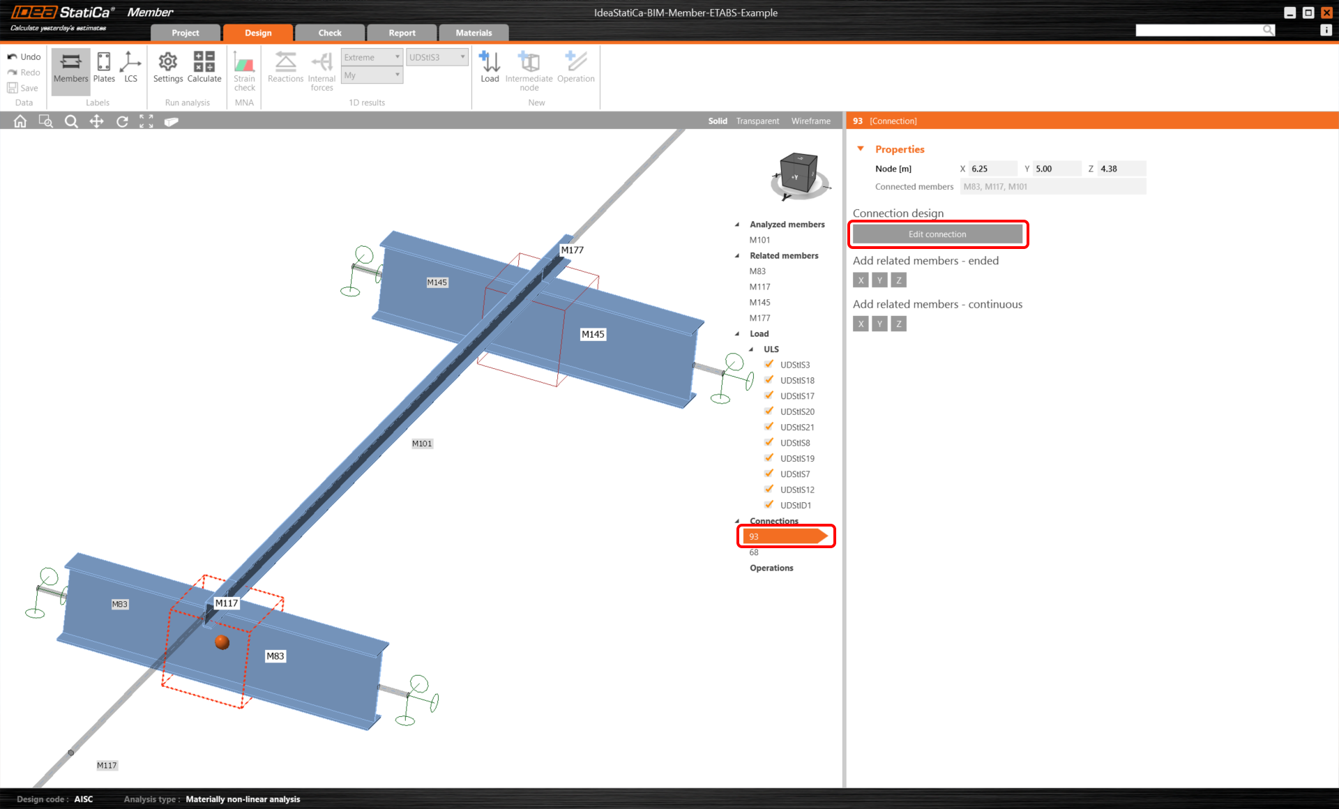
In the beginning, let us design the joints of the member U-profile, so please select the first connection and click on Edit connection. As you can see now I-profiles are represented by one continuous element, thanks to the merging we made.
We have successfully imported and checked a purlin from the SCIA Engineer.
Téléchargements joints
- BIM-Member-SCIA-Example.esa (ESA, 3,7 MB)
- BIM-Member-SCIA-Example.zip (ZIP, 2 MB)