Achieve the impossible, specifically in anchoring design
One could say, "Just design what the standard explicitly allows us." But let’s do a reality check: that’s simply not how it works, whether for the tight spaces or technical and architectural requirements. And so, anchoring that could be considered "on edge" (figuratively) – or better said, specific types of anchoring – can be seen all around us. Many cases are precisely calculated and verified with more advanced methods (even if it may have taken an excessively long time). However, many cases have probably not been assessed as thoroughly as they deserve.
IDEA StatiCa has been changing and pushing forward the design of steel connections, steel and concrete members, and concrete details for some time now. It's not about simplification of the workflow through computerized calculation, it's mainly about the innovative methods that allow us to design the previously unthinkable. Our latest achievement, the release of IDEA StatiCa Detail for 3D, again extends the design possibilities further than before.
Whether you belong to the group that struggles with anchoring designs for days or relies solely on experience but then doesn't sleep soundly, read on.
Doors to new possibilities
If you are involved in anchoring structures, you can probably think of several cases that have given you a hard time. Here are a few examples that we have recently identified as very difficult to design using only standard practices. But, with the help of our tools IDEA Statica Connection and Detail, it is becoming possible to design in a relatively reasonable amount of time.
Figure 1: Multiple anchoring into one concrete block
- Anchoring near the edge – Anchoring close to the edge is almost impossible to design without reinforcement due to the way concrete fails (cone failure and others). Assessing anchoring in reinforced concrete is labor-intensive on its own – see this article for more details: You no longer have to struggle with anchoring design. However, Detail (3D mode) is specifically designed for such cases – reinforced concrete. By adding reinforcement, we can prevent failure modes that would otherwise occur in plain concrete. At the same time, using an advanced FE method (3D CSFM) and implementing it in Detail makes a very complex task relatively simple.
Figure 2: Examples of anchoring near to an edge in Connection (including steel members) and in Detail (including reinforcement)
- Multiple anchoring close together – The problem that we have with close anchoring is that the cones interact with each other. No guide can directly advise us on how to assess these cases. In the commonly used literature, whether EN or fib guide, we find more or less only conditions and limitations that we can conservatively consider. They simply advise us to use distances that allow us to assess cones individually. But as soon as we don't fit into these conditions, we're doomed. However, in Detail, since we have an advanced FE-based method, we can analyze the complex behavior.
Figure 3: Multiple anchoring into one the wall
- Multiple anchoring in general (bridge support on a common foundation) – A typical situation caused by wind load, where one column of a truss support is loaded by tension and the other by compression. There is a mutual interaction between the concrete cone from the group of tension anchors and the compressive loading from the other column. For such a case, Eurocode does not offer a satisfactory analytical solution, not only because it is inherently necessary to reinforce the concrete foundation, so more advanced analysis such as Detail and its 3D CSFM must be used.
Figure 4: Anchoring of a pipe bridge, designed by FEVIA s.r.o
- Consideration of existing reinforcement in renovations – Any renovations or extensions may be another interesting example of the use of anchoring in Detail, as, ideally, the existing reinforcement is included.
Problems that arise
To sum it up:
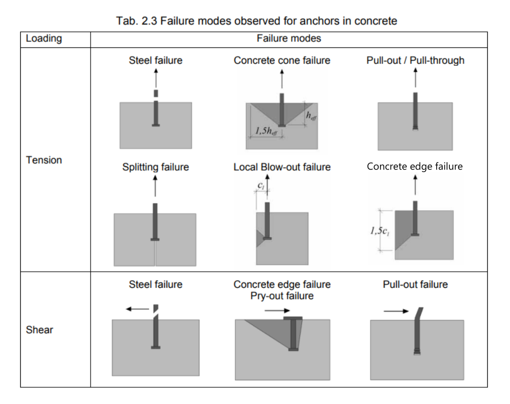
Eurocode specifies failure modes for both tension and shear for anchors and concrete:
Figure 5: Scheme of failure modes – Design of Steel-to-Concrete Joints Design Manual II
EN 1992-4 is specifically dedicated to the detailed assessment of plain concrete. Most of these concrete failures can be prevented by adding reinforcement, which is even necessary in some cases (see examples above). However, the standard no longer gives us clear guidance on how to deal with this.
Another problem arises when concrete cones interact with each other – Eurocode and other literature (fib bulletin 58) only give conditions for when and how these cones can be checked separately.
Figure 6: CEB-FIB: Bulletin 58 – Design of anchorages in concrete (2011), chap. 1.2
We know the issues that can occur during the design, but what to do about it? Give up or...
...find a solution.
The solution
Detail can solve the cases above very efficiently. It allows the assessment of the influence of reinforcement on the load capacity and also allows the assessment of the cases not covered by the standard. In combination with Connection, it is then possible to obtain comprehensive standard code checks for all types of failures.
Much has already been written about both applications, but it certainly doesn't hurt to add a brief comparison and a few resources for a deeper understanding of the methods:
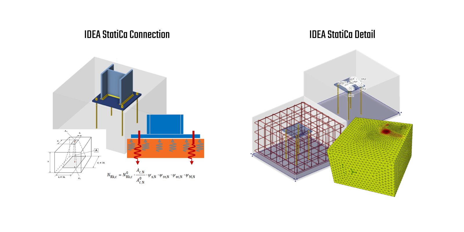
- IDEA StatiCa Connection – focused on assessing steel connections, including anchoring in concrete. The anchors are assessed according to empirical formulas in accordance with the standard. The concrete block is modeled using the "Winkler" scheme, so the possible assessment is for plain concrete only.
- IDEA StatiCa Detail – The model in Detail is from the final elements, including the reinforcement. Due to the basic assumption that all the tension is transferred by the reinforcement (in concrete, the tension is neglected), the solution is only suitable for reinforced concrete. Using 3D CSFM, we obtain the stresses of concrete and reinforcement/anchors, which are evaluated with limit values from Eurocode. In addition, we get a realistic idea of the behavior of the structure, such as stress flows and deformations. The 3D CSFM method included the effects of tri-axial stress.
Figure 4: Comparison between Connection and Detail (input and models)
As said, a combination of both is needed for a complete assessment. For efficient work, an import from Connection to Detail is enabled, including additional parameters and loads.
To understand the method, you can proceed to the Theoretical Background. To catch up with functionalities, go to the Release Notes.
What are you going to do?
3D Detail (with CSFM) represents a significant step forward, enabling the design of more complex cases with confidence. While some may feel apprehensive about this progression, the technologies at our disposal allow us to achieve more than ever before – so why not embrace their potential? Progress is both natural and inevitable.
At IDEA StatiCa, we see anchoring as just the beginning. It’s the first case we’ve fully verified, and we’re committed to expanding our focus to other challenges in the future.
The question is: Will you adapt to these advancements, or will you resist change?


