Autodesk Revit BIM-Verknüpfung für die Verbindungsbemessung (EN)
So aktivieren Sie den Link
- Downloaden und installieren Sie (als Administrator) die aktuelle Version von IDEA StatiCa
- Vergewissern Sie sich, dass Sie die unterstützte Version verwenden
IDEA StatiCa integriert den BIM-Link während der Installation automatisch in Ihre FEA-/BIM-Lösung. Sie können den Status überprüfen und weitere BIM-Links für nachträglich installierte Software im BIM-Link-Installer aktivieren.
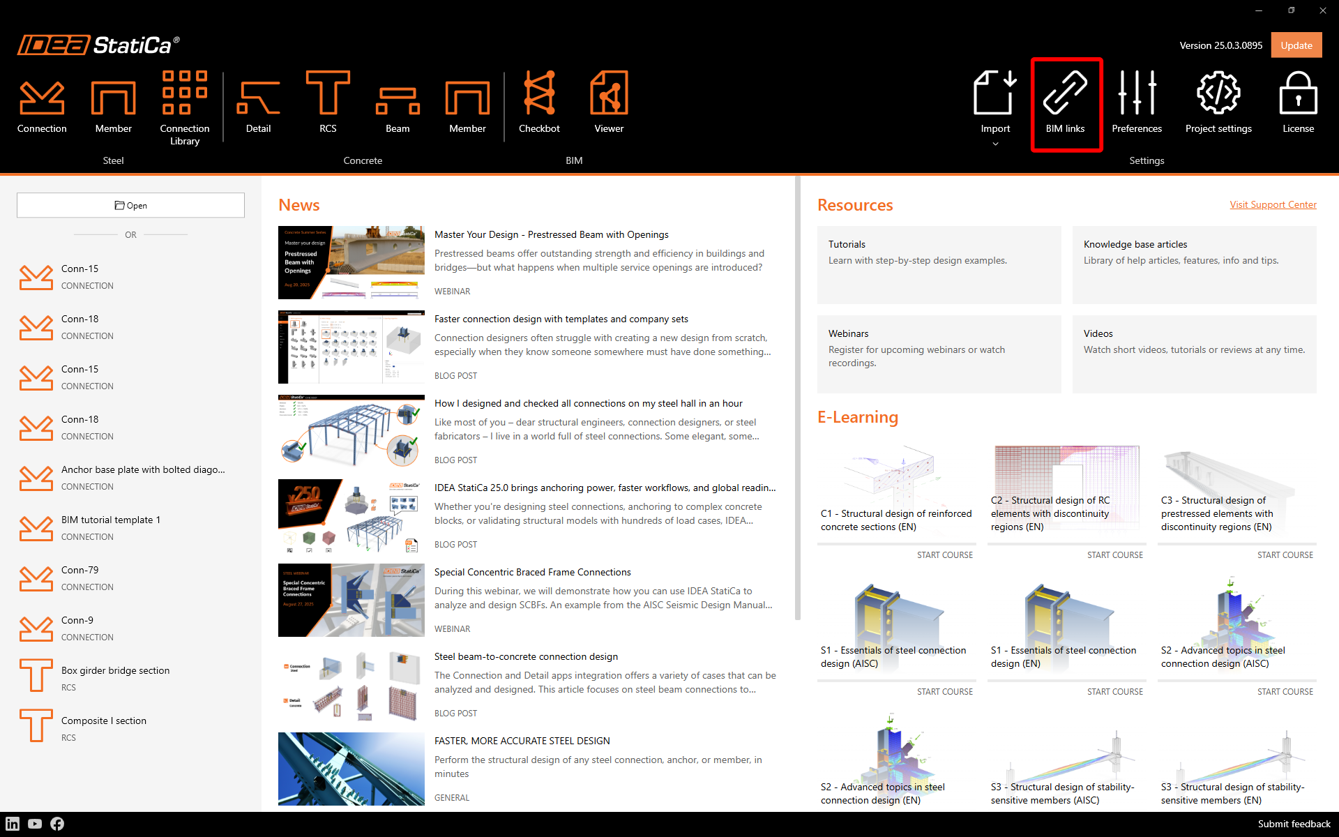
Öffnen Sie IDEA StatiCa und navigieren Sie zum Bereich BIM und öffnen Sie den BIM Link Installer. Eventuell erscheint eine Meldung Als Administrator ausführen, bitte bestätigen Sie mit Ja.
Bitte beachten Sie, dass einige FEA-Lösungen zusätzliche Schritte erfordern, um ihre BIM-Verbindung zu IDEA StatiCa vollständig zu aktivieren.
Öffnen Sie IDEA StatiCa und navigieren Sie zum Tab BIM und öffnen Sie den BIM-Link-Installer (Aktivieren deinen BIM-Link...).
Eine Benachrichtigung "Möchten Sie zulassen, dass diese Anwendung Änderungen an Ihrem Gerät vornimmt?" erscheinen, wenn ja, bestätigen Sie dies bitte mit Ja.
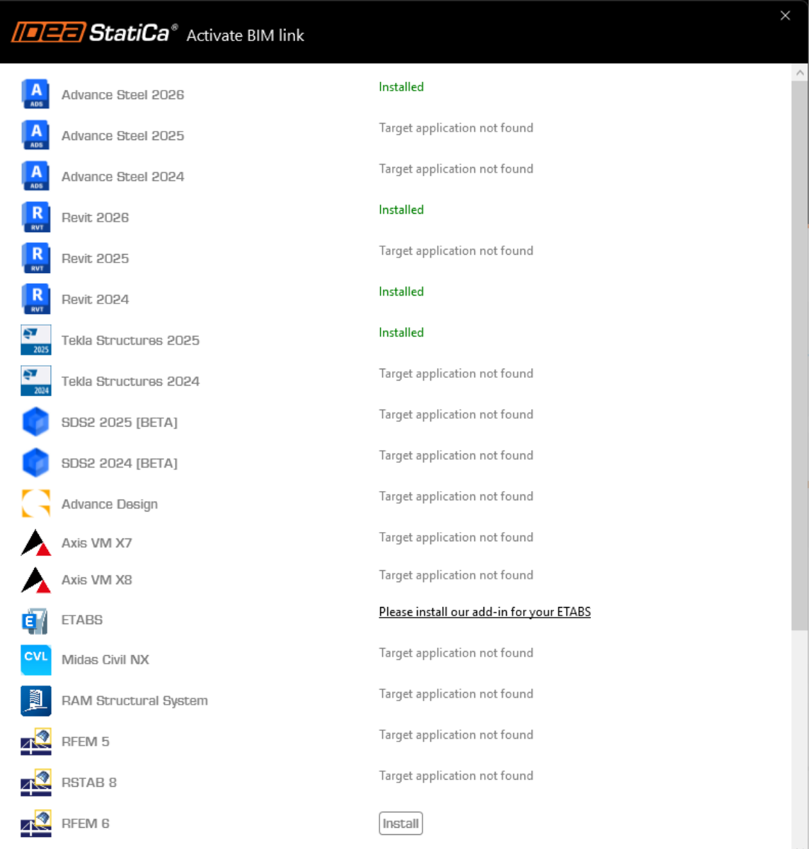
Der BIM-Link für die ausgewählte Software (falls gefunden) wird installiert. Der Bildschirm informiert Sie auch über den Status anderer BIM-Links, die möglicherweise bereits installiert wurden.
Verwendung der Verknüpfung
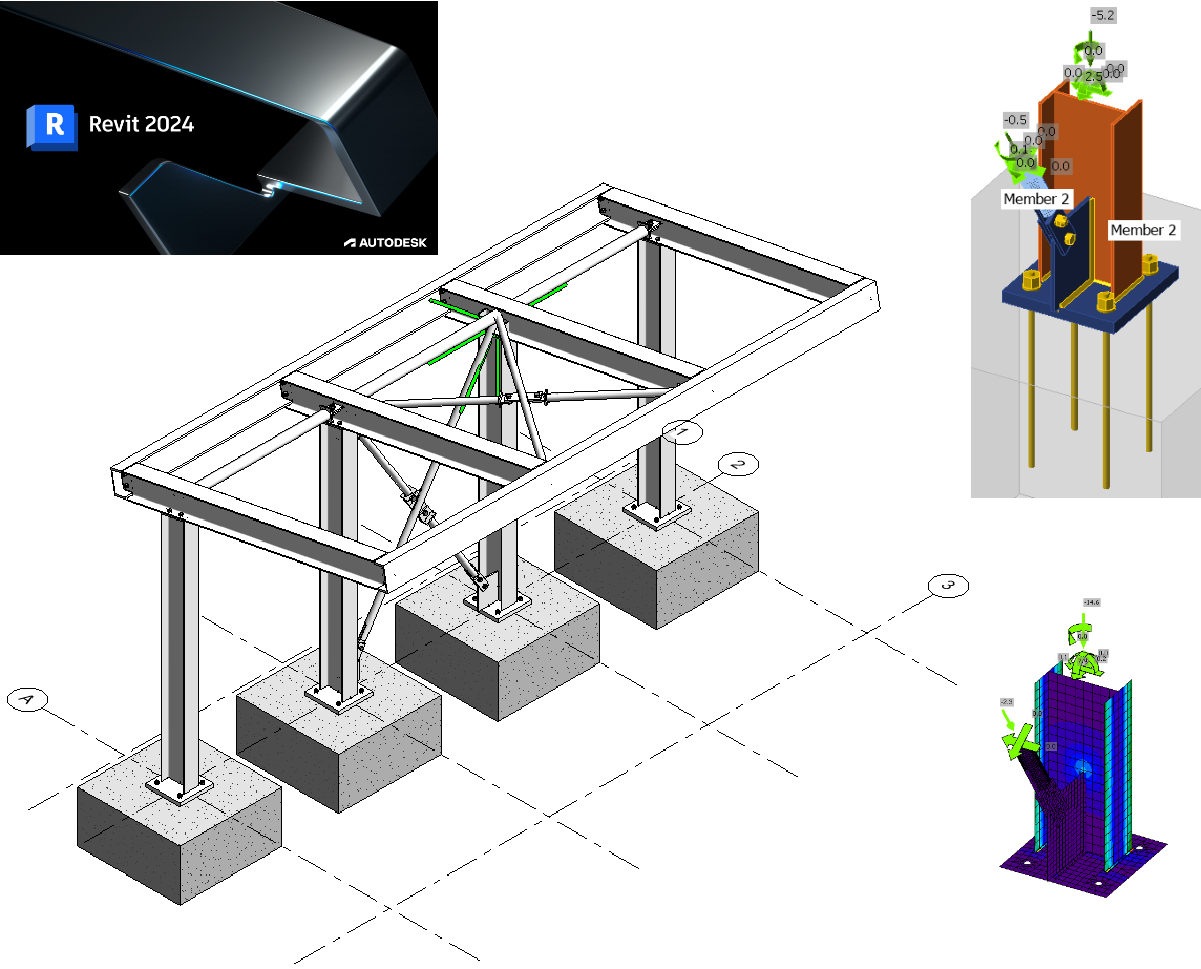
Autodesk Revit (Revit) verfügt über eine Funktion, die in anderen BIM-Anwendungen derzeit nicht zu finden ist: Es kann auch Ergebnisse aus einer geeigneten Finite-Elemente-Analyse-Lösung aufnehmen. Zu diesem Zweck haben wir ein solches Modell erstellt, das Sie mit diesem Tutorial unter Revit 2024 verwenden können. Die Ergebnisse wurden mit Robot Structural Analysis 2024 ermittelt. Seit Revit 2023 wurde ein neuer Ansatz zur analytischen Modellierung eingeführt, der einen Wechsel von der Automatisierung hin zu einem stärker ingenieurorientierten Ansatz bedeutet.
Öffnen Sie das Modell in Revit – Hinweis: Dieses Tutorial erfordert Version 2024 oder höher.
Es wurden zwei analytische 3D-Ansichten erstellt, um die Lasten und Ergebnisse zu überprüfen.
Hier sind die definierten Lasten (teilweise in Revit und mehr in Robot):

Die Normkombinationen wurden in Robot definiert, da dies dort wesentlich einfacher ist – und man könnte argumentieren, dass dies der richtige Ort dafür ist. Eine weitere Beobachtung ist, dass das Modell in Revit bis zu diesem Punkt weitgehend norm- und länderneutral ist – da die Lasten auf jeden nationalen Anhang angewendet werden könnten, um eine „lokale" Lösung zu erzeugen.
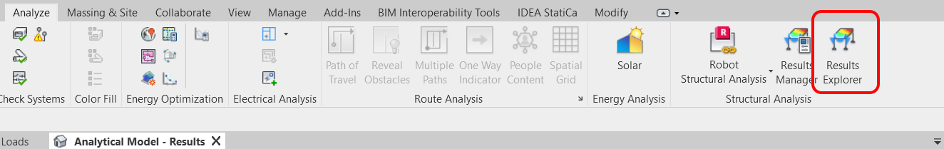
Obwohl die Ansicht „gesperrt" ist, müssen die Ergebnisse noch geladen werden. Gehen Sie dazu zur Registerkarte „Analysieren" und wählen Sie „Ergebnis-Explorer".
Wählen Sie im nächsten Fenster eine geeignete GZT-Lastkombination, z. B. My, und klicken Sie abschließend auf „Übernehmen".

Wenn Sie die Ansicht erweitern (denken Sie daran, sie zuerst zu entsperren), sehen Sie auch die Legende. Die Textgröße wird durch den allgemeinen Ansichtsmaßstab beeinflusst und kann entsprechend angepasst werden.
Die Ergebnisse zeigen die My-Werte für eine GZT-Lastkombination, die in Robot definiert wurde.

Verschiedene Ergebnisse können mithilfe der Ergebnis-Explorer-Funktion auf der Registerkarte „Analysieren" visualisiert werden.
Kehren Sie zur 3D-Stahlbauansicht zurück. Die dargestellten Stahlanschlüsse wurden in Revit modelliert. Sie sind nur sichtbar, wenn der Detailgrad auf Fein eingestellt ist.
Die BIM-Verknüpfung sollte automatisch integriert sein. Sie finden sie im oberen Menüband unter IDEA StatiCa -> Checkbot. Dadurch wird die Checkbot-Anwendung geöffnet.

Wählen Sie die Option Neu mit dem Projekttyp Stahl und dem Bemessungscode EN. Wählen Sie dann Projekt erstellen.
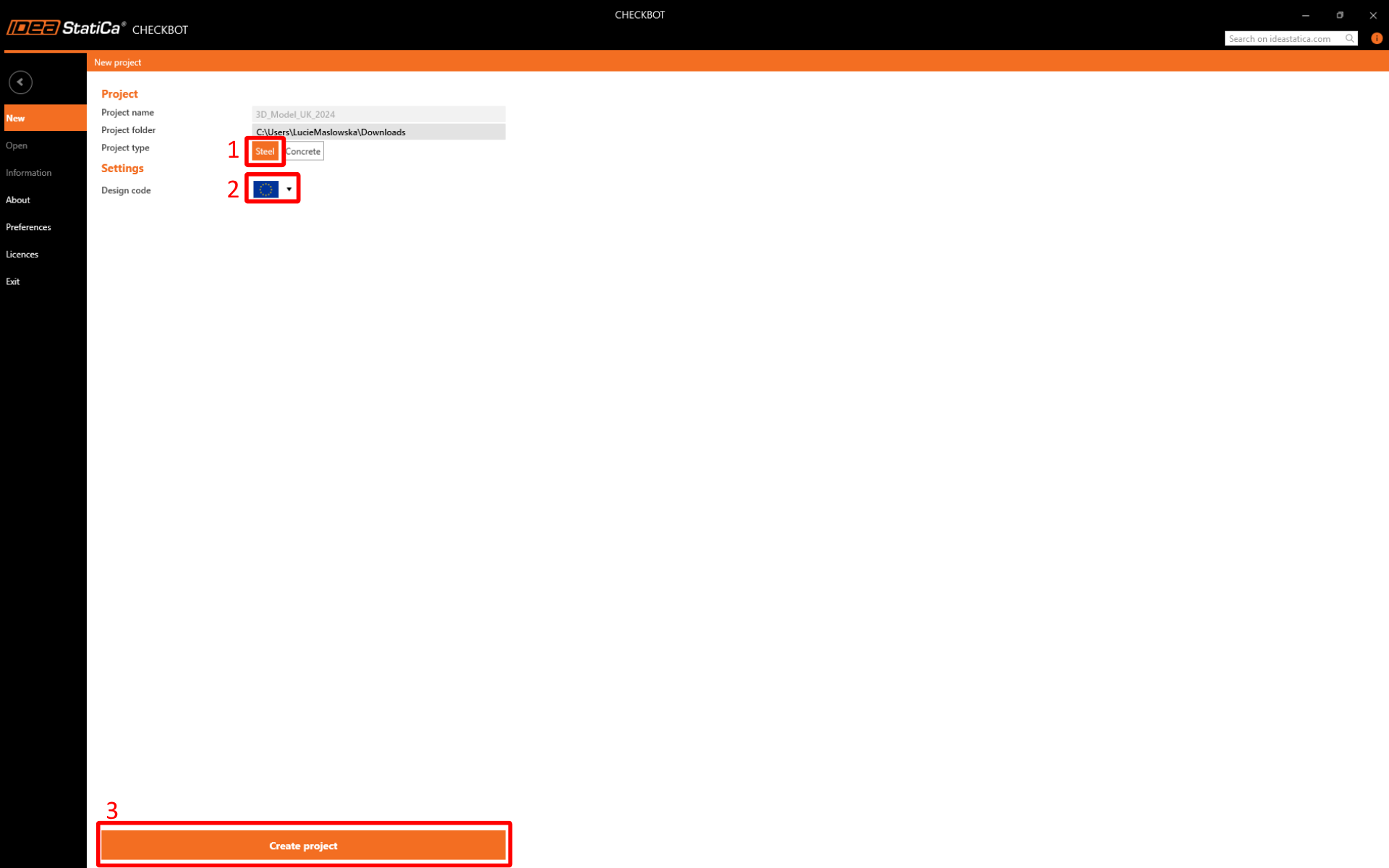
Das neue Checkbot-Projekt ist bereit, Verbindungen aus Autodesk Revit zu importieren.

Wir werden die Fußplatte und die Aussteifungsverbindung am Fuß einer der Innenstützen untersuchen.

Diese Verbindung besteht eigentlich aus zwei Verbindungen. Eine für die Fußplatte und eine für die Aussteifung. Die Ausnahme ist jedoch, dass die Fußplattenverbindung in ihre Einzelteile aufgelöst (explodiert) wurde. Dies ist auf aktuelle Einschränkungen der Verbindungsinteraktion zurückzuführen.
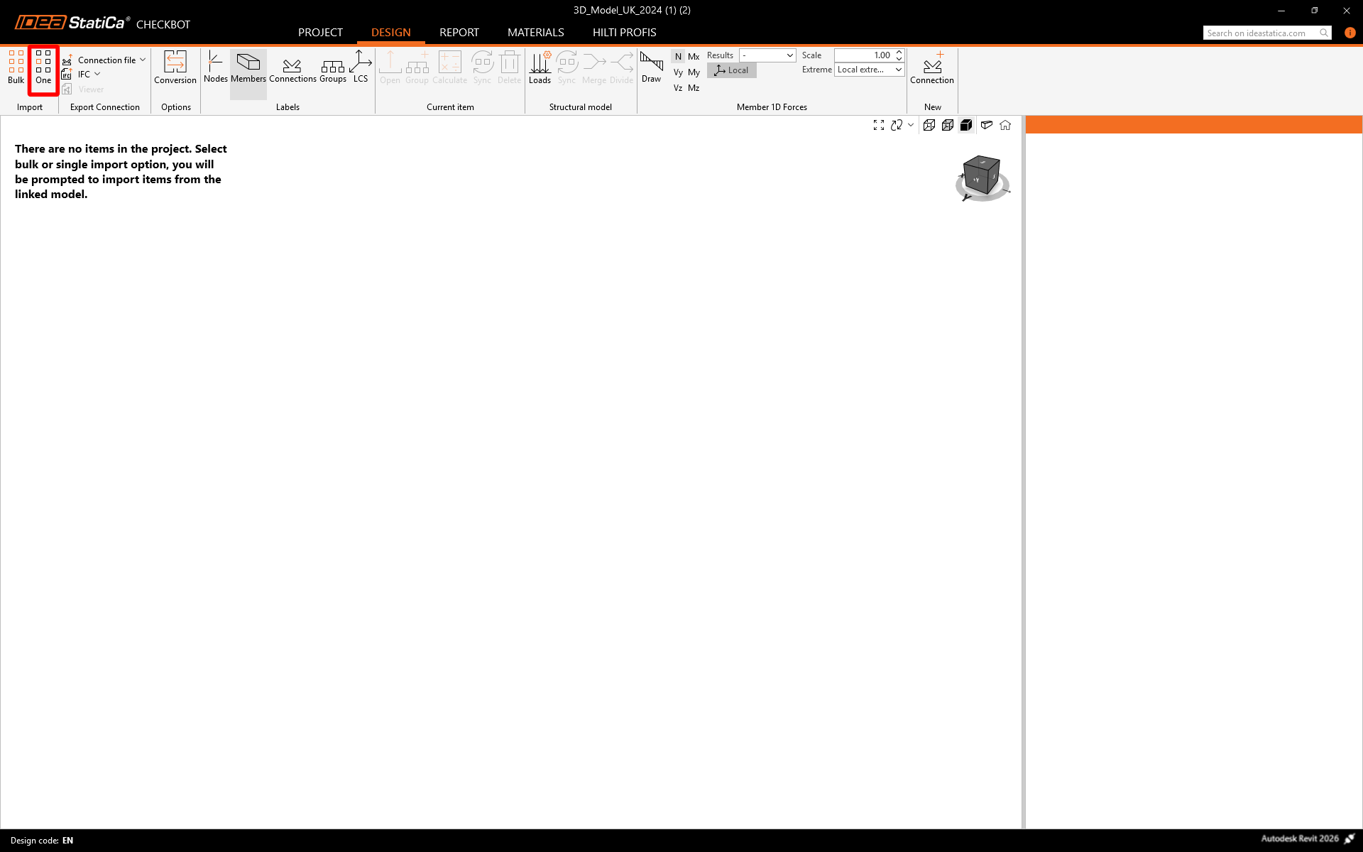
Wählen Sie in Checkbot im Importbereich Einzeln.
Der Fokus wechselt zurück zu Revit und Sie werden aufgefordert, eine Verbindung auszuwählen – wählen Sie die Aussteifungsverbindung.

Anschließend werden Sie aufgefordert, Verbindungsobjekte auszuwählen (das sind die Bauteile und anderen Elemente, aus denen die gesamte Verbindung besteht) – wählen Sie die Objekte mit einem Kreuzfenster wie dargestellt aus.

Wählen Sie abschließend „Fertig stellen" oben rechts im Menübandbereich von Revit.

Die Bauteile und der Verbindungsplatzhalter werden dann in Checkbot importiert.
Weitere Informationen zur Checkbot-Oberfläche finden Sie in unseren Tutorials zu Checkbot und anderen BIM-Verknüpfungen.
Geometrie
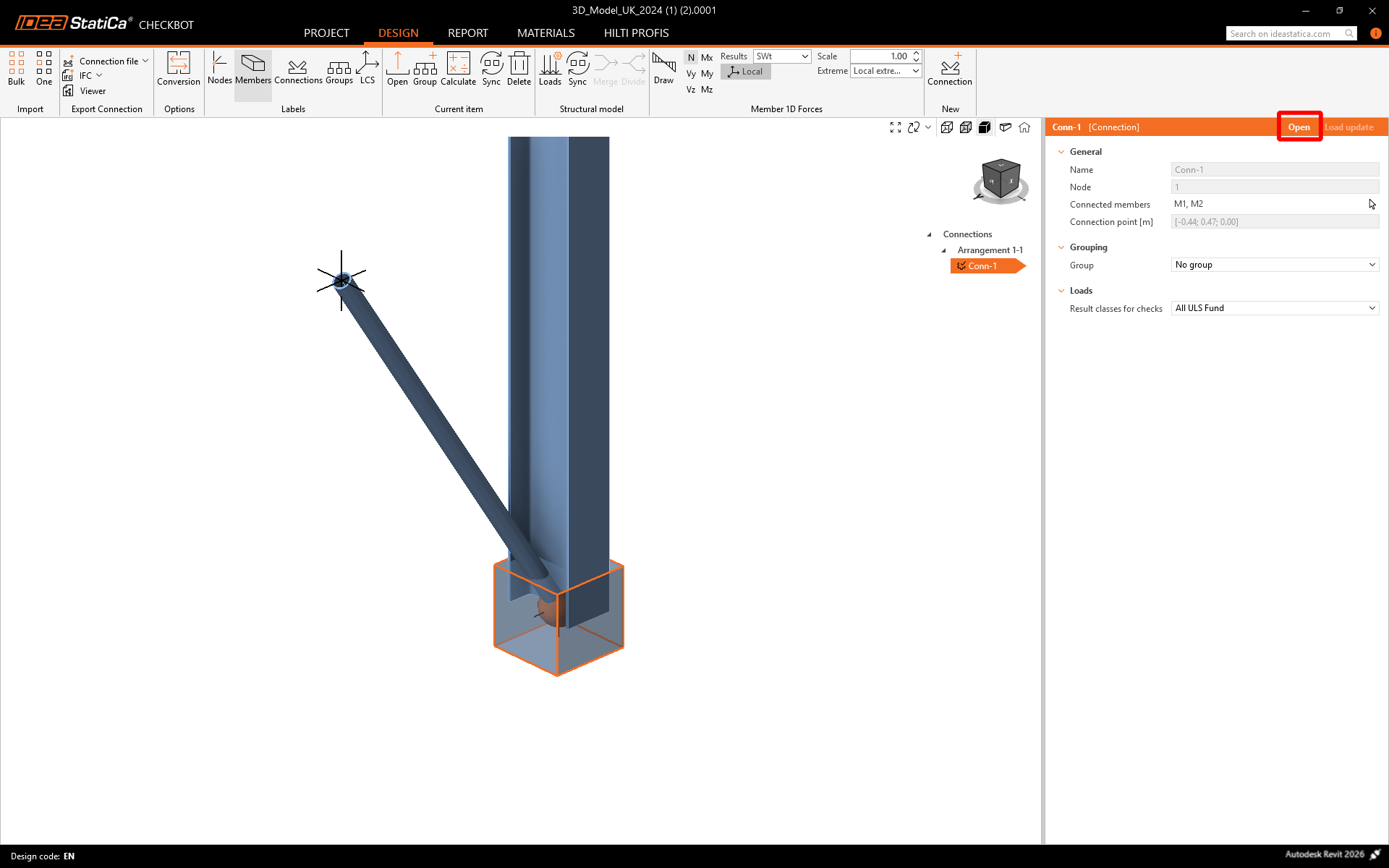
Wählen Sie in Checkbot entweder „Öffnen" im rechten Bereich
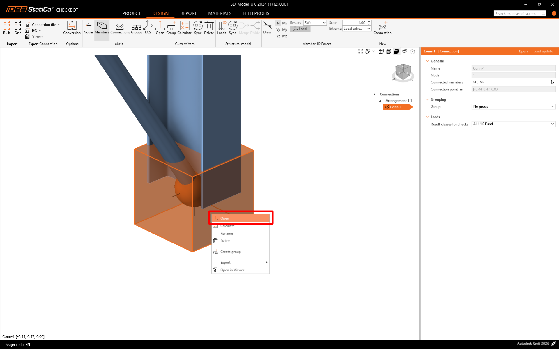
oder klicken Sie mit der rechten Maustaste auf das Verbindungsfeld oder den Verbindungseintrag und wählen Sie „Öffnen".
Wenn alles wie gezeigt ausgewählt wurde, sollte die Ansicht wie folgt aussehen:
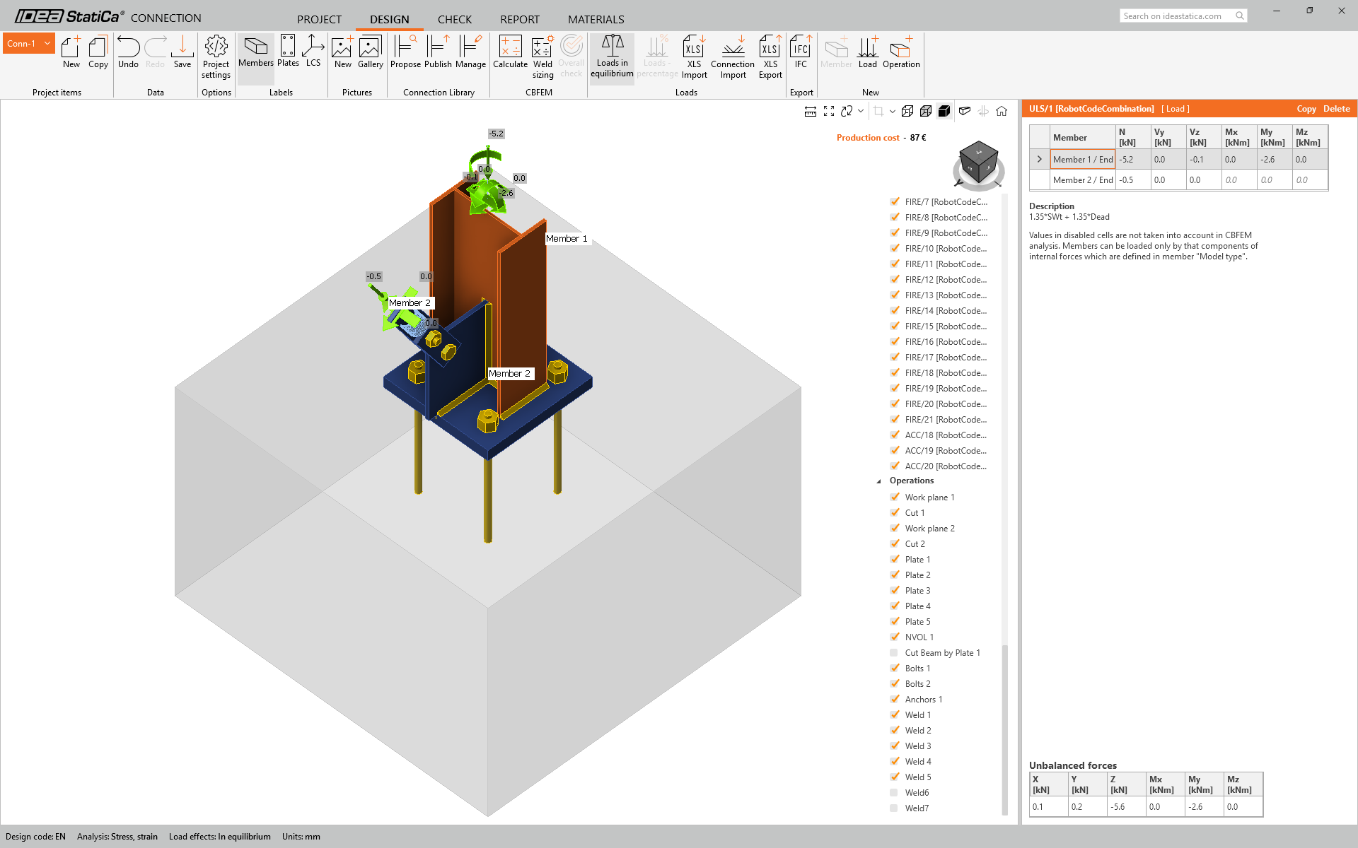
Hier ist der kombinierte geometrische und analytische Ansatz ideal, da er eine sofort verwendbare Verbindung in IDEA StatiCa erzeugt. Bei früheren Tutorials, die entweder auf FEA- oder BIM-Lösungen basieren, fehlt immer ein Teil.
Wir müssen jedoch noch einige Bearbeitungen vornehmen, bevor wir berechnen können. Obwohl die Aussteifung modelliert ist, müssen wir noch den richtigen Modelltyp zuweisen – N-Vy-Vz. Dies liegt daran, dass eine einzelne Schraube verwendet wird.
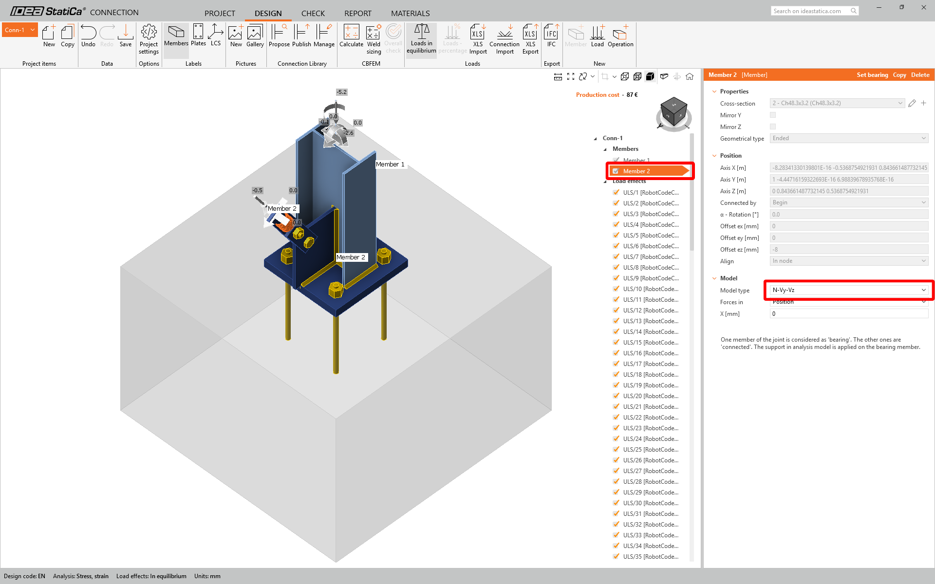
Die Verbindung wird in ihrem aktuellen Zustand dennoch einen Mechanismus erzeugen, da eine einzelne Schraube durch die Sandwichplatten und das Fahnenblech verläuft. Um dies zu umgehen, können wir entweder weitere Schrauben einführen (was die Verbindung größer und kostspieliger macht) oder eine kleine Schweißnaht an der hinteren Kante verwenden.
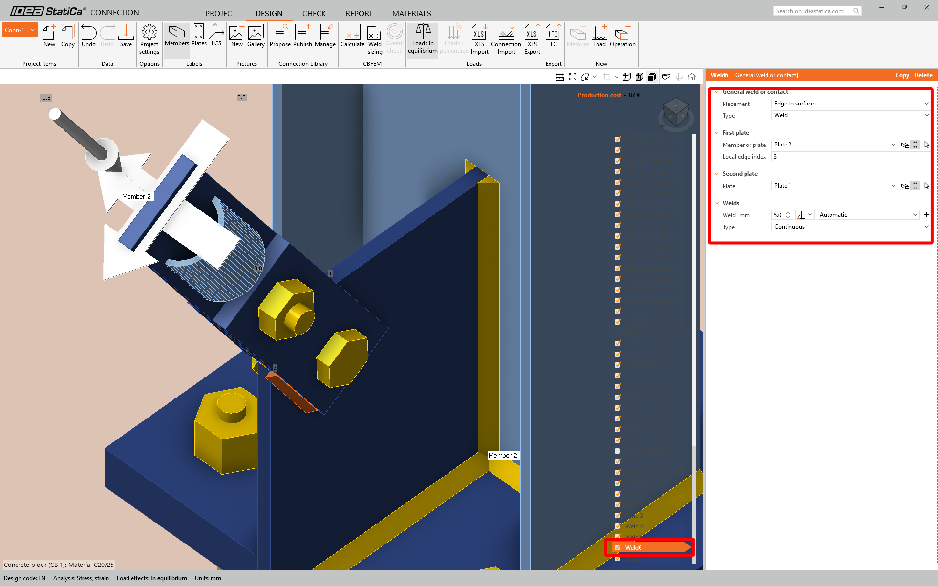
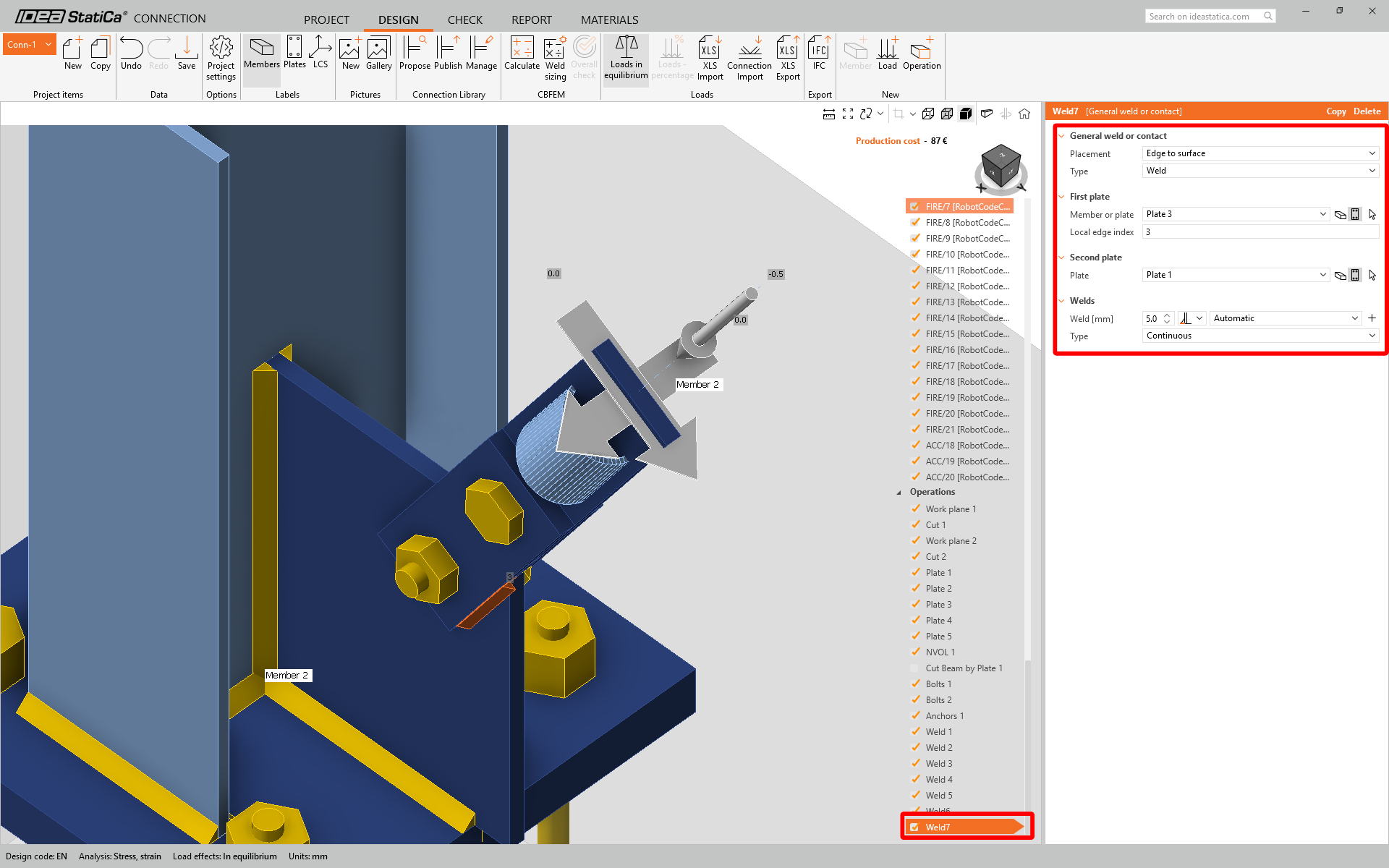
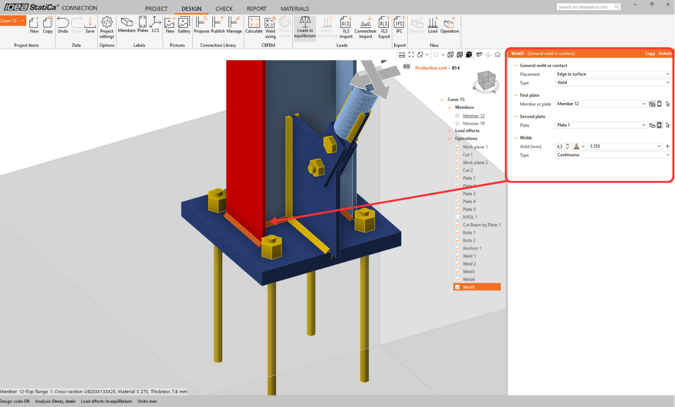
Fügen Sie an jeder Sandwichplatte eine Schweißnaht an der Unterkante hinzu, wo sie das Fahnenblech berührt:
Hinweis: Bitte beachten Sie, dass die Bauteilnummern nicht immer gleich erscheinen. Daher ist es bei der folgenden Vorgehensweise immer besser, die Platte über die „Auswahl"-Funktion (kleiner Pfeil neben dem Namen des Bauteils/der Platte) auszuwählen. Dies gilt auch für Platten, um sicherzustellen, dass die richtigen Komponenten verbunden werden.
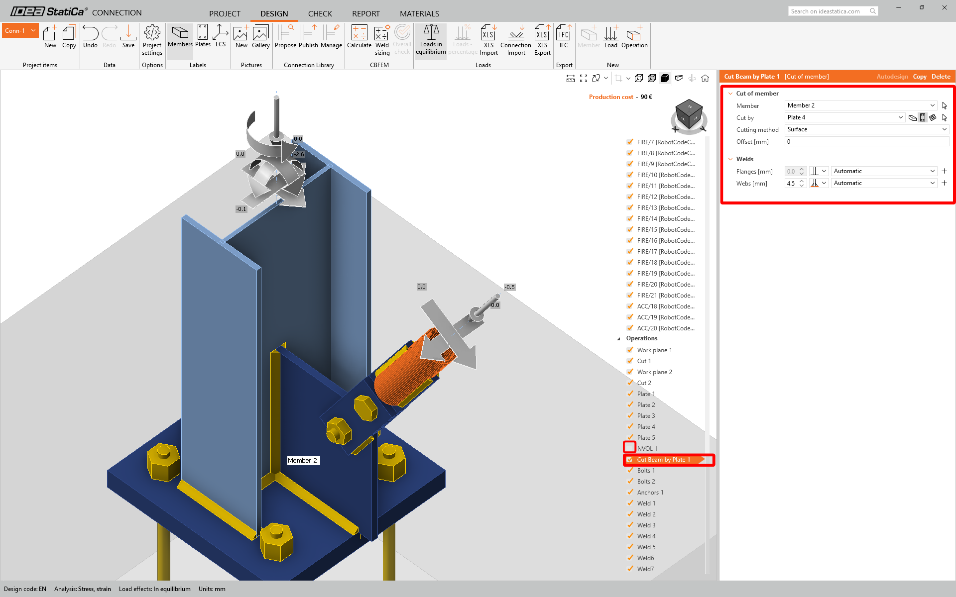
- Die rohrförmige Aussteifung wird durch ein negatives Volumen geschnitten und schließlich geschweißt. Es gibt jedoch eine bessere Methode, die bessere Ergebnisse liefert: die Aussteifung durch die Platte schneiden und beide automatisch miteinander verschweißen. Deaktivieren Sie NVOL 1; passen Sie „Bauteil durch Bauteil schneiden 1" wie folgt an.
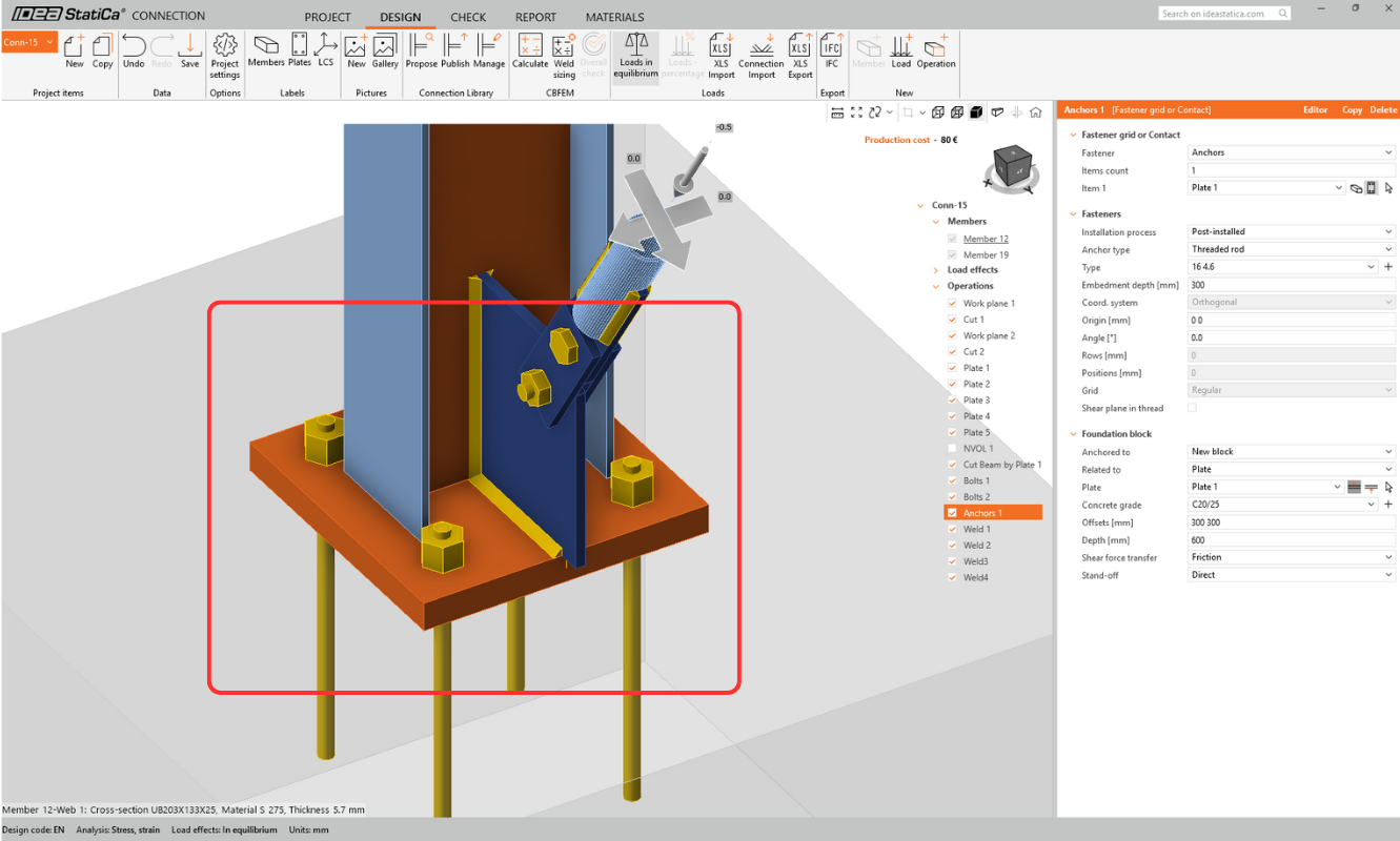
- Sie können auch feststellen, dass das Element nicht mit der Fußplatte verbunden ist und die Schweißnaht manuell hinzugefügt werden muss.
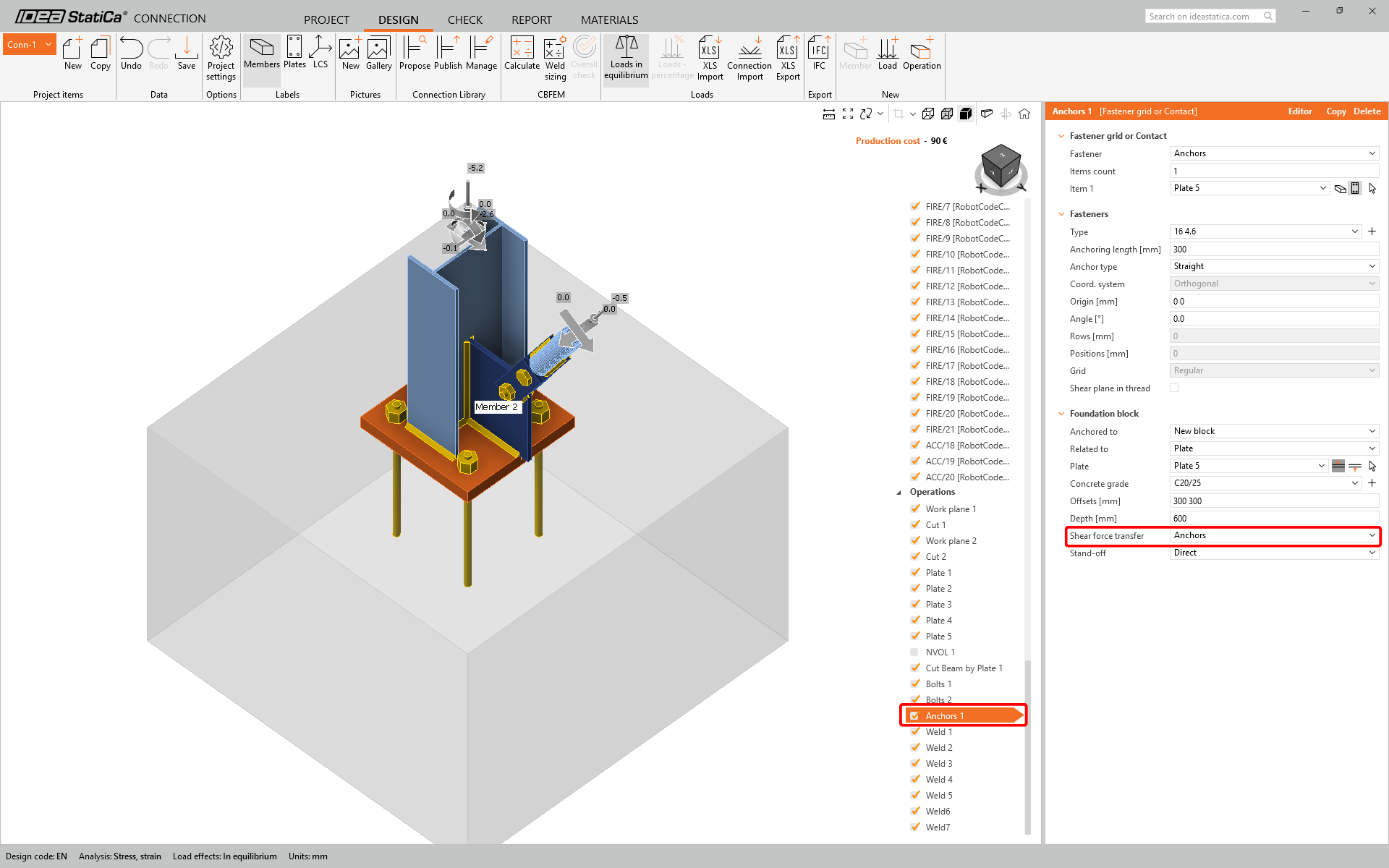
- Bearbeiten Sie die Anker-Operation so, dass die Querkraft von den Ankern und nicht durch Reibung aufgenommen wird.
Da das IDEA-Verbindungsmodell aus dem Revit-Modell stammt, könnte man argumentieren, dass die Quellinformationen zuerst korrigiert und dann mit IDEA synchronisiert werden sollten (um die „Single Source of Truth" als solche zu erhalten).
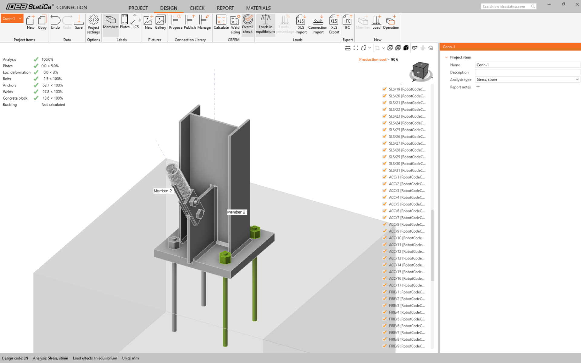
Das Modell ist nun berechnungsbereit. Drücken Sie im oberen Menüband auf „Berechnen". Nach wenigen Augenblicken erscheinen die ersten „Ampel"-Ergebnisse.
Abschließend möchten wir noch auf die Verwendung einer generischen Verbindung in Revit hinweisen. Eine generische Verbindung wird als Platzhalter verwendet – „Hier befindet sich eine Verbindung, aber ich weiß nicht, wie sie aussieht" oder die tatsächliche Verbindung ist für Revit zu komplex!
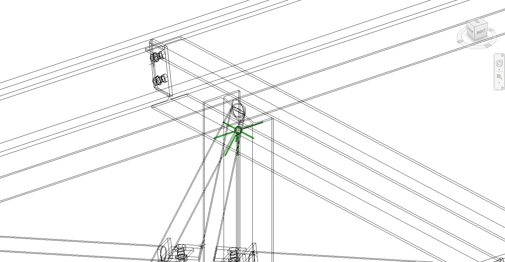
Wenn Sie in den Drahtgittermodus wechseln, sehen Sie deutlich einen grünen Verbindungshalter auf einer Stütze, in die mehrere Träger ein- und auslaufen. Mit einem ähnlichen Arbeitsablauf wie beim Fußplatten- und Aussteifungsbeispiel kann diese Verbindung in Checkbot importiert und mit den Operationen in IDEA StatiCa bearbeitet werden. Der Vorteil dieses Arbeitsablaufs ist nicht so groß wie beim vorherigen Beispiel, aber es ist eine Möglichkeit, die Bauteile und ihre Ergebnisse zu importieren.

Es wird Situationen geben, in denen Änderungen am Revit-Modell erforderlich sind. Der bevorzugte Arbeitsablauf wäre, die gewünschten geometrischen Änderungen in Revit vorzunehmen, das Modell zur Analyse zu senden, diese Änderungen zu analysieren und zu bemessen, bevor etwaige Unterschiede zurückgesendet werden. Checkbot kann dann nach diesen Änderungen suchen.
Modell synchronisieren
Manchmal gibt es Änderungen an Ihrem FEA/BIM-Modell, wie z. B. andere Querschnittsgrößen von Bauteilen oder Lasten. Diese können zwischen Checkbot und dem FEA/BIM-Modell synchronisiert werden.
Es gibt zwei mögliche Alternativen:
- Das aktuelle Element synchronisieren (wenn ein oder mehrere Knoten ausgewählt sind)
- Das gesamte importierte Tragwerksmodell synchronisieren
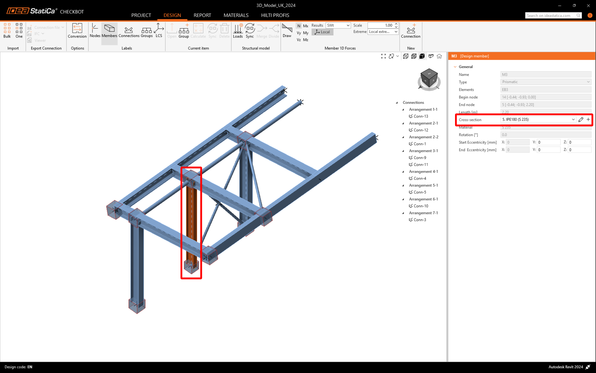
Um diese Funktion zu testen, können Sie eine Querschnittsgröße oder -form eines Bauteils in Ihrer BIM-Anwendung ändern oder einen Lastfall bzw. eine Lastkombination usw. anpassen: Ändern Sie die ausgewählte Stütze auf einen kleineren Querschnitt.
Wählen Sie in Checkbot die bemessenen Verbindungen aus (es können mehrere sein) und wählen Sie im Bereich „Aktuelles Element" die Option Sync.

Das Checkbot-Projekt wird aktualisiert, die Verbindungsbemessung bleibt erhalten, aber die Ergebnisse werden ungültig. Sie können sehen, dass die Stütze nun aktualisiert wurde – entsprechend der Änderung im BIM-Modell.
Führen Sie den Normnachweis für die markierten Verbindungen erneut durch, indem Sie im Bereich „Aktuelles Element" Berechnen auswählen. Bitte beachten Sie, dass größere Änderungen im Modell möglicherweise zusätzliche Validierungsschritte für die betroffenen Verbindungen erfordern (wie oben beschrieben).

Wenn die Verbindungen nicht die gewünschten Ergebnisse liefern, können Sie diese erneut öffnen, um das Design zu optimieren (d. h. zu verstärken, wenn sie den Normnachweis nicht bestehen, oder zu erleichtern, wenn die Ausnutzung zu gering ist).
Sie haben Autodesk Revit erfolgreich über Checkbot mit IDEA StatiCa Connection verknüpft. Sie haben sogar Funktionen erkundet, die es ermöglichen, den Revit-Arbeitsablauf über bekannte, veröffentlichte Verbindungstypen hinaus zu erweitern.