
Space Gass BIM link for the structural design of a steel connection (AS)
Hoe activeer je de link.
- Download en installeer de laatste versie van IDEA StatiCa
- Zorg ervoor dat u een ondersteunde versie van uw FEA/BIM-oplossing gebruikt.
IDEA StatiCa integreert BIM-links in uw FEA/BIM-oplossingen tijdens de installatie ervan. U kunt de status controleren en meer BIM links activeren voor software die na de installering in de BIM link installer is opgenomen.
Houd er rekening mee dat sommige FEA-oplossingen extra stappen vereisen om de BIM-link met IDEA StatiCa volledig te activeren.
Open IDEA StatiCa en navigeer naar de BIM tab en open de BIM link installer (Activate your BIM link...).
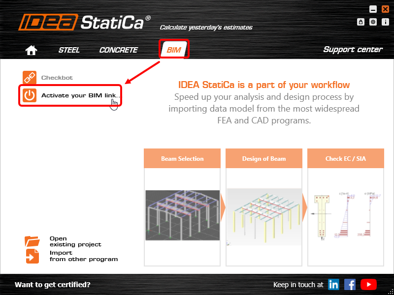
Er kan een melding verschijnen "Wilt u toestaan dat deze app wijzigingen aanbrengt aan uw apparaat?", zo ja, bevestig dan met de Ja-knop.
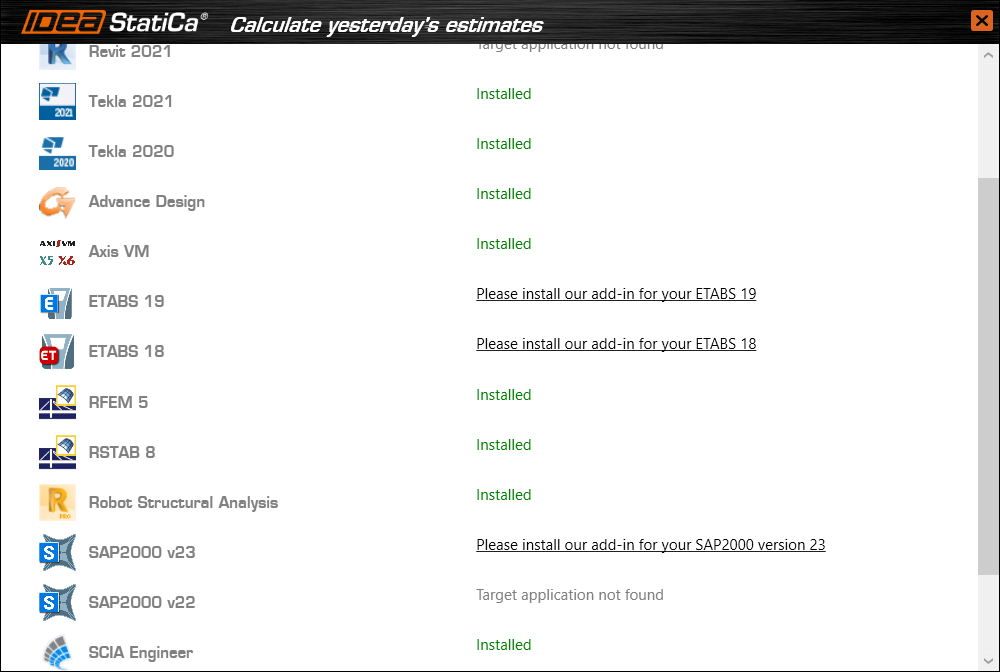
De BIM-link voor de geselecteerde software (indien gevonden) wordt geïnstalleerd. Het scherm toont ook de status van andere BIM-links die mogelijk al zijn geïnstalleerd.
How to use the link
Open the attached AS Project in Space Gass and run the calculation.
The BIM link should be automatically integrated. You can find it in the top ribbon under Design -> IDEA StatiCa Checkbot. This will open the Checkbot application.

Select the New option with project type Steel, AS design code. Then select Create project.

The new Checkbot project is ready to import connections from Space Gass.
Import
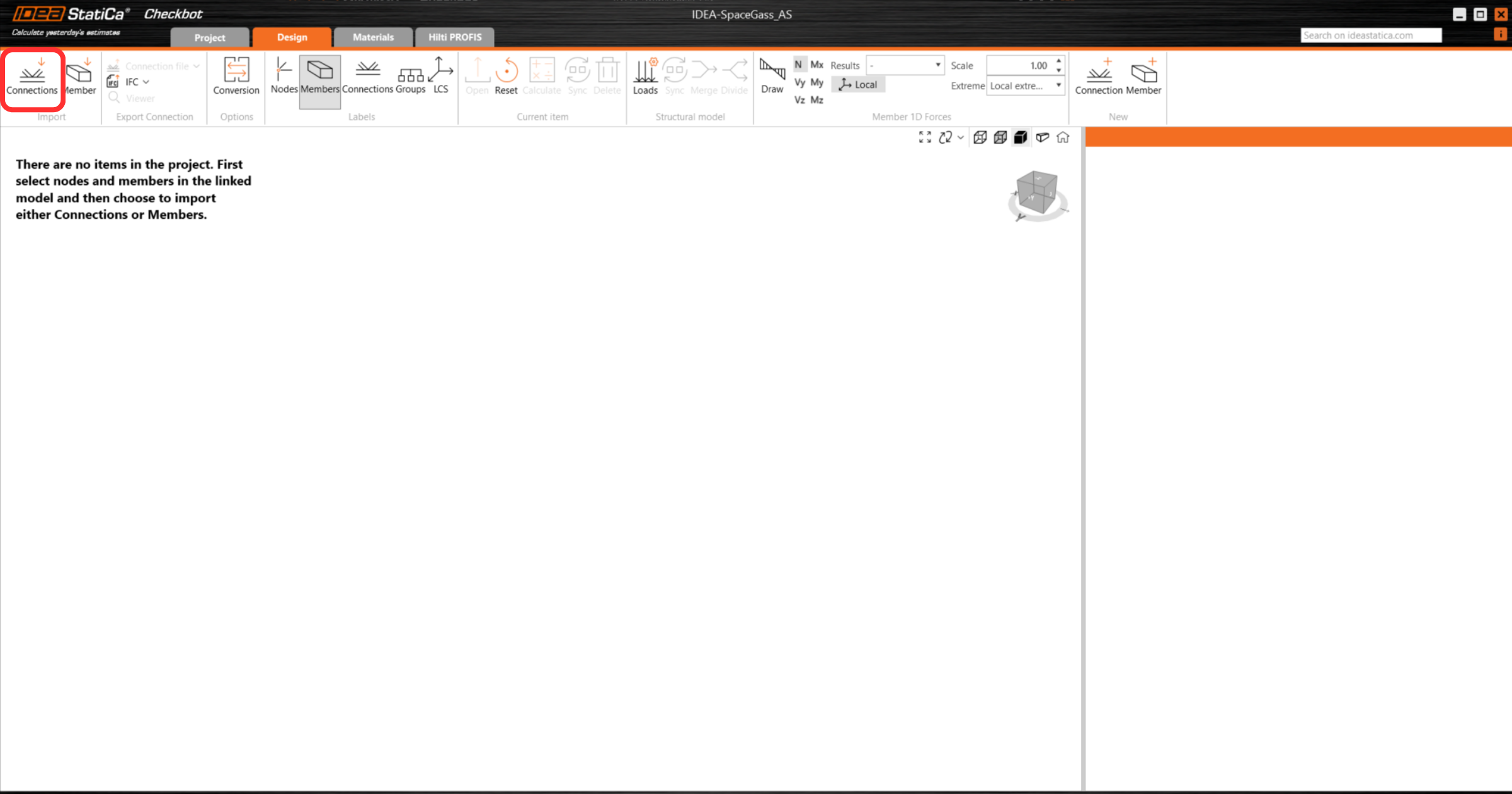
In Checkbot select Connections.
Then in Space Gass, select one of the inside columns lowest node, then right-click, select OK.
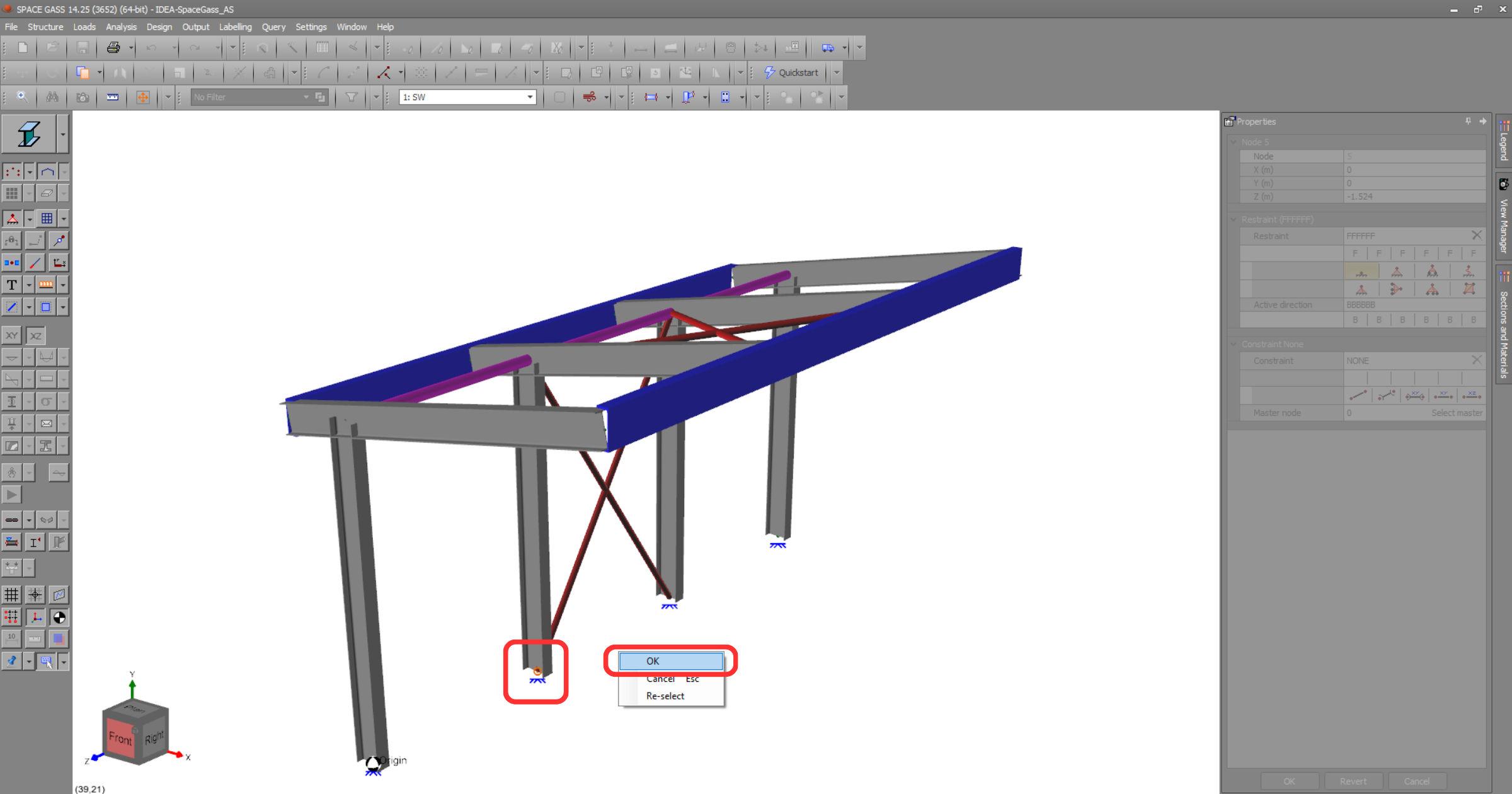
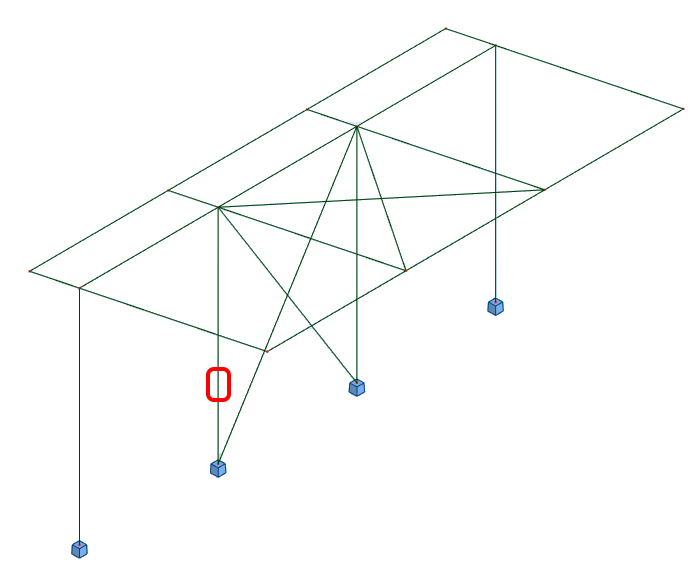
This will import the column and its load effects into Checkbot - with the same coordinates, orientations, and section sizes as per the FEA/BIM model.
Please note that your node and member numbering might be different.
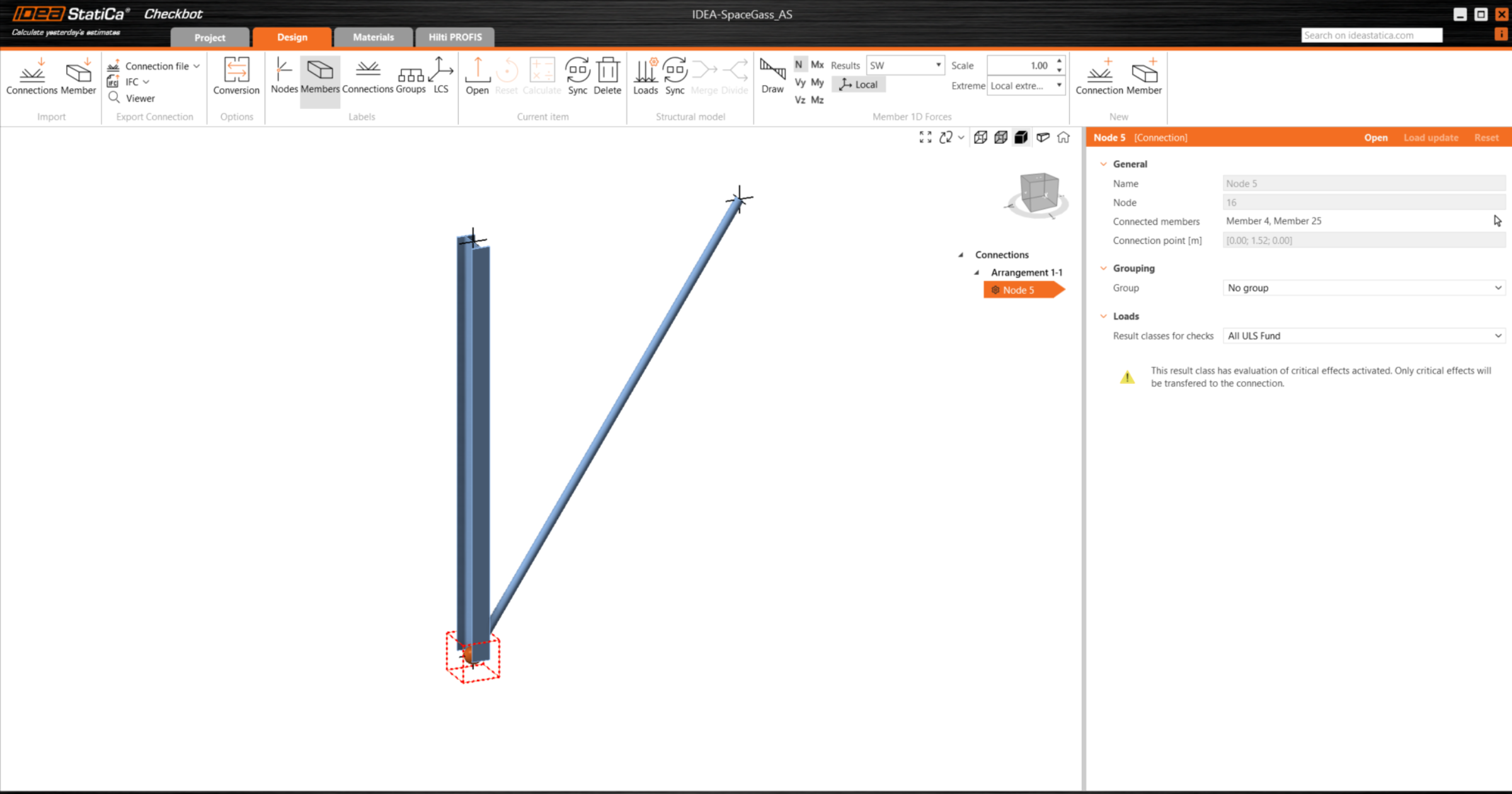
Please note the 3D workspace is designed to show an overview of the imported structure and not a detailed view of the actual connections.
For more information on Checkbot, see here.
For several FEA/BIM solutions, you can also import multiple connections into Checkbot in the same manner as above. Instead of selecting one node and the connected members, you can select several nodes and members using the selection methods within the application.
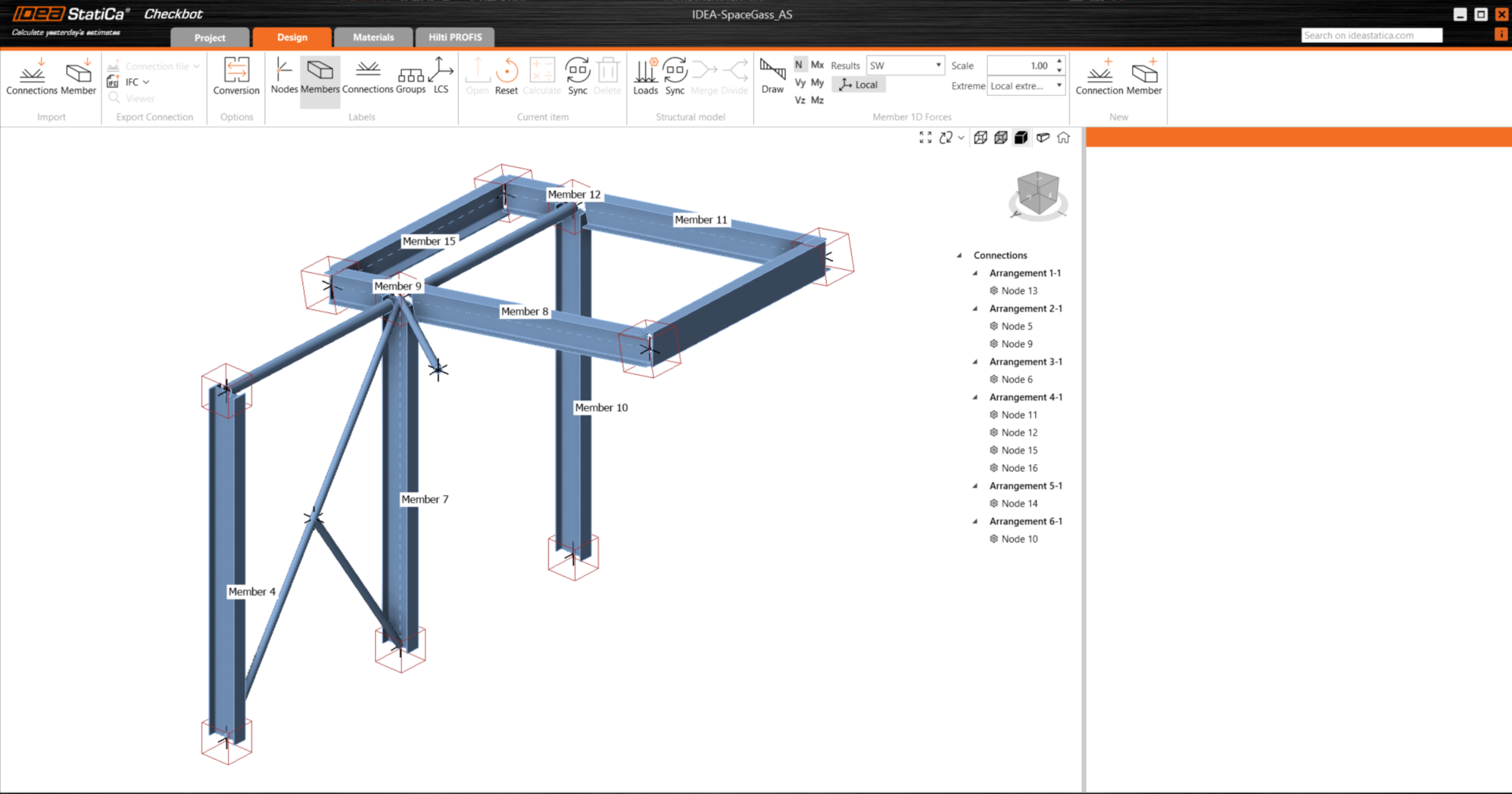
We recommend not importing all of the connections at the same time but building up the connections incrementally.
Geometry
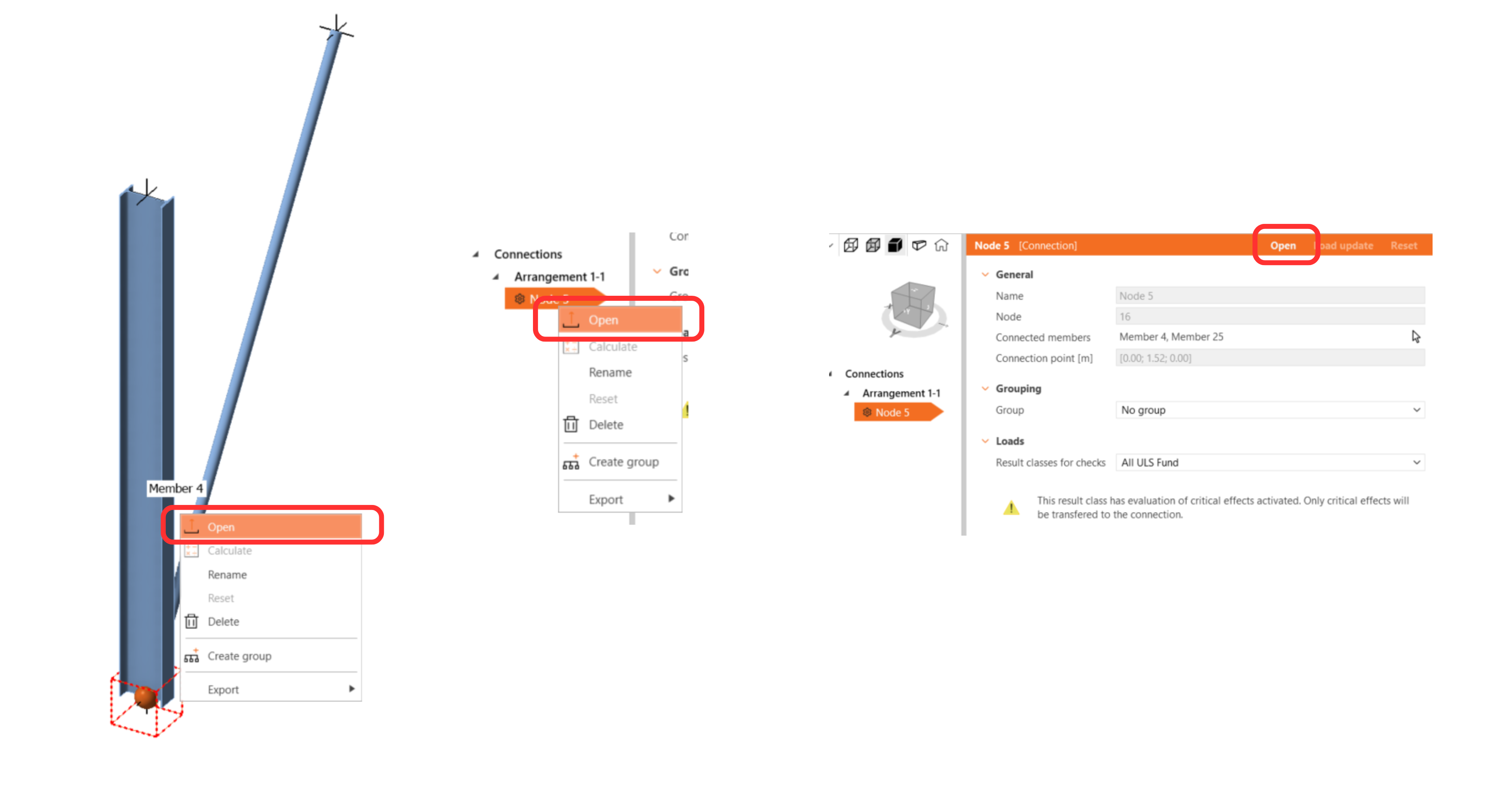
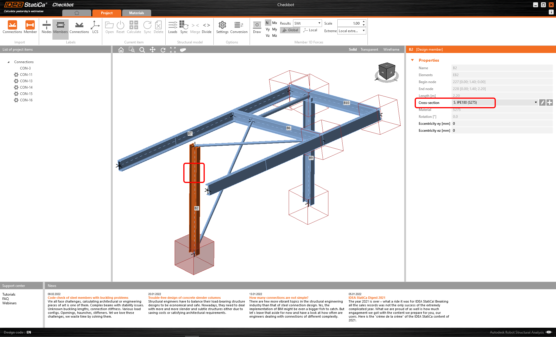
In the list of project items under Connections and with a connection highlighted in Checkbot you can either right-mouse click and select Open or click the ribbon command Open to start designing, code-checking, and reporting.
The settings of members are taken from the original FEA/BIM application. You can, however, change the section size of any member on the main Checkbot screen, but this will break the link with FEA/BIM application in this session unless it's synchronized again.
The imported connection is opened in the IDEA StatiCa Connection application.

You may see none or different Load effects from your preferred FEA/BIM* solution depending on how the load case combinations have been defined. By default, IDEA StatiCa will choose the most critical for code-checking purposes. (* Some BIM solutions are not able to store the load case combination results)
For more information on Load effects see here.
Design
We are going to be using a single bolt connection for the diagonal brace. For this type of connection, we must also change the Model type of the brace member to N-Vy-Vz. Select the brace in the list of Members and modify the Model type in the drop-down list.

We are going to use the Connection Library to generate a connection. Select Propose and IDEA StatiCa will put forward possible solutions for the current geometry.
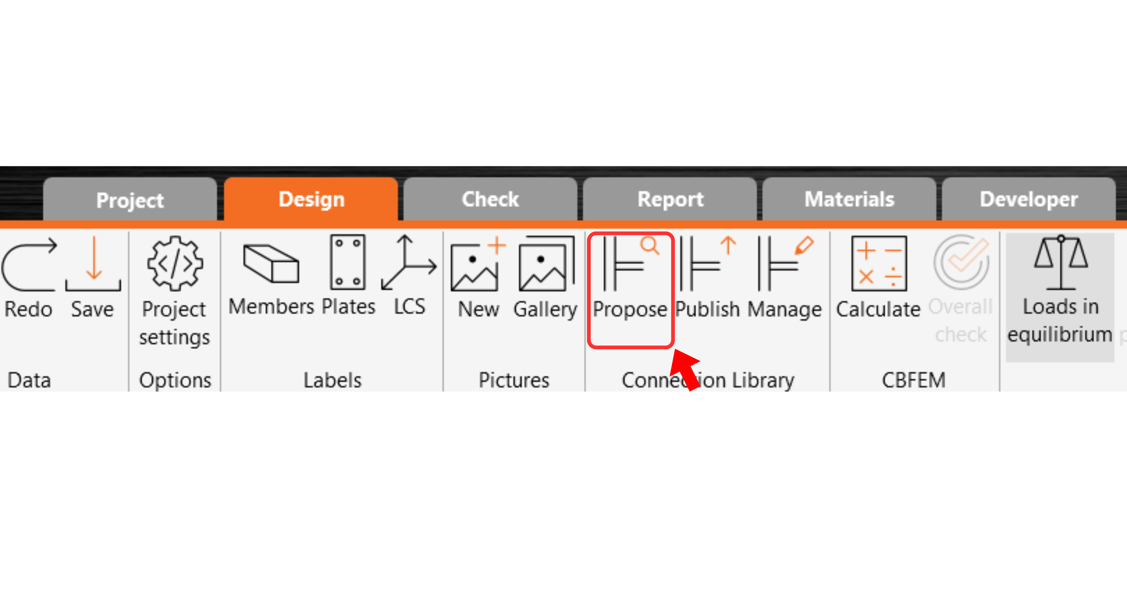
Connection Library shows you the possible solutions for the current geometry. Choose the template offered and press OK.

Accept the proposed values for the bolts and concrete block and press OK.

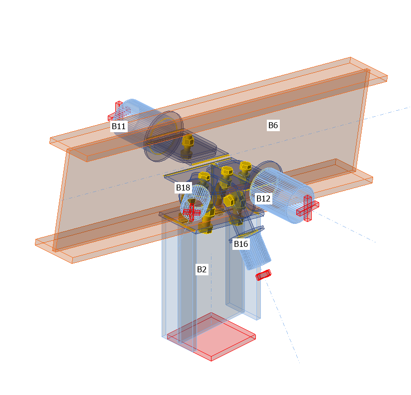
This is what the initial connection looks like.
With these default parameters for the Base plate.

These are the parameters for the Connecting plate.

That completes the design of the connection for the column base plate with a diagonal brace.
Code-check and Report
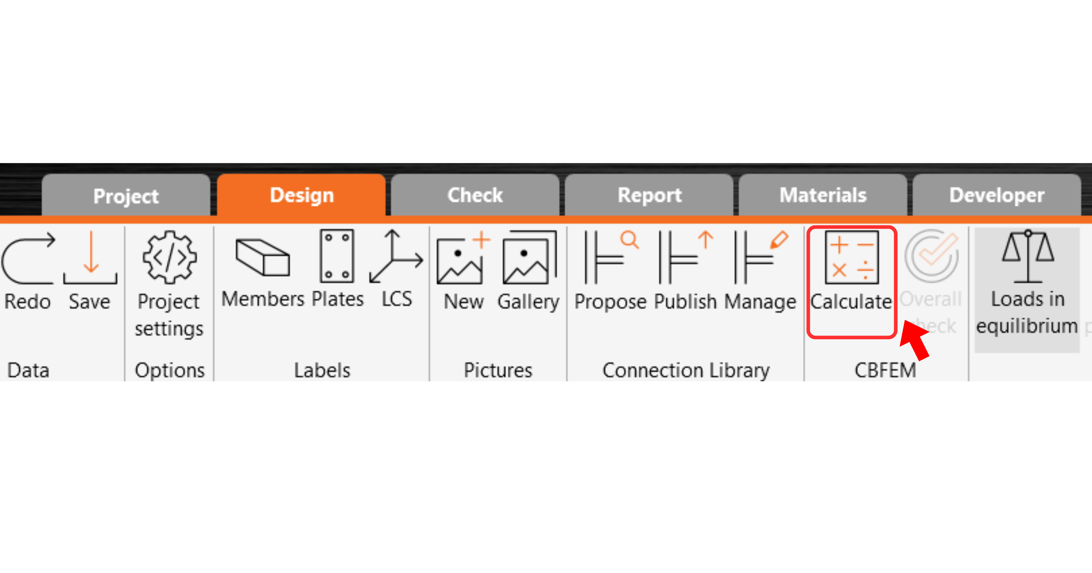
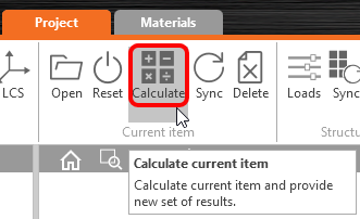
Now run a code-check using the Calculate icon in the CBFEM panel from the top ribbon.
Within IDEA StatiCa Connection, you can carry out many different types of analysis and code-checks. For more information, please see here.
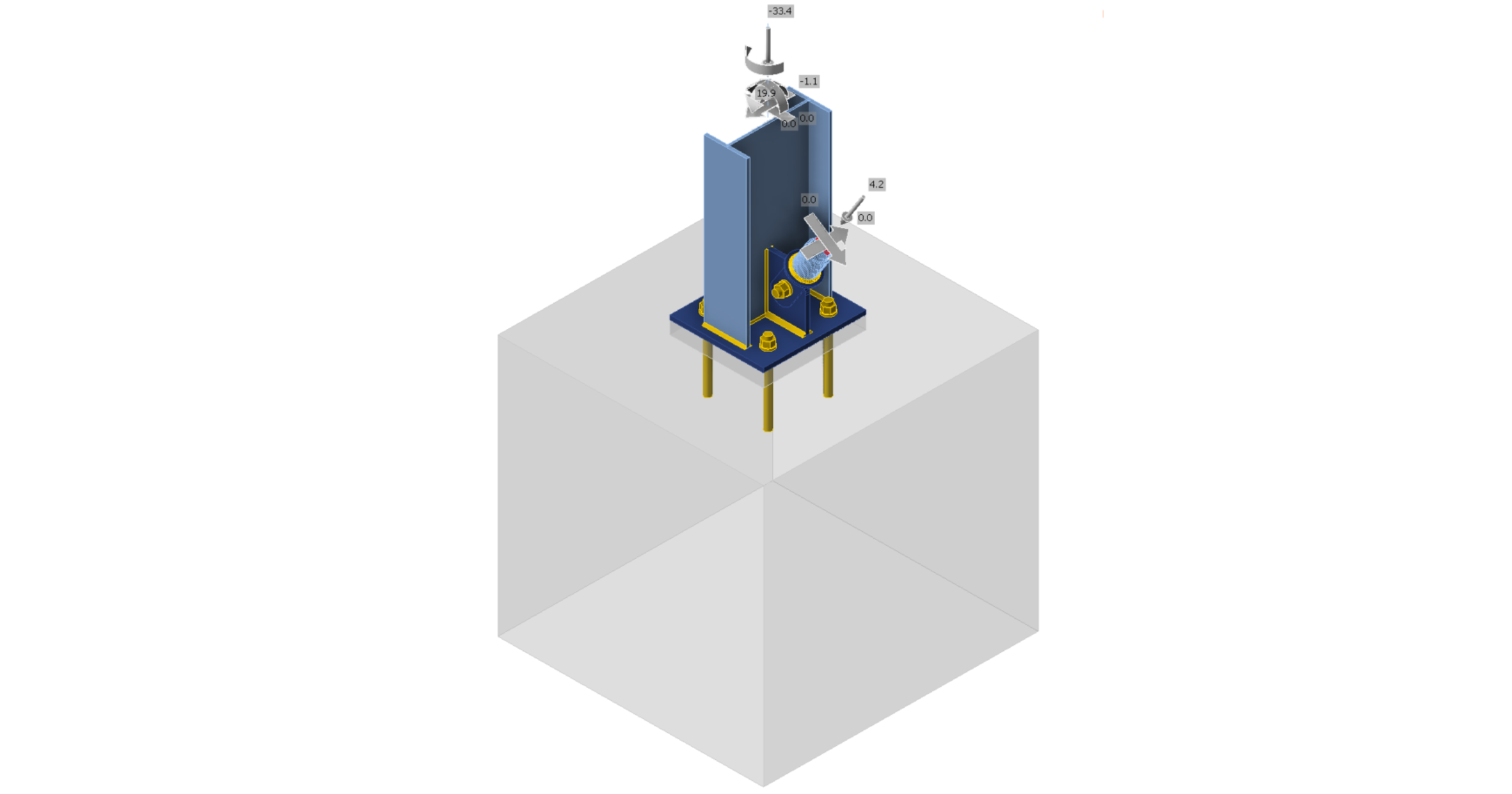
The results might not be acceptable. In this case, the anchors fail because of their low design capacity.

You can go to the Check tab to review the results and take a closer look at the anchors by expanding the calculation using the '+' symbol. You can see that the anchors are failing in tension in the concrete block.

We must optimize the design to find the passing solution. Go back to the Design tab, highlight the base plate operation, and change the Anchoring length to 200 mm and the concrete block Offset to 300 mm.

Run the analysis and code-check again.

Once the code-check is finished in the Report tab, you can create the report containing results and diagrams for your connection model.
The report can be printed or saved in several formats. For more information, please see here.

Save and Exit this connection back to Checkbot.
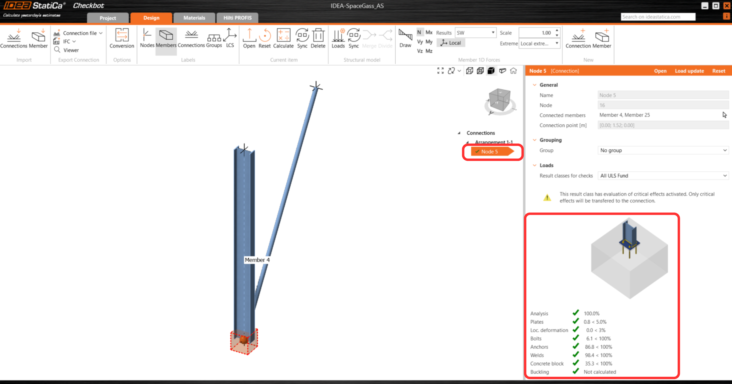
In Checkbot, you will see a green tick next to the connection. This means that the connection is valid and has passed all code-checks. In the Connection panel, you can also see a representation of the connection and a summary of the code-check results.
If multiple connections are present in Checkbot, then each must be opened, designed, and code-checked.
In the example below, you can see that baseplate connections have passed their respective code-checks whilst the remaining connections are yet to be validated.

You can continue with the design of additional connections - See how to model the roof connection with braces
Ontwerp synchroniseren
Soms verschijnen er wijzigingen in uw FEA/BIM-model, zoals andere afmetingen van de elementen of belastingen. Deze wijzigingen kunnen gesynchroniseerd worden tussen Checkbot en het FEA/BIM-model.
Er zijn twee mogelijke alternatieven:
- Het huidige item synchroniseren (als een of meer verbindingen geselecteerd worden)
- Het hele geïmporteerde structurele ontwerp synchroniseren
Om deze functie te testen kunt u in uw FEA/BIM app de grootte of vorm van een element wijzigen of een belastinggeval of combinatie wijzigen enz.: doorsnede van een geselecteerde kolom verkleinen. Vergeet niet het FEA-model opnieuw te analyseren.
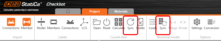
Selecteer de ontworpen verbindingen in Checkbot (er kunnen er meer dan één zijn) en selecteer Sync in het paneel Huidig item.
Het Checkbot-project wordt bijgewerkt, het ontwerp van de verbinding blijft behouden, maar de resultaten worden ongeldig gemaakt. U ziet dat de kolom nu is bijgewerkt - overeenkomstig de wijziging in het FEA-model.
Voer gewoon code-check van de gemarkeerde verbindingen opnieuw uit door Berekenen te selecteren in het paneel Huidig item. Vergeet niet dat grotere wijzigingen in het model aanvullende validatie met de betrokken verbindingen kunnen vereisen (zoals hierboven beschreven).
Als de verbindingen niet de gewenste resultaten opleveren, kunt u ze opnieuw openen om het ontwerp te optimaliseren (d.w.z. versterken als ze de code-check niet doorstaan of verlichten als de uitnutting te laag is).
You have successfully linked Space Gass with IDEA StatiCa Connection via Checkbot.