
Space Gass BIM link for the structural design of a steel connection (AS)
Jak aktivovat propojení
- Stáhněte si a nainstalujte (jako administrátor) nejnovější verzi IDEA StatiCa
- Ujistěte se, že používáte podporovanou verzi vašeho FEM/BIM programu
IDEA StatiCa se automaticky integruje do FEM/BIM softwaru během svojí instalace. Stav BIM propojení s jednotlivým software můžete spravovat v aplikaci Aktivace BIM propojení.
Vezměte prosím na vědomí, že některé FEM programy vyžadují další kroky, aby se plně aktivovalo jejich BIM propojení s IDEA StatiCa.
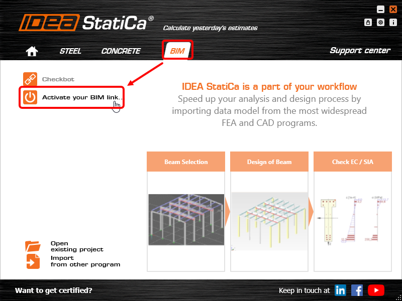
Otevřete IDEA StatiCa, přejděte na kartu BIM a otevřete instalační program BIM propojení (Activate your BIM link...).
Může se zobrazit oznámení "Chcete této aplikaci povolit provádět změny ve vašem zařízení?". Pokud ano, potvrďte jej tlačítkem Ano.
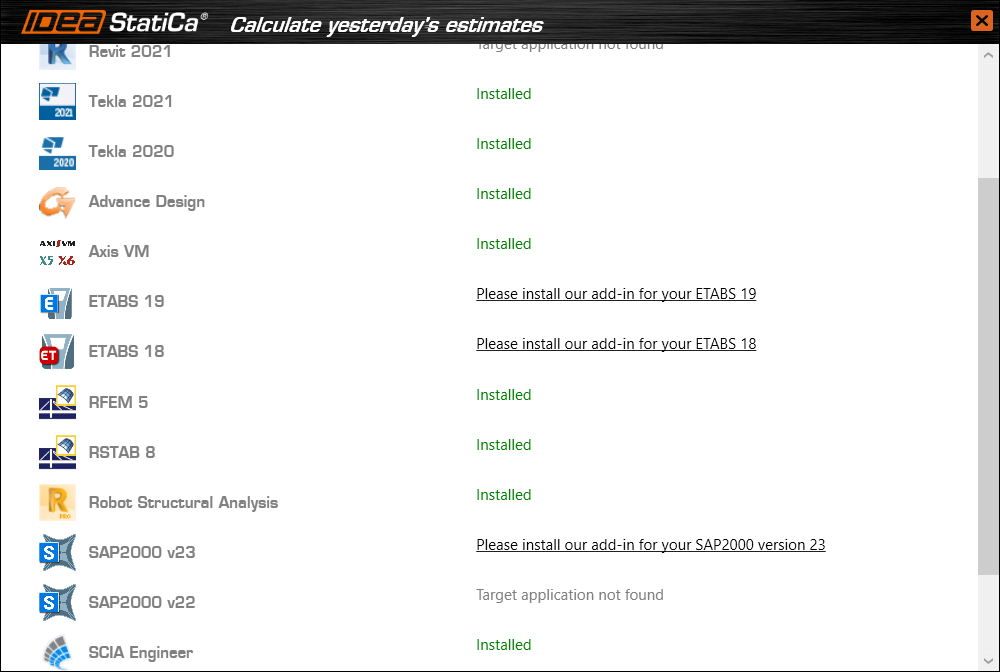
Nainstaluje se BIM propojení pro vybraný software (pokud byl nalezen). Na obrazovce se také zobrazí informace o stavu jiných BIM propojení, které již mohly být nainstalovány.
How to use the link
Open the attached AS Project in Space Gass and run the calculation.
The BIM link should be automatically integrated. You can find it in the top ribbon under Design -> IDEA StatiCa Checkbot. This will open the Checkbot application.

Select the New option with project type Steel, AS design code. Then select Create project.

The new Checkbot project is ready to import connections from Space Gass.
Import
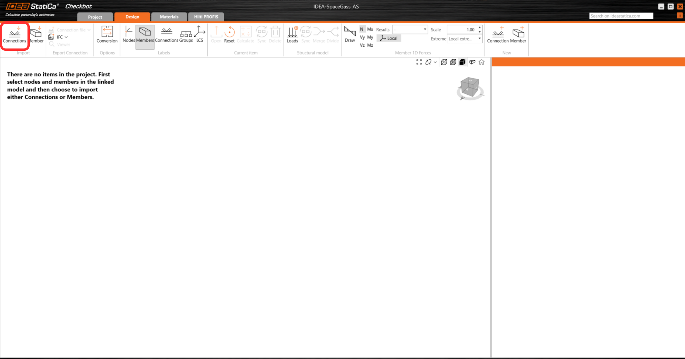
In Checkbot select Connections.
Then in Space Gass, select one of the inside columns lowest node, then right-click, select OK.
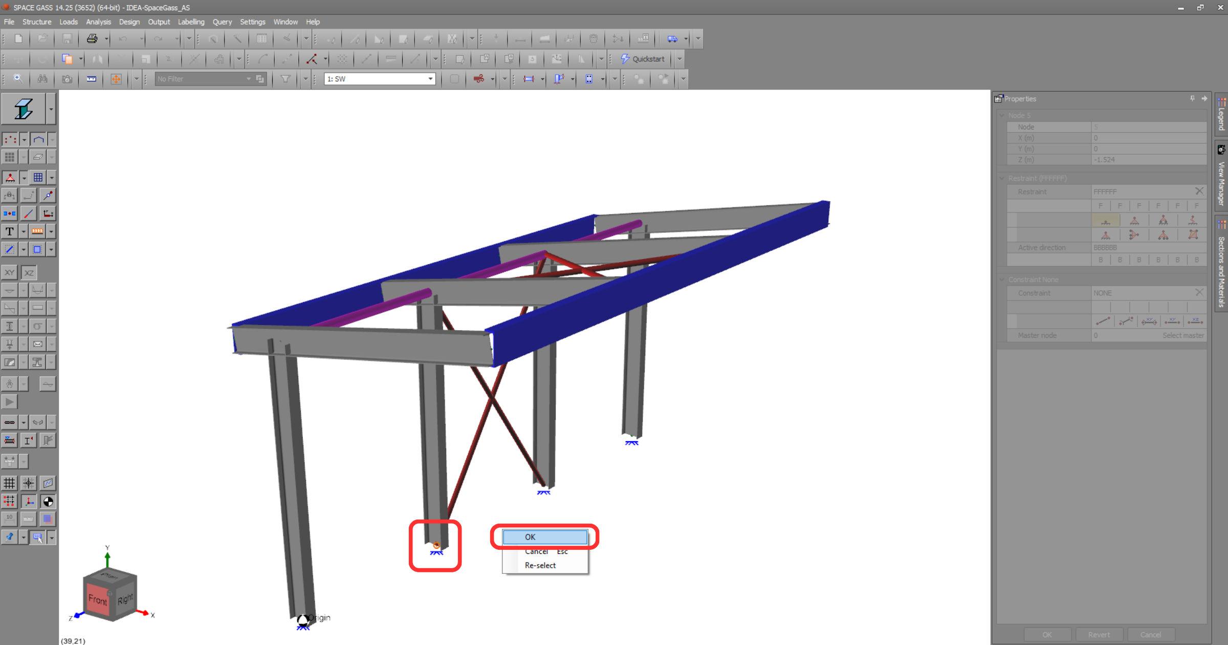
This will import the column and its load effects into Checkbot - with the same coordinates, orientations, and section sizes as per the FEA/BIM model.
Please note that your node and member numbering might be different.
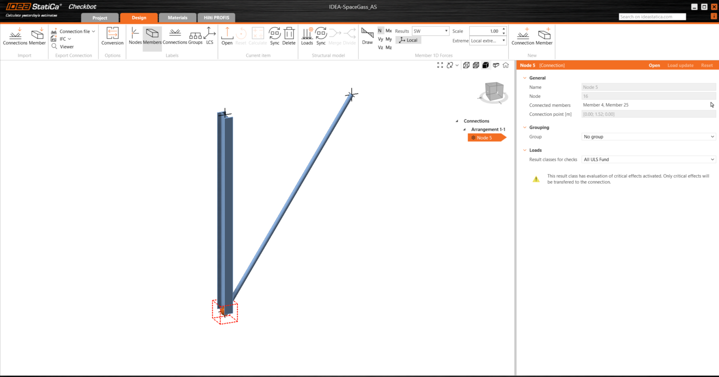
Please note the 3D workspace is designed to show an overview of the imported structure and not a detailed view of the actual connections.
For more information on Checkbot, see here.
For several FEA/BIM solutions, you can also import multiple connections into Checkbot in the same manner as above. Instead of selecting one node and the connected members, you can select several nodes and members using the selection methods within the application.
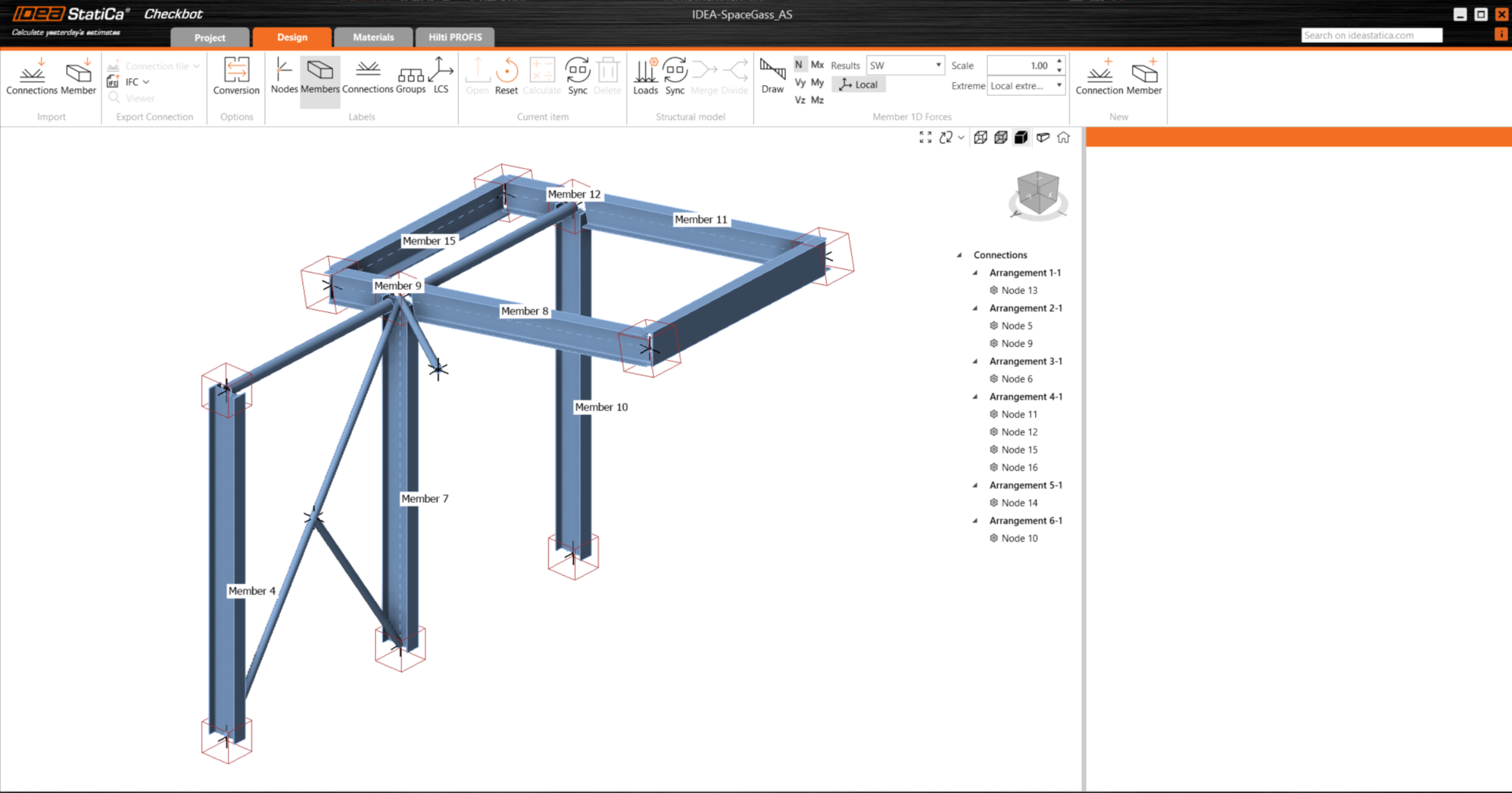
We recommend not importing all of the connections at the same time but building up the connections incrementally.
Geometry
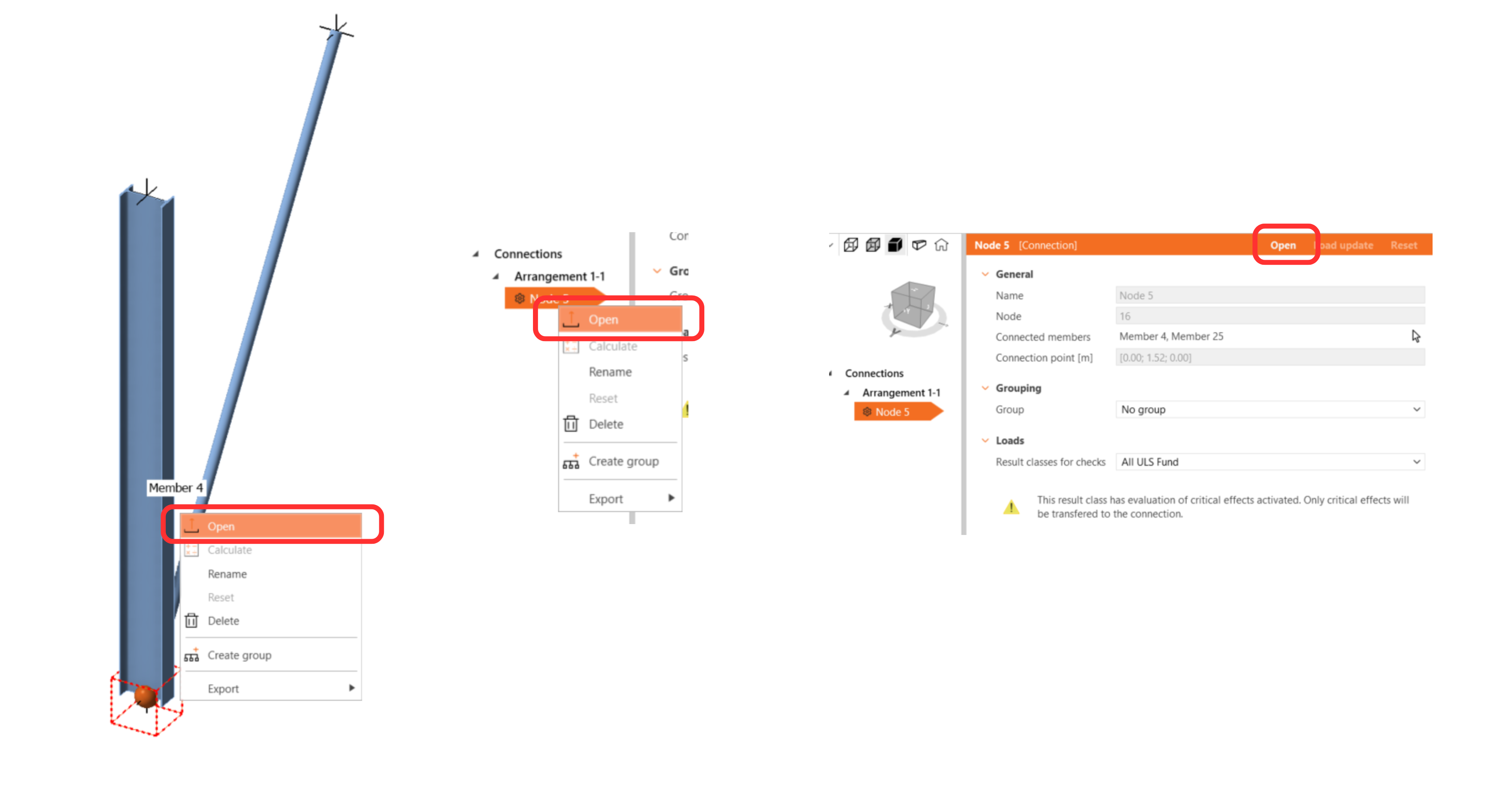
In the list of project items under Connections and with a connection highlighted in Checkbot you can either right-mouse click and select Open or click the ribbon command Open to start designing, code-checking, and reporting.
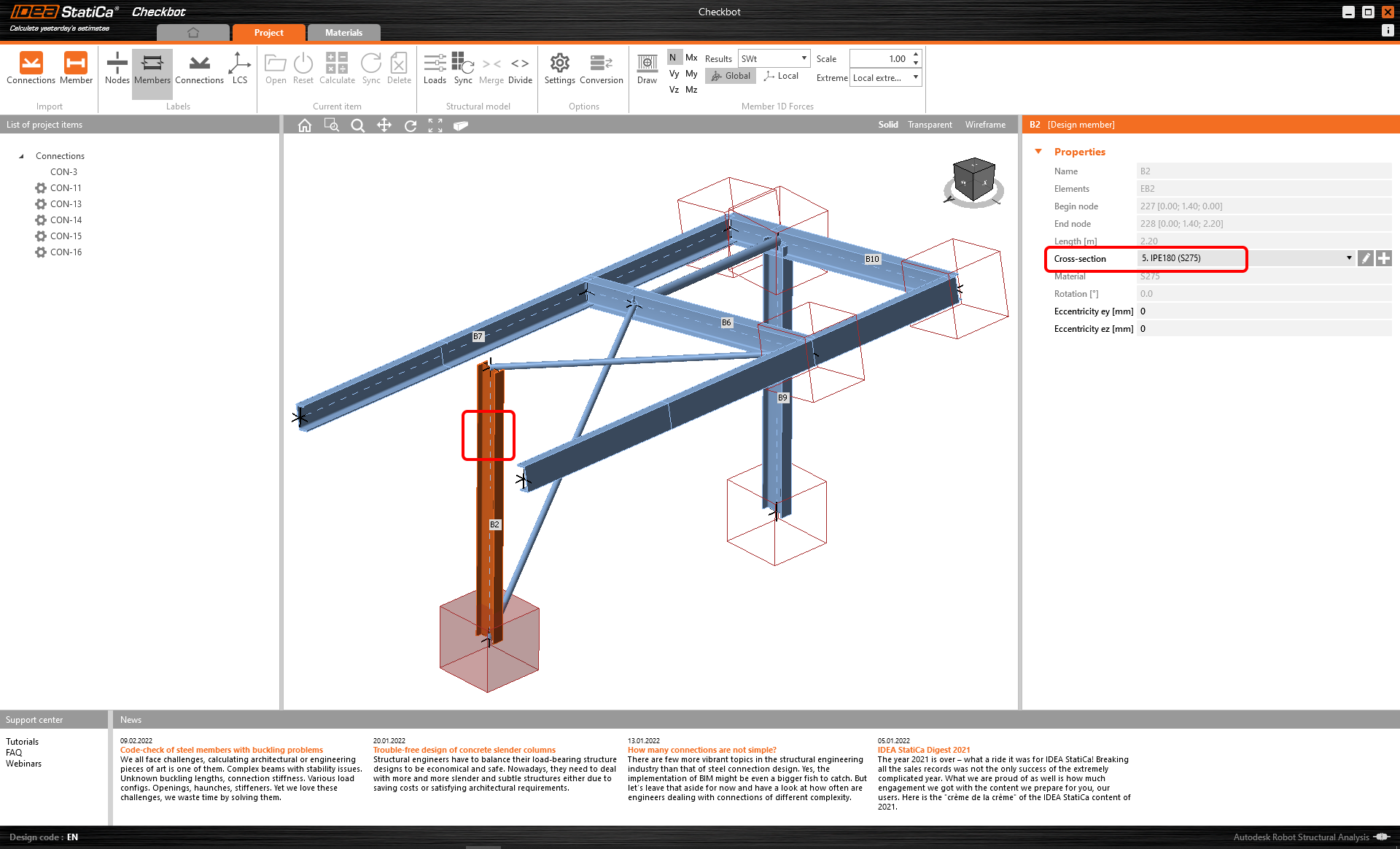
The settings of members are taken from the original FEA/BIM application. You can, however, change the section size of any member on the main Checkbot screen, but this will break the link with FEA/BIM application in this session unless it's synchronized again.
The imported connection is opened in the IDEA StatiCa Connection application.

You may see none or different Load effects from your preferred FEA/BIM* solution depending on how the load case combinations have been defined. By default, IDEA StatiCa will choose the most critical for code-checking purposes. (* Some BIM solutions are not able to store the load case combination results)
For more information on Load effects see here.
Design
We are going to be using a single bolt connection for the diagonal brace. For this type of connection, we must also change the Model type of the brace member to N-Vy-Vz. Select the brace in the list of Members and modify the Model type in the drop-down list.

We are going to use the Connection Library to generate a connection. Select Propose and IDEA StatiCa will put forward possible solutions for the current geometry.
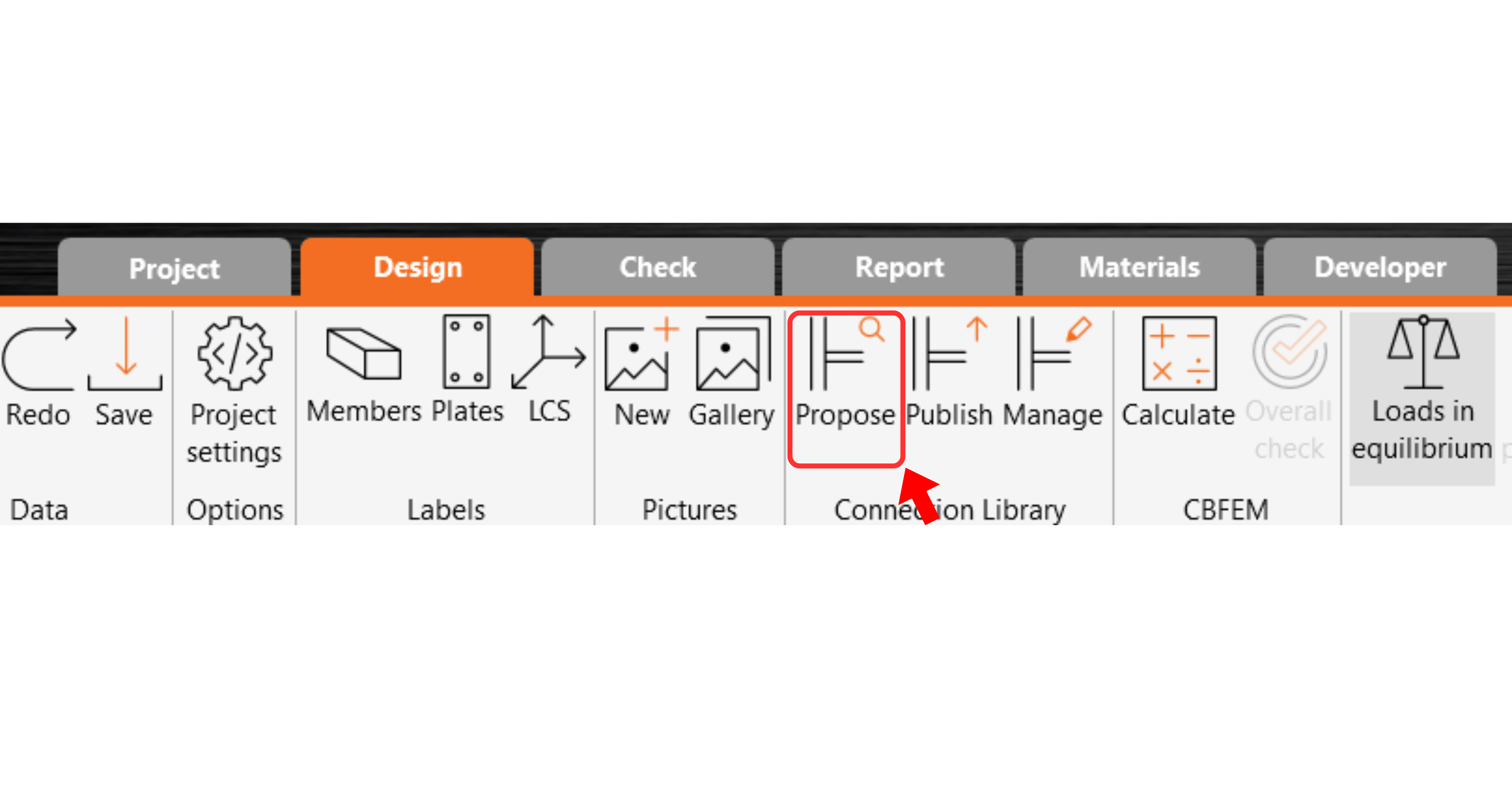
Connection Library shows you the possible solutions for the current geometry. Choose the template offered and press OK.

Accept the proposed values for the bolts and concrete block and press OK.

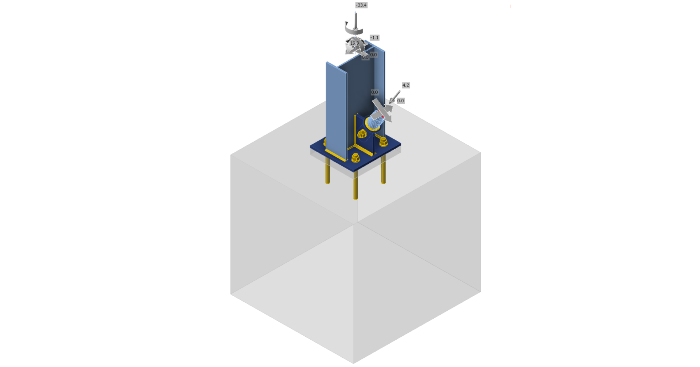
This is what the initial connection looks like.
With these default parameters for the Base plate.

These are the parameters for the Connecting plate.

That completes the design of the connection for the column base plate with a diagonal brace.
Code-check and Report
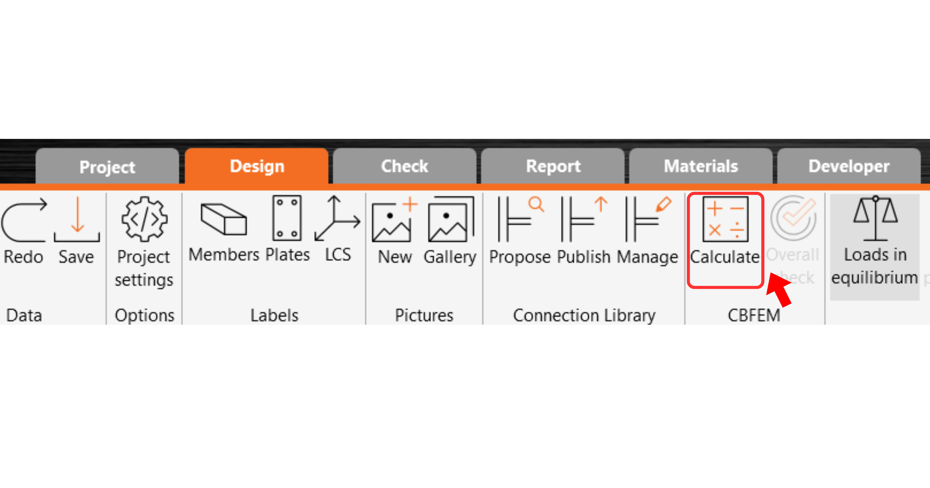
Now run a code-check using the Calculate icon in the CBFEM panel from the top ribbon.
Within IDEA StatiCa Connection, you can carry out many different types of analysis and code-checks. For more information, please see here.
The results might not be acceptable. In this case, the anchors fail because of their low design capacity.

You can go to the Check tab to review the results and take a closer look at the anchors by expanding the calculation using the '+' symbol. You can see that the anchors are failing in tension in the concrete block.

We must optimize the design to find the passing solution. Go back to the Design tab, highlight the base plate operation, and change the Anchoring length to 200 mm and the concrete block Offset to 300 mm.

Run the analysis and code-check again.

Once the code-check is finished in the Report tab, you can create the report containing results and diagrams for your connection model.
The report can be printed or saved in several formats. For more information, please see here.

Save and Exit this connection back to Checkbot.
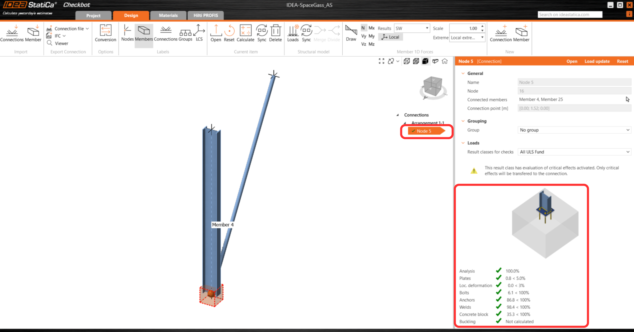
In Checkbot, you will see a green tick next to the connection. This means that the connection is valid and has passed all code-checks. In the Connection panel, you can also see a representation of the connection and a summary of the code-check results.
If multiple connections are present in Checkbot, then each must be opened, designed, and code-checked.
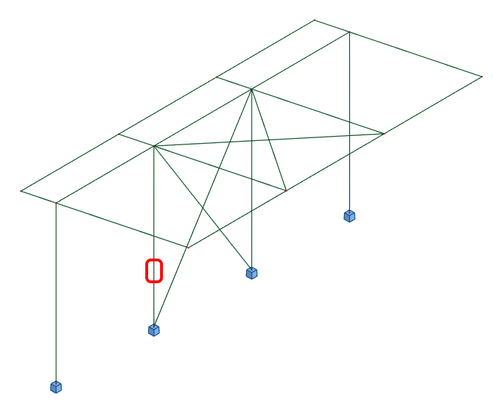
In the example below, you can see that baseplate connections have passed their respective code-checks whilst the remaining connections are yet to be validated.

You can continue with the design of additional connections - See how to model the roof connection with braces
Synchronizace modelu
Někdy dojde ke změnám v modelu FEM/BIM, například se změní velikost průřezu prutu nebo zatížení. Tyto změny lze synchronizovat mezi Checkbotem a modelem FEM/BIM.
Existují dvě možné alternativy:
- Synchronizace aktuální položky (pokud je vybrán jeden nebo více uzlů)
- Synchronizovat celý importovaný model konstrukce
Chcete-li tuto funkci vyzkoušet, můžete v aplikaci FEM/BIM změnit velikost nebo tvar průřezu prutu případně změnit zatěžovací stav nebo kombinaci atd.: změnit u sloupů profil na menší průřez. Nezapomeňte znovu analyzovat model FEM.
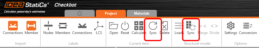
V aplikaci Checkbot vyberte navržené připoje (může jich být více) a na panelu Aktuální položka vyberte možnost Synchronizace.
Projekt Checkbot bude aktualizován, návrh přípoje zůstane zachován, ale výsledky budou zneplatněny. Vidíte, že sloupec je nyní aktualizován - odpovídá změně v modelu FEM.
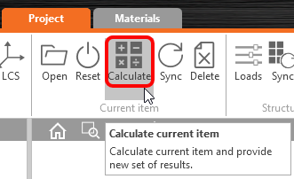
Zvýrazněné přípoje jednoduše znovu posuďte výběrem možnosti Vypočítat na panelu Aktuální položka. Nezapomeňte, že větší změny v modelu mohou vyžadovat další kroky validace s dotčenými přípoji (jak je uvedeno výše).
Pokud přípoje neposkytnou požadované výsledky, můžete je znovu otevřít a optimalizovat návrh (tj. zesílit, pokud neprojdou posouzením, nebo odlehčit, pokud je využití některých částí příliš nízké).
You have successfully linked Space Gass with IDEA StatiCa Connection via Checkbot.