
Space Gass BIM link for the structural design of a steel connection (AS)
Come attivare il collegamento
- Scaricare e installare l'ultima versione di IDEA StatiCa.
- Assicurarsi di utilizzare una versione supportata della propria soluzione FEA/BIM.
IDEA StatiCa integra i collegamenti BIM nelle soluzioni FEA/BIM durante la sua installazione. È possibile controllare lo stato e attivare altri collegamenti BIM per i software installati successivamente nel programma di installazione dei collegamenti BIM.
Si noti che alcune soluzioni FEA richiedono ulteriori passaggi per attivare completamente il loro collegamento BIM a IDEA StatiCa.
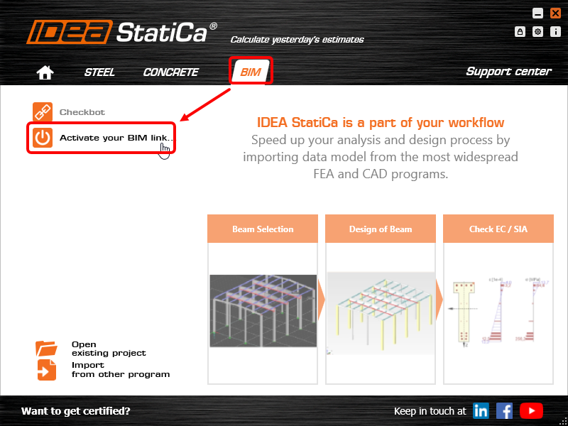
Apri IDEA StatiCa e naviga nella scheda BIM. Clicca su Attiva il tuo collegamento BIM... (Activate your BIM link...).
Potrebbe apparire la notifica "Vuoi consentire a questa applicazione di apportare modifiche al tuo dispositivo?"; in tal caso, confermare con il pulsante Sì.
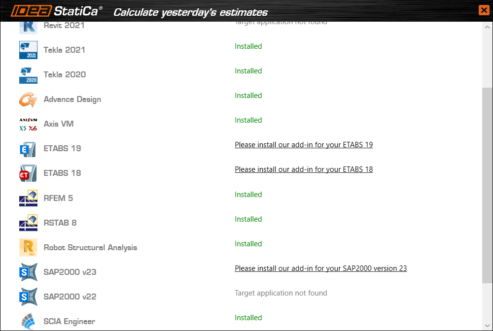
Installare il collegamento BIM per il software selezionato (se trovato). La schermata indica anche lo stato di altri collegamenti BIM eventualmente già installati (Intalled).
How to use the link
Open the attached AS Project in Space Gass and run the calculation.
The BIM link should be automatically integrated. You can find it in the top ribbon under Design -> IDEA StatiCa Checkbot. This will open the Checkbot application.

Select the New option with project type Steel, AS design code. Then select Create project.

The new Checkbot project is ready to import connections from Space Gass.
Import
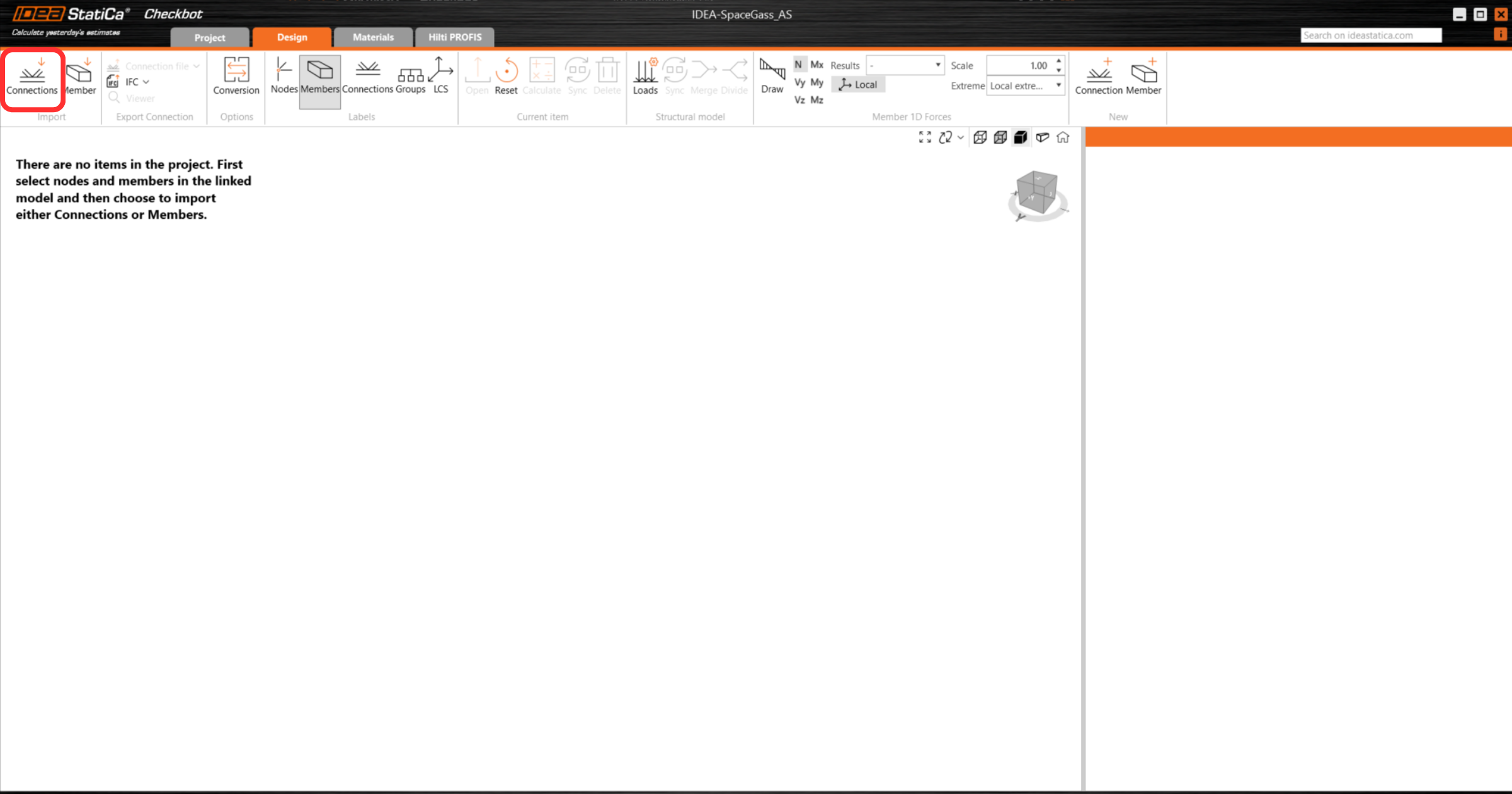
In Checkbot select Connections.
Then in Space Gass, select one of the inside columns lowest node, then right-click, select OK.
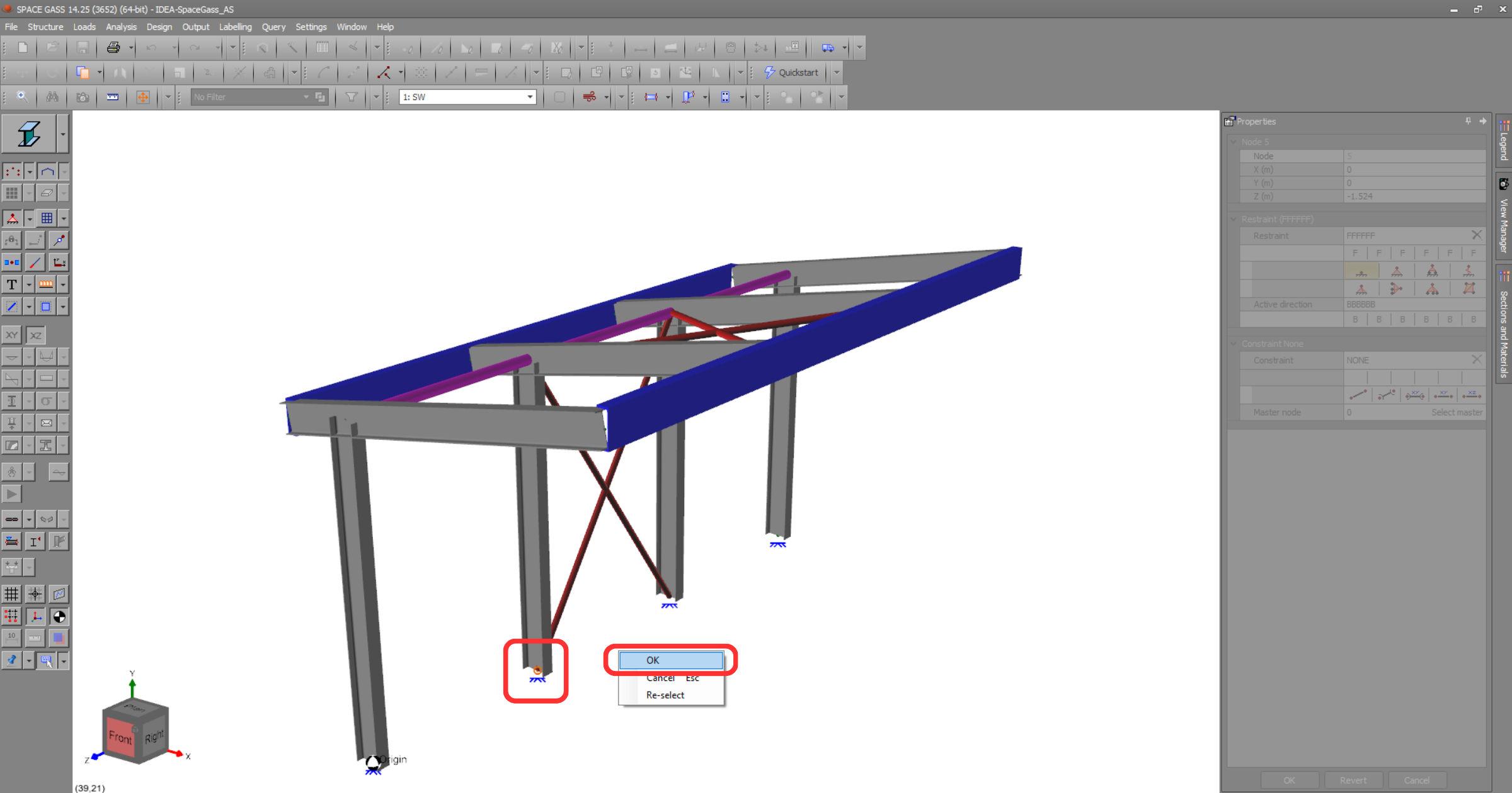
This will import the column and its load effects into Checkbot - with the same coordinates, orientations, and section sizes as per the FEA/BIM model.
Please note that your node and member numbering might be different.
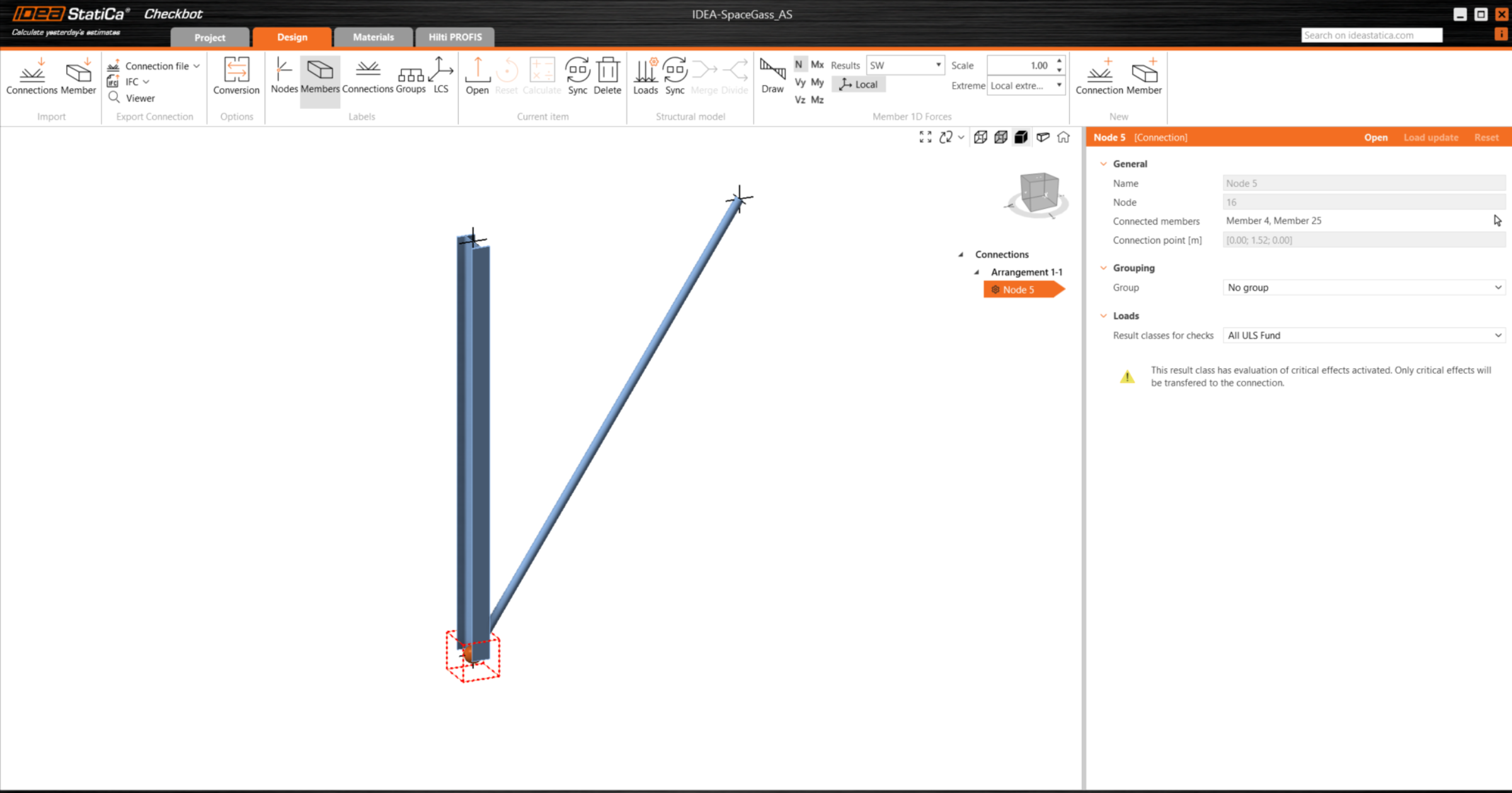
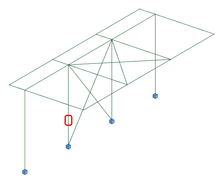
Please note the 3D workspace is designed to show an overview of the imported structure and not a detailed view of the actual connections.
For more information on Checkbot, see here.
For several FEA/BIM solutions, you can also import multiple connections into Checkbot in the same manner as above. Instead of selecting one node and the connected members, you can select several nodes and members using the selection methods within the application.
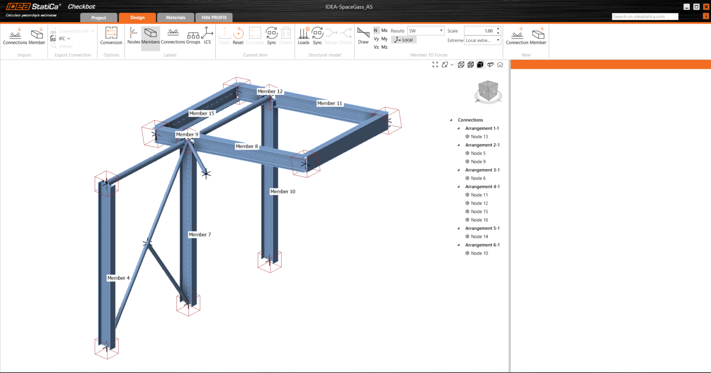
We recommend not importing all of the connections at the same time but building up the connections incrementally.
Geometry
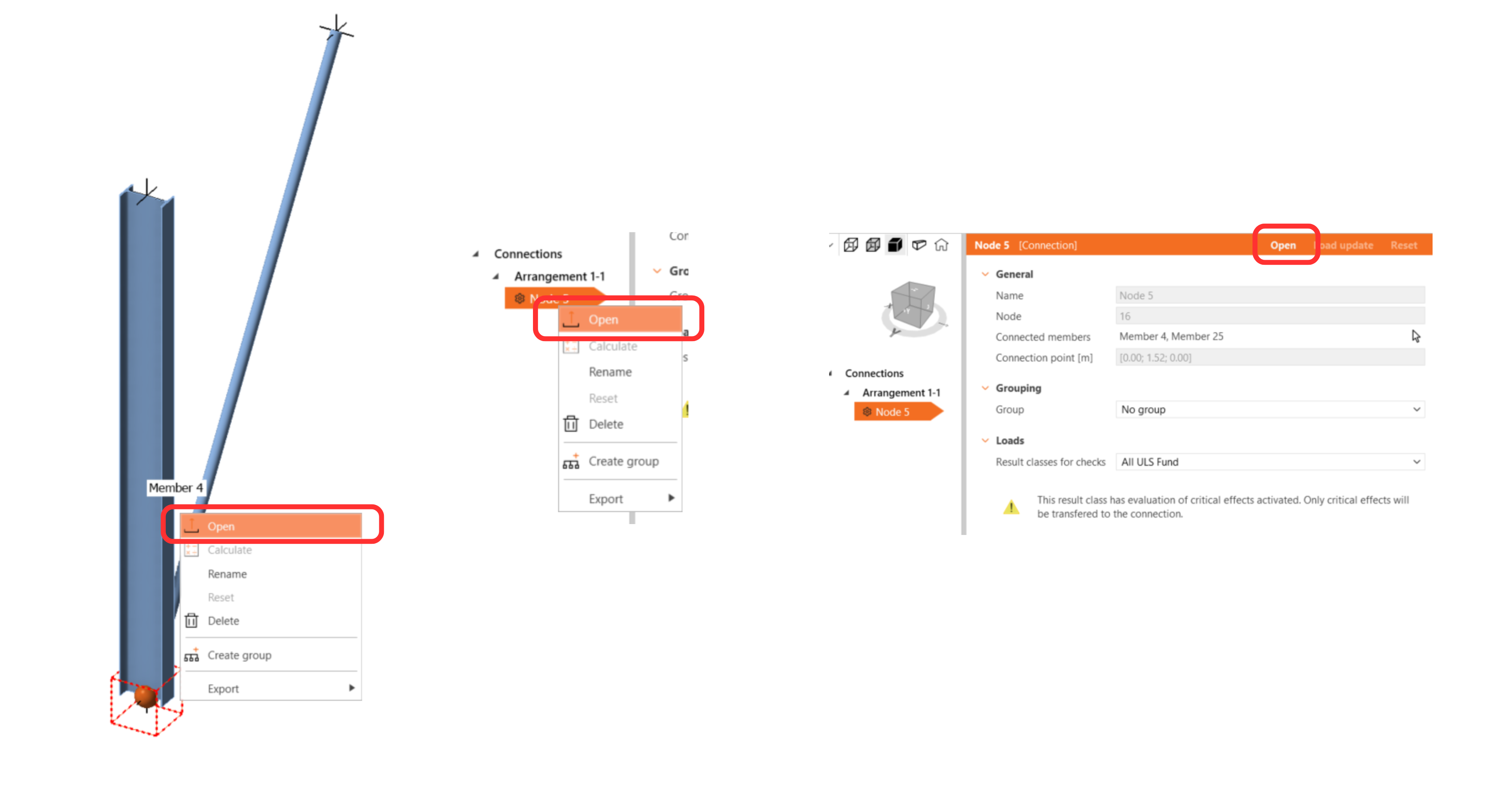
In the list of project items under Connections and with a connection highlighted in Checkbot you can either right-mouse click and select Open or click the ribbon command Open to start designing, code-checking, and reporting.
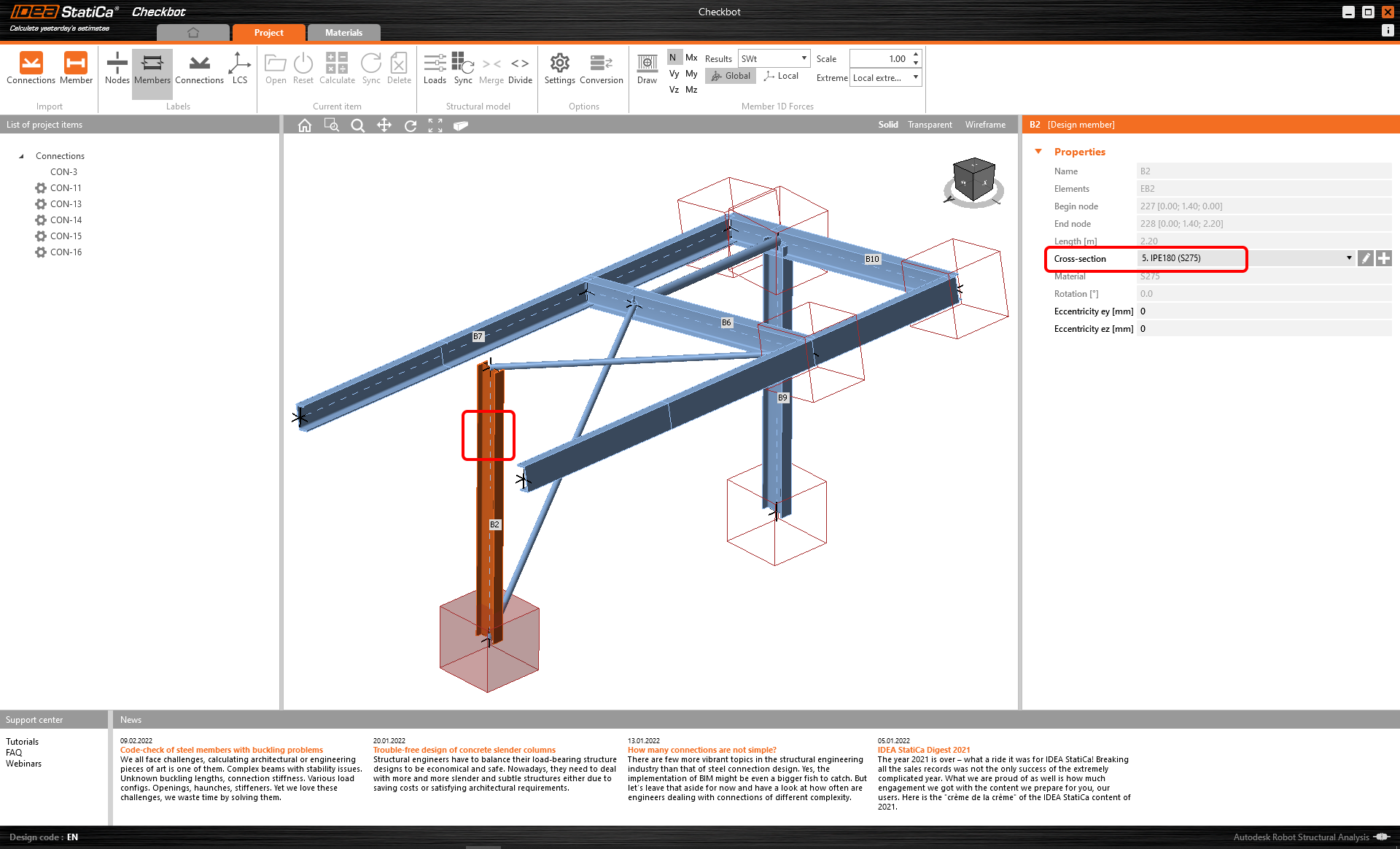
The settings of members are taken from the original FEA/BIM application. You can, however, change the section size of any member on the main Checkbot screen, but this will break the link with FEA/BIM application in this session unless it's synchronized again.
The imported connection is opened in the IDEA StatiCa Connection application.

You may see none or different Load effects from your preferred FEA/BIM* solution depending on how the load case combinations have been defined. By default, IDEA StatiCa will choose the most critical for code-checking purposes. (* Some BIM solutions are not able to store the load case combination results)
For more information on Load effects see here.
Design
We are going to be using a single bolt connection for the diagonal brace. For this type of connection, we must also change the Model type of the brace member to N-Vy-Vz. Select the brace in the list of Members and modify the Model type in the drop-down list.

We are going to use the Connection Library to generate a connection. Select Propose and IDEA StatiCa will put forward possible solutions for the current geometry.
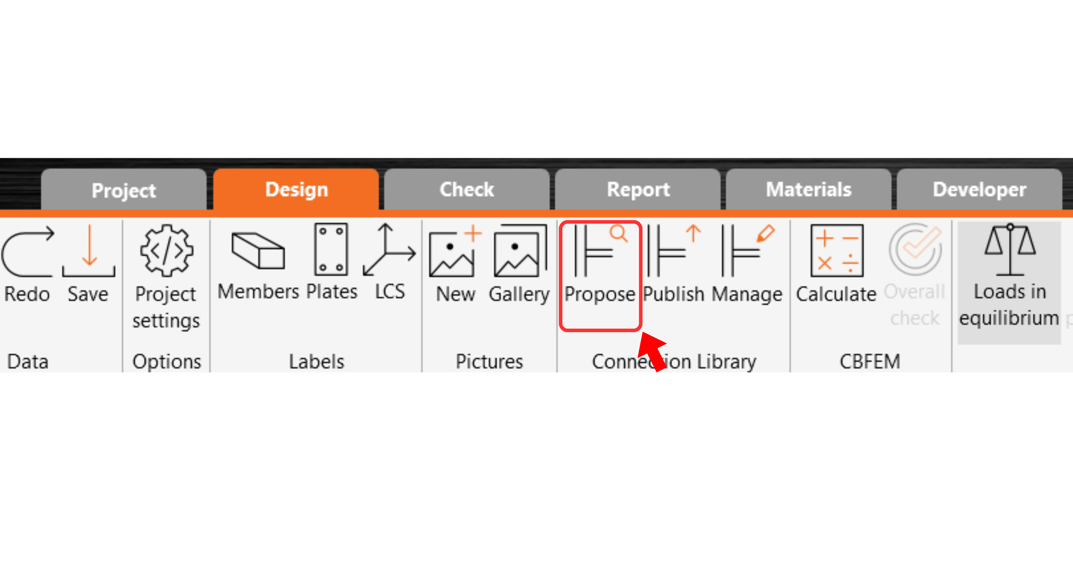
Connection Library shows you the possible solutions for the current geometry. Choose the template offered and press OK.

Accept the proposed values for the bolts and concrete block and press OK.

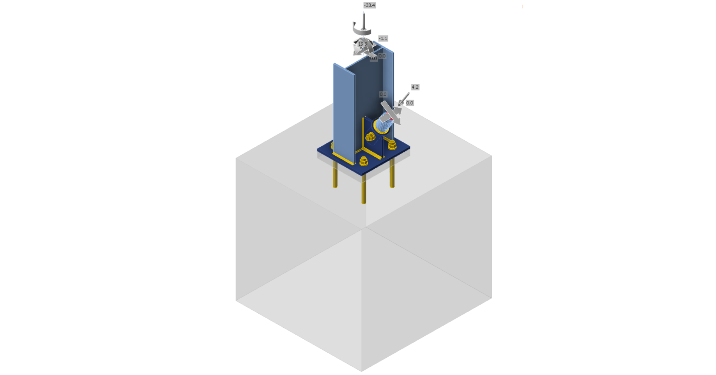
This is what the initial connection looks like.
With these default parameters for the Base plate.

These are the parameters for the Connecting plate.

That completes the design of the connection for the column base plate with a diagonal brace.
Code-check and Report
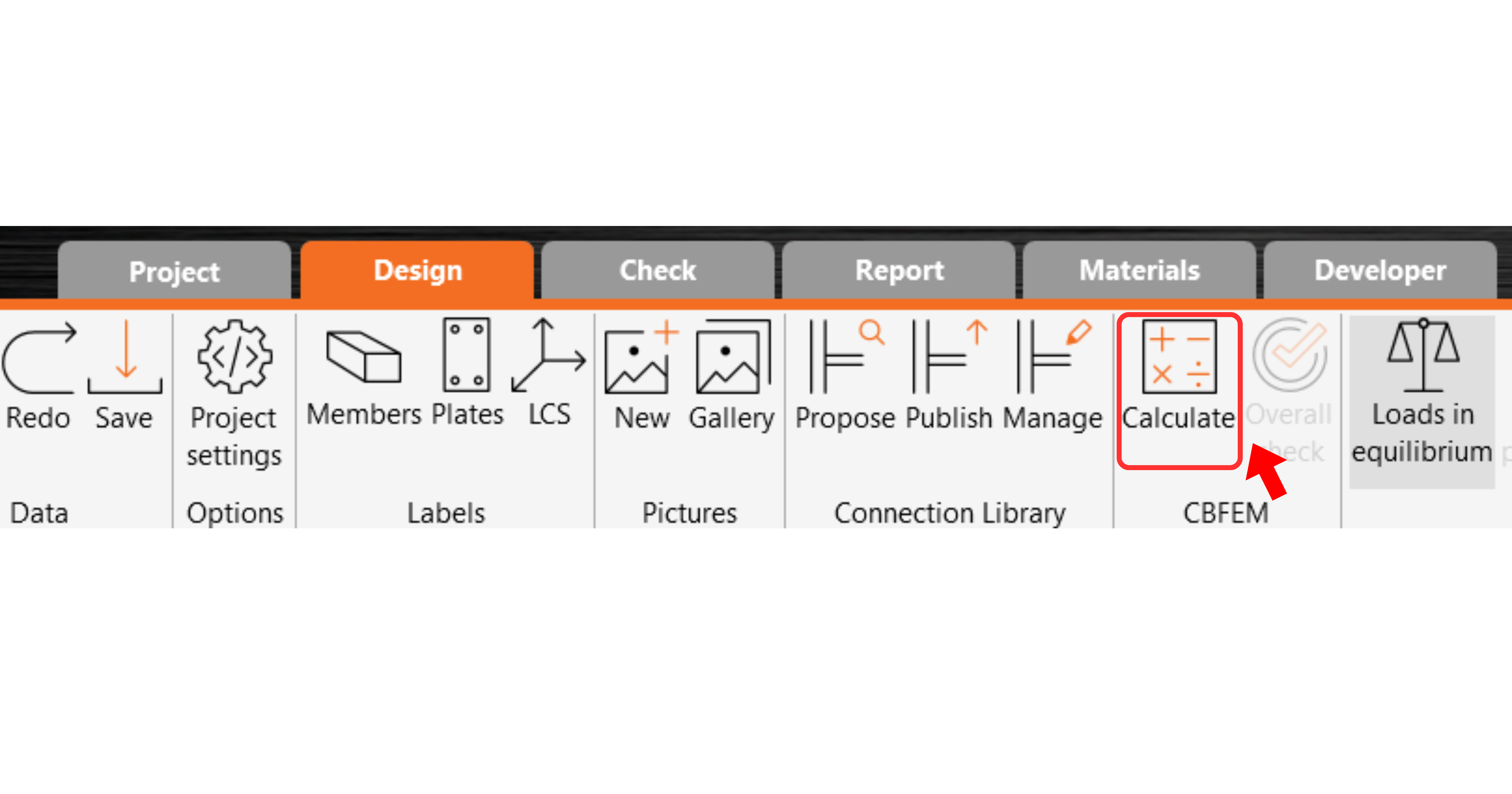
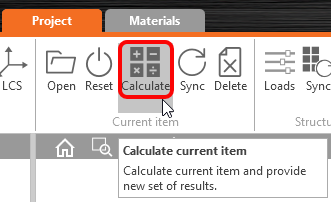
Now run a code-check using the Calculate icon in the CBFEM panel from the top ribbon.
Within IDEA StatiCa Connection, you can carry out many different types of analysis and code-checks. For more information, please see here.
The results might not be acceptable. In this case, the anchors fail because of their low design capacity.

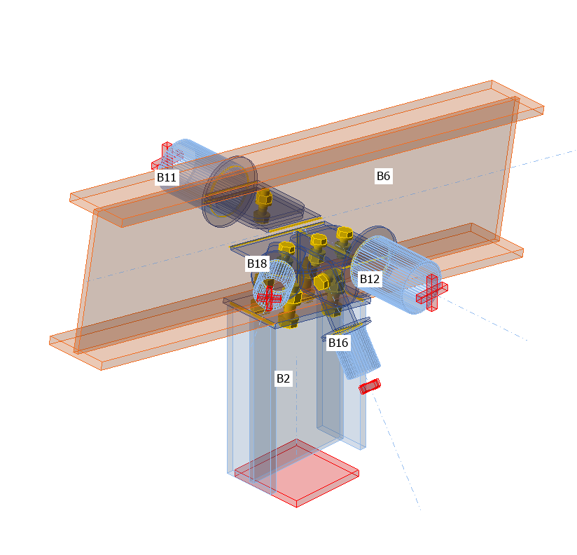
You can go to the Check tab to review the results and take a closer look at the anchors by expanding the calculation using the '+' symbol. You can see that the anchors are failing in tension in the concrete block.

We must optimize the design to find the passing solution. Go back to the Design tab, highlight the base plate operation, and change the Anchoring length to 200 mm and the concrete block Offset to 300 mm.

Run the analysis and code-check again.

Once the code-check is finished in the Report tab, you can create the report containing results and diagrams for your connection model.
The report can be printed or saved in several formats. For more information, please see here.

Save and Exit this connection back to Checkbot.
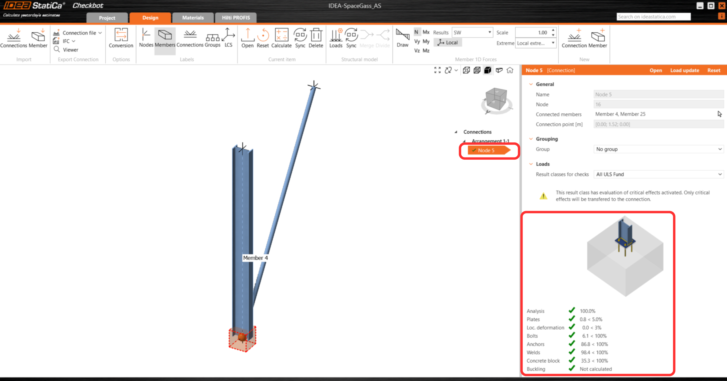
In Checkbot, you will see a green tick next to the connection. This means that the connection is valid and has passed all code-checks. In the Connection panel, you can also see a representation of the connection and a summary of the code-check results.
If multiple connections are present in Checkbot, then each must be opened, designed, and code-checked.
In the example below, you can see that baseplate connections have passed their respective code-checks whilst the remaining connections are yet to be validated.

You can continue with the design of additional connections - See how to model the roof connection with braces
Sincronizza le connessioni
A volte, ci vengono apportate modifiche al modello FEA/BIM, come dimensioni o carichi diversi oppure nella sezione della membratura. Queste modifiche possono essere sincronizzate tra Checkbot e modello FEA/BIM.
Ci sono due possibili alternative:
- Sincronizzare l'elemento corrente (se sono selezionati uno o più giunti)
- Sincronizzare l'intero modello strutturale importato
Per testare questa funzionalità, è possibile modificare la dimensione o la forma di una sezione dell'elemento nell'applicazione FEA/BIM o modificare un caso o una combinazione di carico, ecc.: modifica le colonne in una sezione più piccola. Ricordati di ricalcolare il modello FEA.
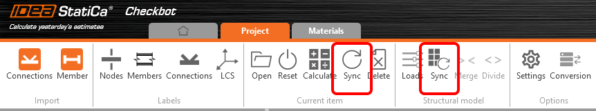
In Checkbot seleziona le connessioni progettate (potrebbero essercene più di una) e dal pannello Elemento corrente seleziona Sync per sincronizzare.
Il progetto Checkbot verrà aggiornato, la progettazione della connessione verrà preservata, ma i risultati verranno invalidati. Puoi vedere che la colonna è ora aggiornata e corrispondente alla modifica nel modello FEA.
È sufficiente verificare nuovamente le connessioni evidenziate selezionando Calcola dal pannello Elemento corrente. Tieni presente che cambiamenti più importanti nel modello potrebbero richiedere ulteriori passaggi di convalida con le connessioni interessate (come sopra).
Se le connessioni non danno i risultati desiderati, è possibile riaprirle per ottimizzare la progettazione (ad esempio rafforzarle se non sono verificate o alleggerirle e ottimizzare i materiali se l'utilizzo è troppo basso).
You have successfully linked Space Gass with IDEA StatiCa Connection via Checkbot.