
Space Gass BIM link for the structural design of a steel connection (AS)
So aktivieren Sie den Link
- Downloaden und installieren Sie (als Administrator) die aktuelle Version von IDEA StatiCa
- Vergewissern Sie sich, dass Sie die unterstützte Version verwenden
IDEA StatiCa integriert den BIM-Link während der Installation automatisch in Ihre FEA-/BIM-Lösung. Sie können den Status überprüfen und weitere BIM-Links für nachträglich installierte Software im BIM-Link-Installer aktivieren.
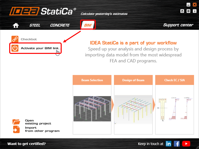
Öffnen Sie IDEA StatiCa und navigieren Sie zum Bereich BIM und öffnen Sie den BIM Link Installer. Eventuell erscheint eine Meldung Als Administrator ausführen, bitte bestätigen Sie mit Ja.
Bitte beachten Sie, dass einige FEA-Lösungen zusätzliche Schritte erfordern, um ihre BIM-Verbindung zu IDEA StatiCa vollständig zu aktivieren.
Öffnen Sie IDEA StatiCa und navigieren Sie zum Tab BIM und öffnen Sie den BIM-Link-Installer (Aktivieren deinen BIM-Link...).
Eine Benachrichtigung "Möchten Sie zulassen, dass diese Anwendung Änderungen an Ihrem Gerät vornimmt?" erscheinen, wenn ja, bestätigen Sie dies bitte mit Ja.
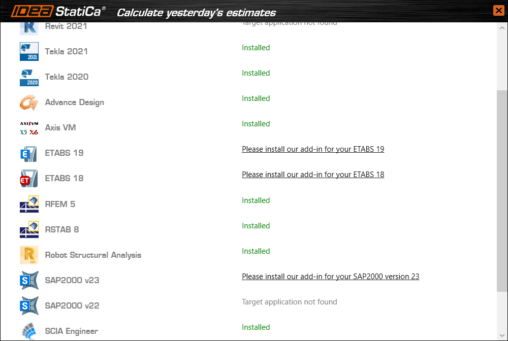
Der BIM-Link für die ausgewählte Software (falls gefunden) wird installiert. Der Bildschirm informiert Sie auch über den Status anderer BIM-Links, die möglicherweise bereits installiert wurden.
How to use the link
Open the attached AS Project in Space Gass and run the calculation.
The BIM link should be automatically integrated. You can find it in the top ribbon under Design -> IDEA StatiCa Checkbot. This will open the Checkbot application.

Select the New option with project type Steel, AS design code. Then select Create project.

The new Checkbot project is ready to import connections from Space Gass.
Import
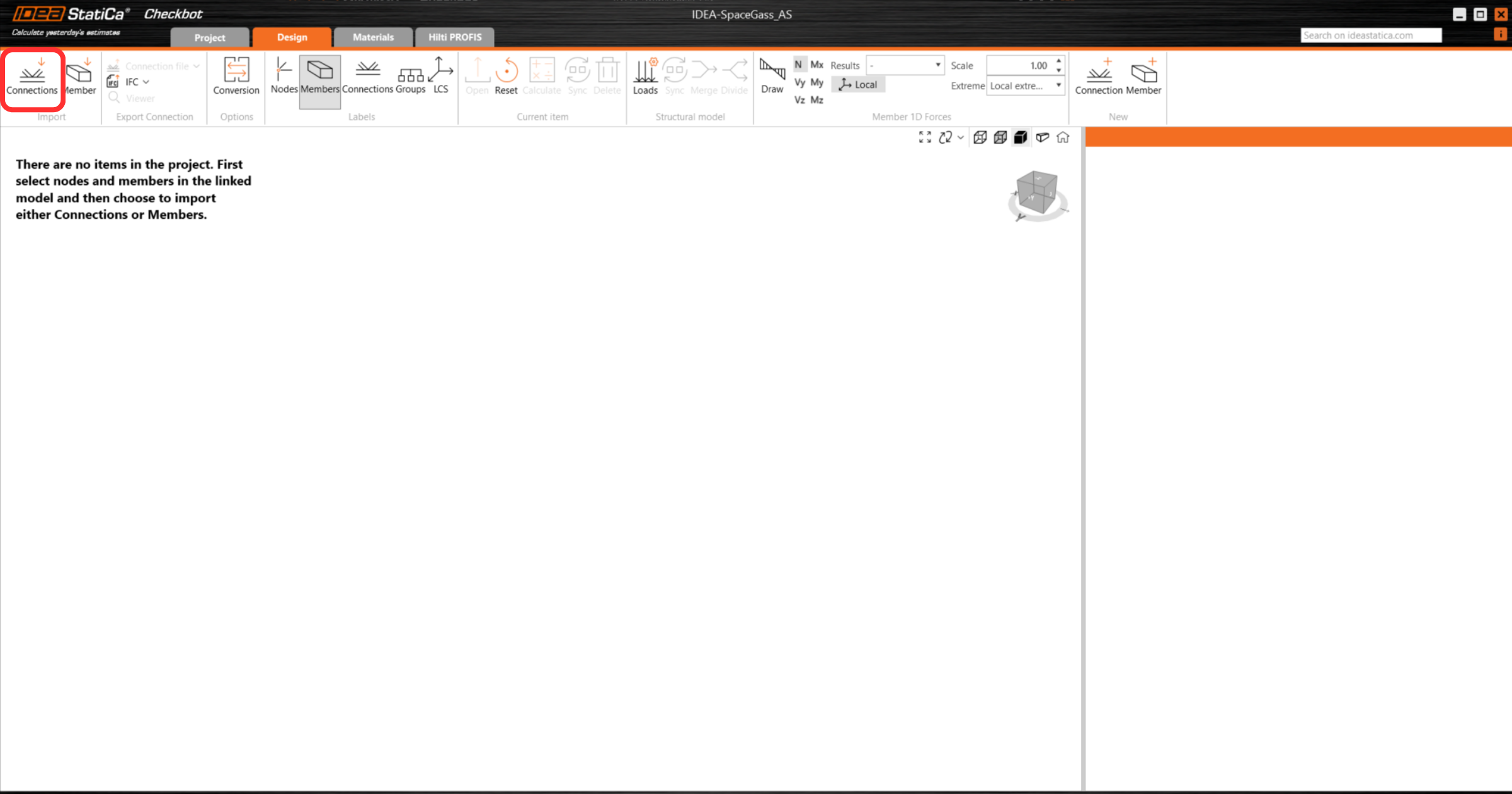
In Checkbot select Connections.
Then in Space Gass, select one of the inside columns lowest node, then right-click, select OK.
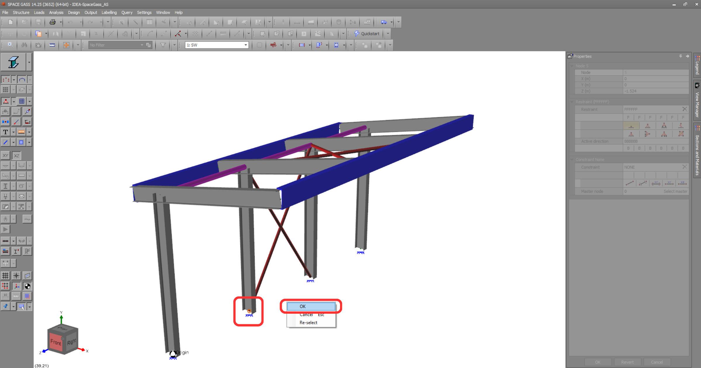
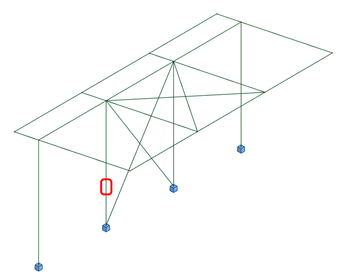
This will import the column and its load effects into Checkbot - with the same coordinates, orientations, and section sizes as per the FEA/BIM model.
Please note that your node and member numbering might be different.
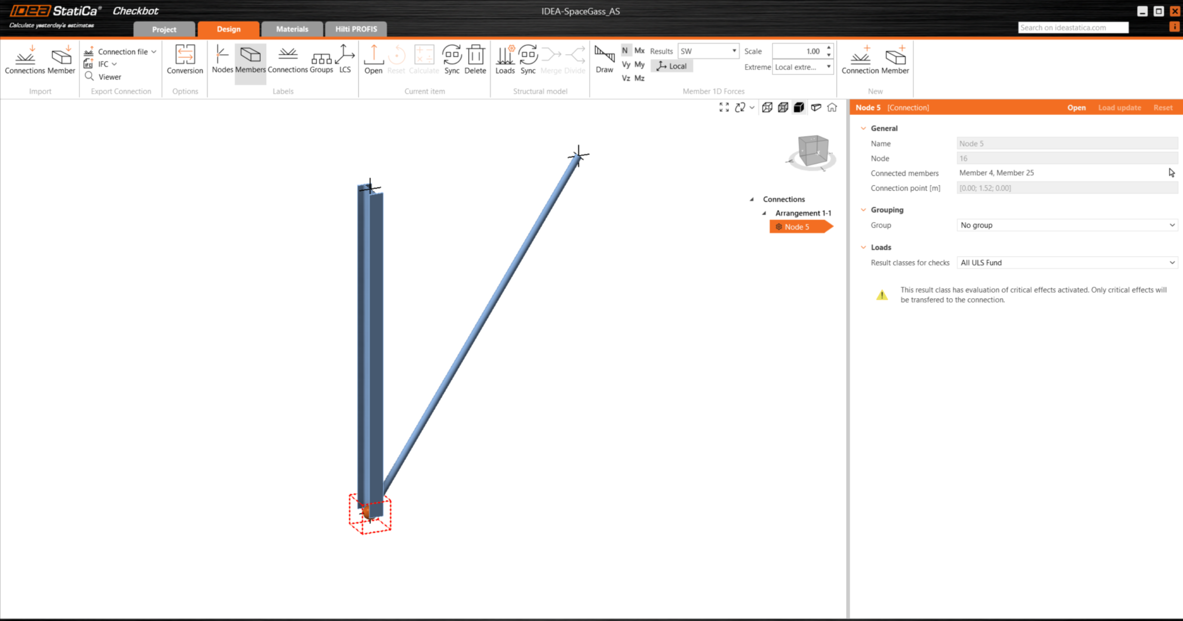
Please note the 3D workspace is designed to show an overview of the imported structure and not a detailed view of the actual connections.
For more information on Checkbot, see here.
For several FEA/BIM solutions, you can also import multiple connections into Checkbot in the same manner as above. Instead of selecting one node and the connected members, you can select several nodes and members using the selection methods within the application.
We recommend not importing all of the connections at the same time but building up the connections incrementally.
Geometry
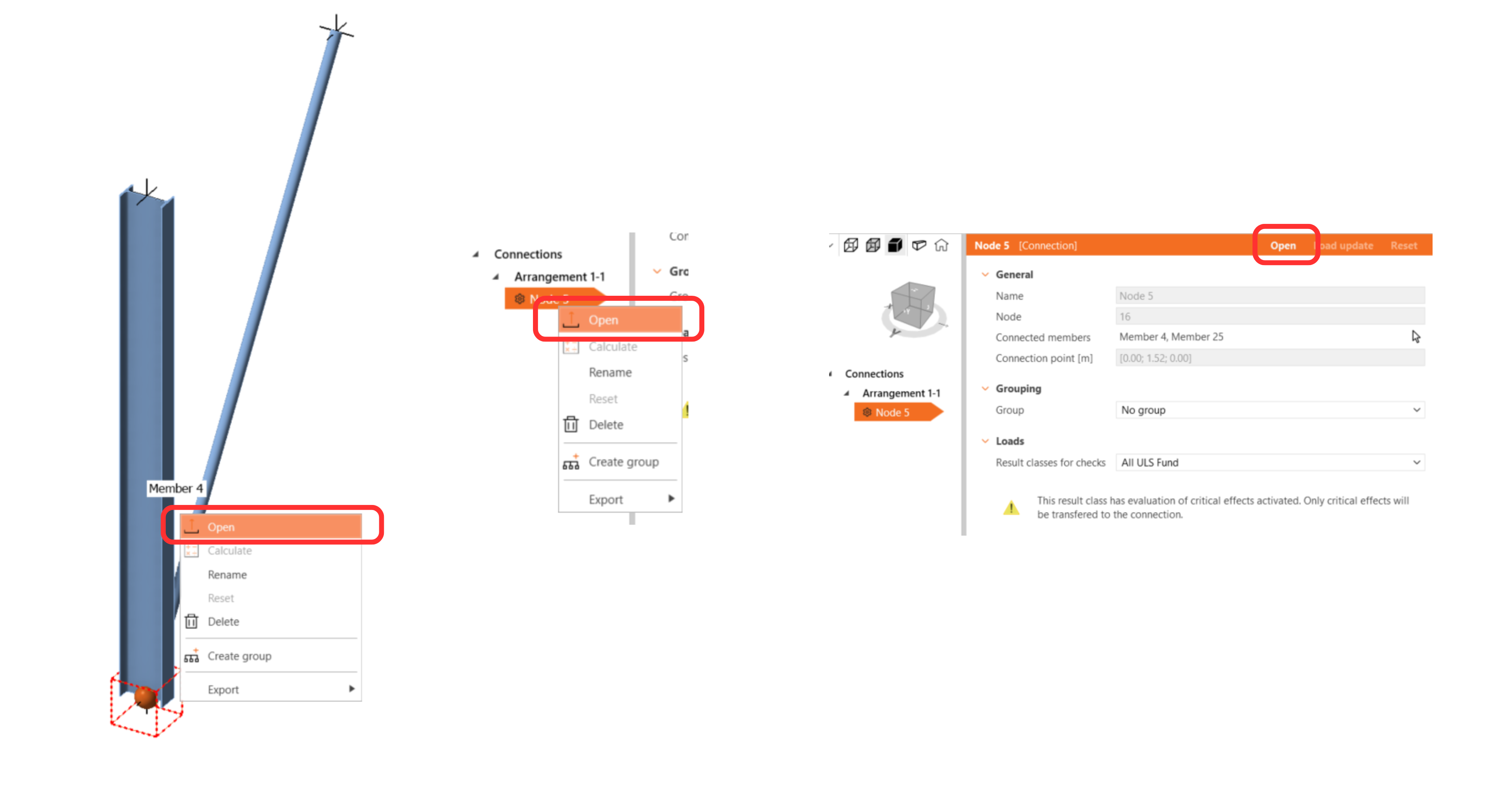
In the list of project items under Connections and with a connection highlighted in Checkbot you can either right-mouse click and select Open or click the ribbon command Open to start designing, code-checking, and reporting.
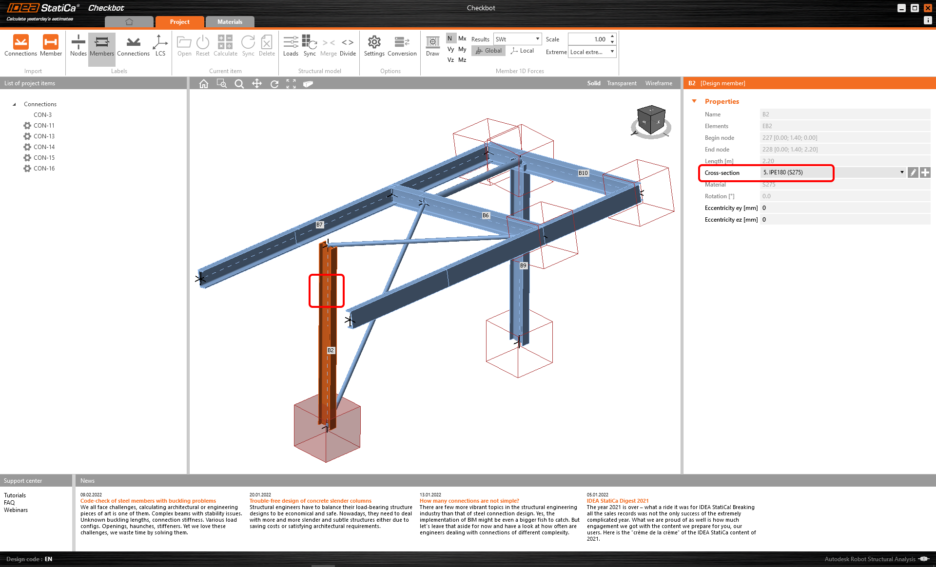
The settings of members are taken from the original FEA/BIM application. You can, however, change the section size of any member on the main Checkbot screen, but this will break the link with FEA/BIM application in this session unless it's synchronized again.
The imported connection is opened in the IDEA StatiCa Connection application.

You may see none or different Load effects from your preferred FEA/BIM* solution depending on how the load case combinations have been defined. By default, IDEA StatiCa will choose the most critical for code-checking purposes. (* Some BIM solutions are not able to store the load case combination results)
For more information on Load effects see here.
Design
We are going to be using a single bolt connection for the diagonal brace. For this type of connection, we must also change the Model type of the brace member to N-Vy-Vz. Select the brace in the list of Members and modify the Model type in the drop-down list.

We are going to use the Connection Library to generate a connection. Select Propose and IDEA StatiCa will put forward possible solutions for the current geometry.
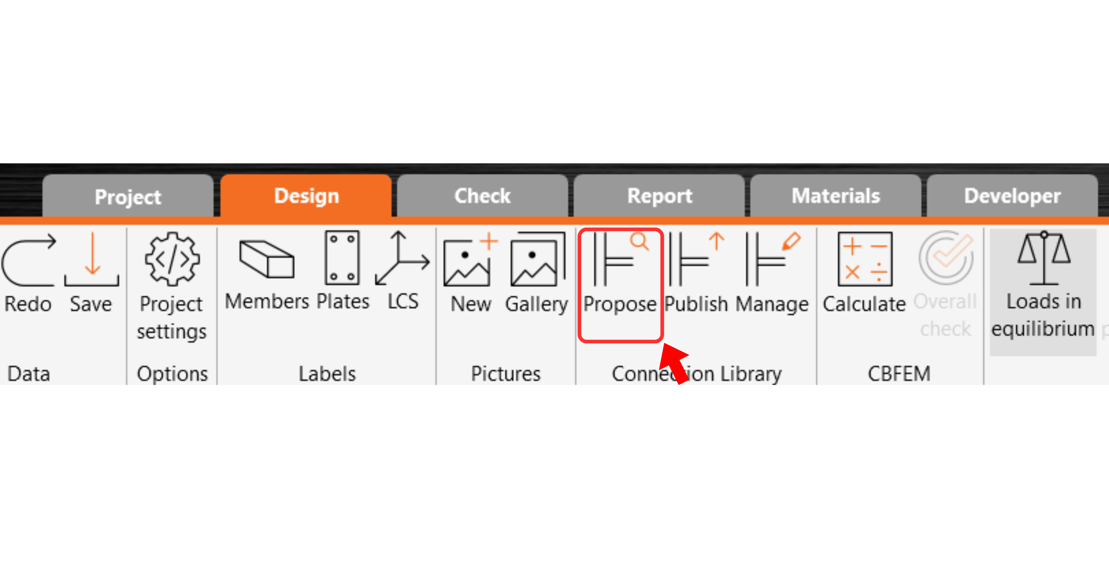
Connection Library shows you the possible solutions for the current geometry. Choose the template offered and press OK.

Accept the proposed values for the bolts and concrete block and press OK.

This is what the initial connection looks like.
With these default parameters for the Base plate.

These are the parameters for the Connecting plate.

That completes the design of the connection for the column base plate with a diagonal brace.
Code-check and Report
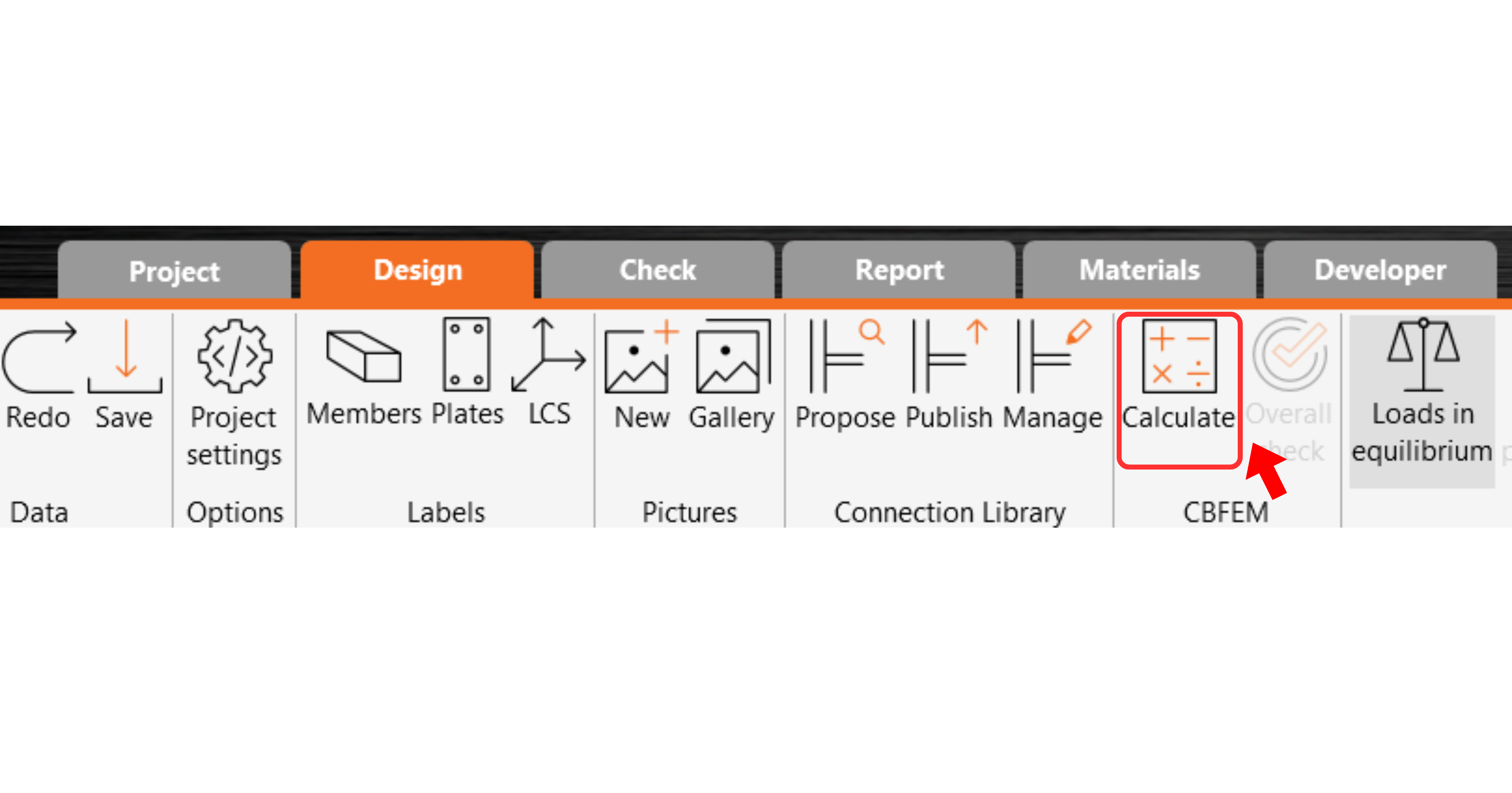
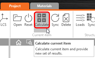
Now run a code-check using the Calculate icon in the CBFEM panel from the top ribbon.
Within IDEA StatiCa Connection, you can carry out many different types of analysis and code-checks. For more information, please see here.
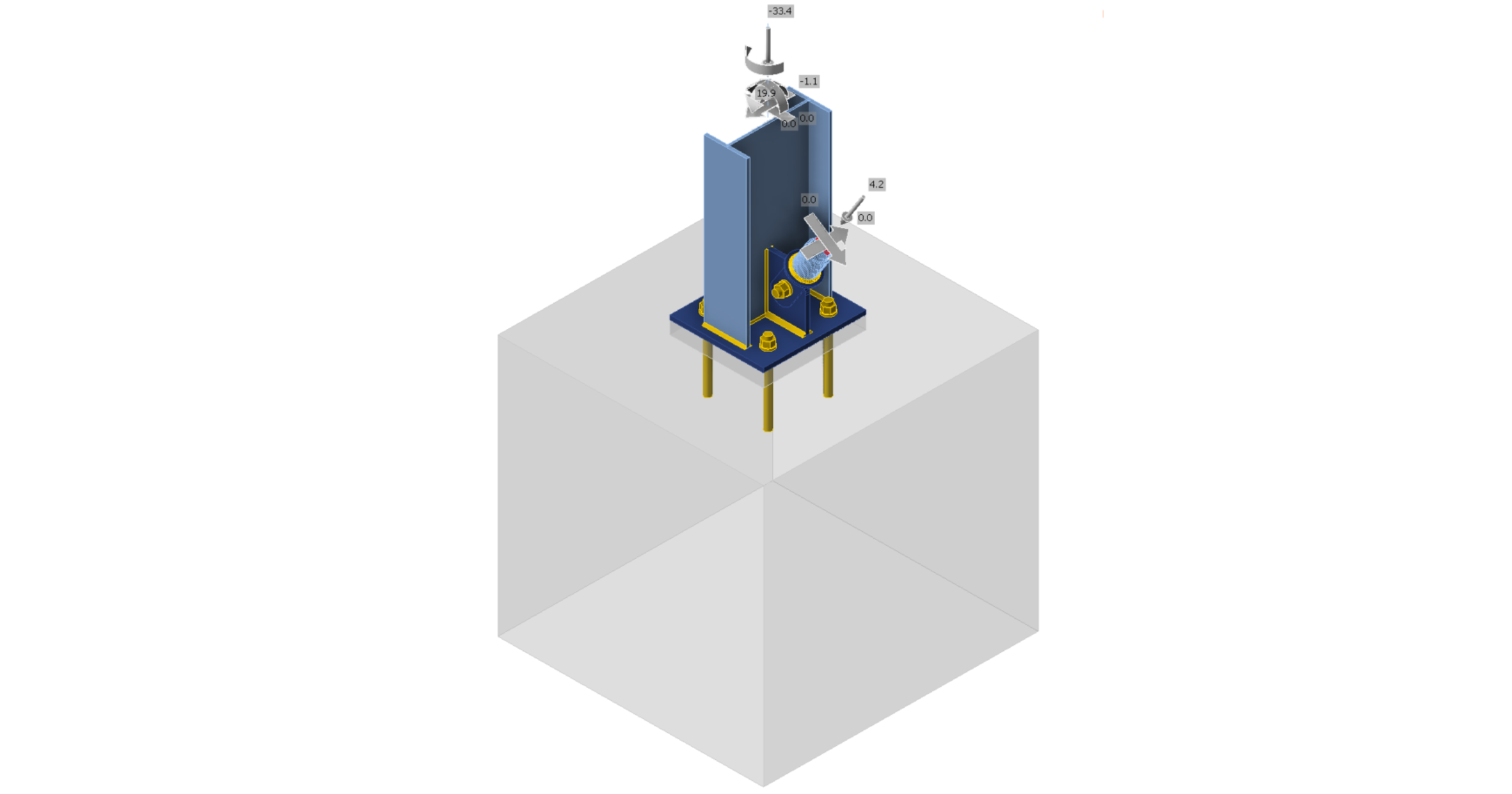
The results might not be acceptable. In this case, the anchors fail because of their low design capacity.

You can go to the Check tab to review the results and take a closer look at the anchors by expanding the calculation using the '+' symbol. You can see that the anchors are failing in tension in the concrete block.

We must optimize the design to find the passing solution. Go back to the Design tab, highlight the base plate operation, and change the Anchoring length to 200 mm and the concrete block Offset to 300 mm.

Run the analysis and code-check again.

Once the code-check is finished in the Report tab, you can create the report containing results and diagrams for your connection model.
The report can be printed or saved in several formats. For more information, please see here.

Save and Exit this connection back to Checkbot.
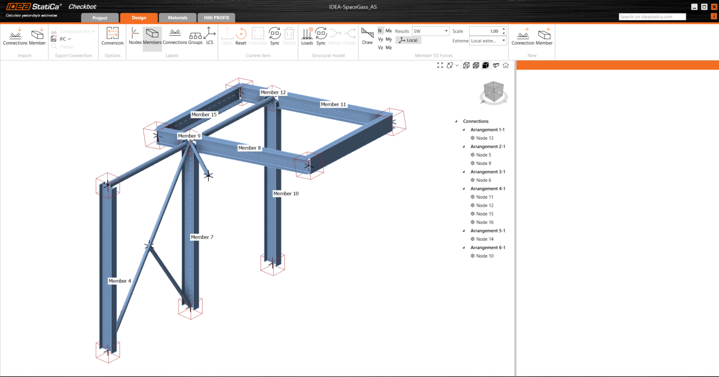
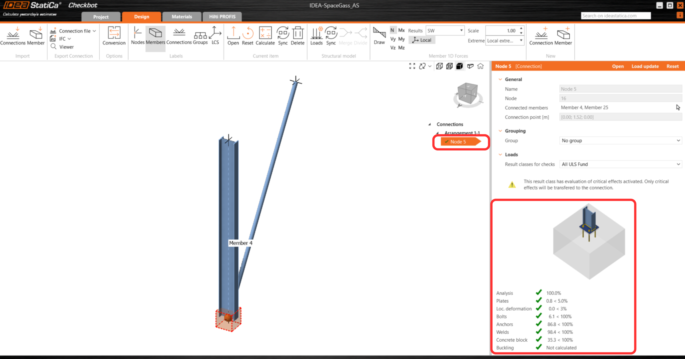
In Checkbot, you will see a green tick next to the connection. This means that the connection is valid and has passed all code-checks. In the Connection panel, you can also see a representation of the connection and a summary of the code-check results.
If multiple connections are present in Checkbot, then each must be opened, designed, and code-checked.
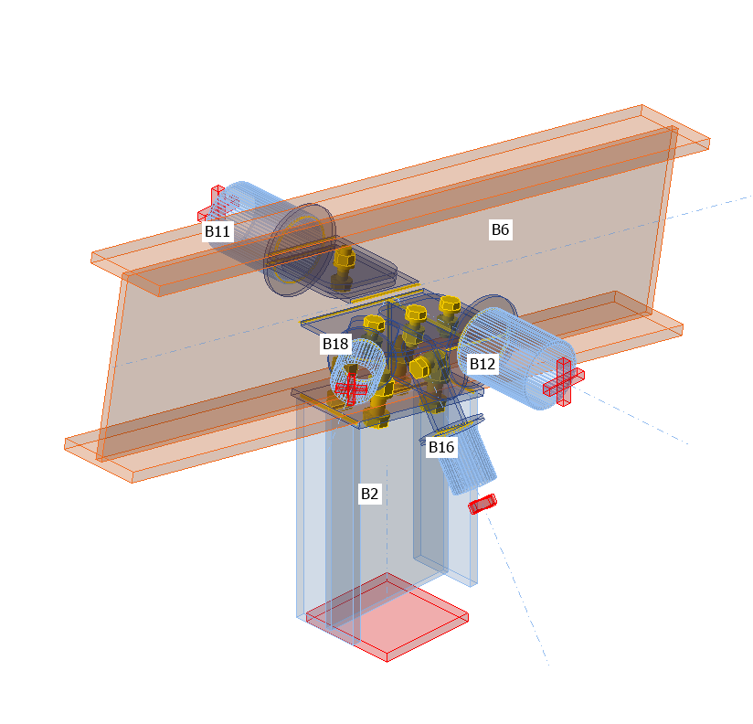
In the example below, you can see that baseplate connections have passed their respective code-checks whilst the remaining connections are yet to be validated.

You can continue with the design of additional connections - See how to model the roof connection with braces
Modell synchronisieren
Manchmal gibt es Änderungen an Ihrem FEA/BIM-Modell, wie z.B. unterschiedliche Querschnittsgrößen oder Lasten der Bauteile. Diese können zwischen Checkbot und dem FEA/BIM-Modell synchronisiert werden.
Es gibt zwei mögliche Alternativen:
- Aktuelle Position synchronisieren (wenn ein oder mehrere Anschlüsse ausgewählt sind)
- Gesamtes importiertes Strukturmodell synchronisieren
Um diese Funktion zu testen, können Sie die Größe oder Form eines Bauteilquerschnitts in Ihrer FEA/BIM-Anwendung ändern oder einen Lastfall oder eine Kombination ändern usw.: Ändern Sie die Stützen in einen kleineren Querschnitt. Denken Sie daran, das FEM-Modell erneut zu analysieren.
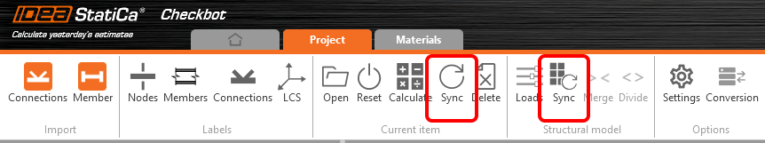
Wählen Sie in Checkbot die konstruierten Verbindungen aus (es kann mehr als eine geben) und wählen Sie im Bereich Aktuelle Position die Option Synchr..
Das Checkbot-Projekt wird aktualisiert, das Verbindungsdesign bleibt erhalten, aber die Ergebnisse werden ungültig. Sie können sehen, dass die Stütze jetzt aktualisiert wird – entsprechend der Änderung im FEM-Modell.
Überprüfen Sie die hervorgehobenen Verbindungen einfach erneut, indem Sie im Bereich Aktuelle Position die Option Berechnen auswählen. Bitte denken Sie daran, dass größere Änderungen im Modell möglicherweise zusätzliche Schritte zur Überprüfung mit den betroffenen Verbindungen erfordern (wie oben).
Wenn die Verbindungen nicht die gewünschten Ergebnisse liefern, können Sie sie erneut öffnen, um die Bemessung zu optimieren (d.h. verstärken, wenn sie den Nachweis nicht bestehen, oder reduzieren, wenn die Auslastung zu gering ist).
You have successfully linked Space Gass with IDEA StatiCa Connection via Checkbot.