Introduction
Bolts are commonly used as fasteners connecting steel elements in assembly joints. They facilitate the rapid construction of steel structures. Contractors typically require all connections at the construction site to be bolted; in other words, field welding should be avoided despite the fact that bolted connections may be much more complicated than welded connections and require more material.
The aim of this learning module is to make students familiar with and confident when designing simple bolted connections through interaction with connection design software providing visual feedback. Students should be familiar with the basics of design according to Eurocode – for more information, refer e.g. ESDEP lecture notes.
Example: Bolts in shear
Calculate the load on bolts and check the maximum loaded bolt.
Geometry
A plate with a thickness of 20 mm is connected to a cantilever consisting of two plates with a thickness of 8 mm each by two bolts M20 8.8. A cantilever is loaded by a force 50 kN at a distance 100 mm from the plate edge. Bolt holes are standard (\(d_0=22\textrm{ mm}\)) and the shear force passes through the threads.
Solution
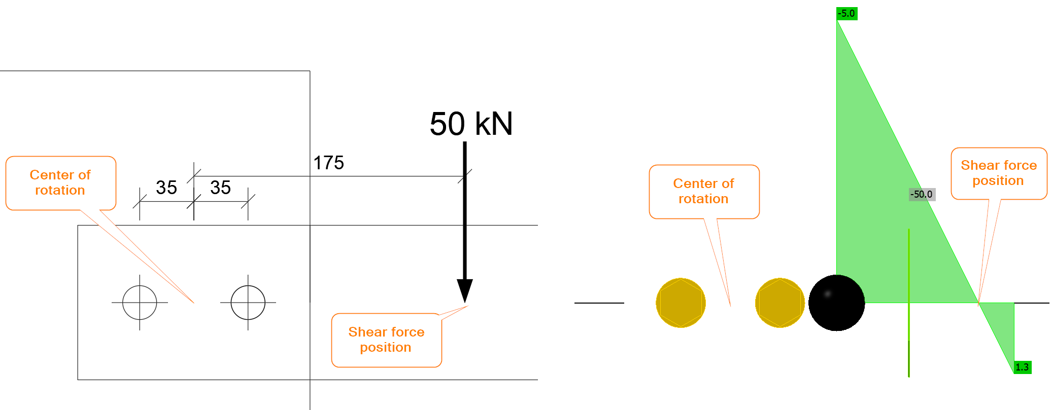
Crucial is the determination of the center of rotation and the loading on each bolt. The center of rotation for a bolt group loaded in shear is assumed to be in the center. The bolt connection is loaded by a shear force and bending moment. The shear force is \(V=50\textrm{ kN}\) and the bending moment is \(M=50\cdot 0.175=8.75 \textrm{kNm}\). In IDEA StatiCa, the shear force position must be correctly set or the connection loaded by a combination of shear force and bending moment.
The shear force is transferred via bolts uniformly, i.e. each bolt transfers the same portion of the shear load:
\[F_{1,V}=V_{Ed}/n_b=50/2=25\textrm{ kN}\]
where:
- \(V_{Ed}\) – set shear force
- \(n_b\) – number of bolts
In IDEA StatiCa, if the shear force position is set to Bolts, the bolt group is loaded purely by shear:
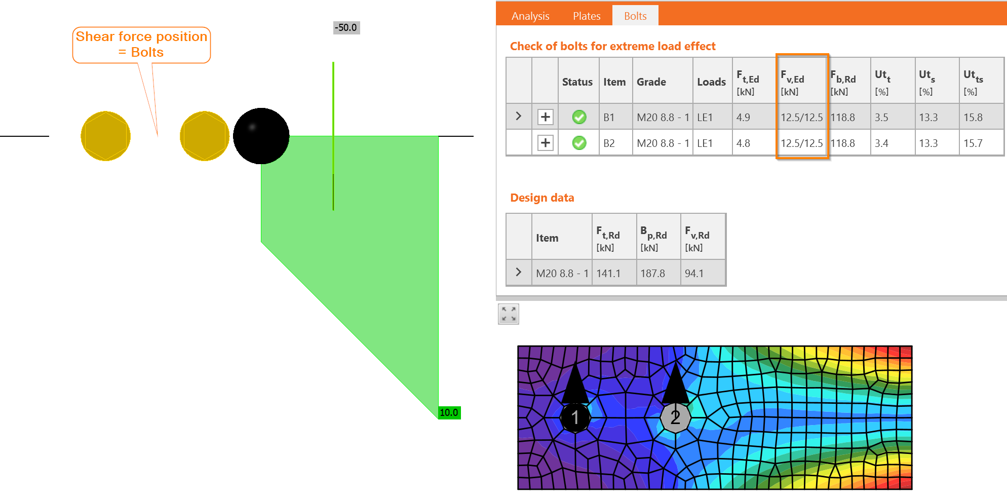
The forces are indeed identical and each bolt is loaded by 12.5/12.5, i.e. 12.5 kN in each shear plane.
The bending moment is transferred via the bolt group as well. Each bolt is loaded proportionally with the distance of the bolt to the center of rotation. In this example, there are only two bolts with identical distance:
\[r_i=p/2=70/2=35\textrm{ mm}\]
where:
- \(r_i\) – distance from bolt to the center of rotation
- \(p\) – bolt spacing
The force acting on each bolt, \(F_{1,M}\), is calculated:
\[F_{1,M}=M_{Ed}\frac{r_1}{\Sigma r_i^2}=8.75\frac{0.035}{0.035^2+0.035^2}=125\textrm{ kN}\]
where:
- \(M_{Ed}\) – bending moment acting on the connection
- \(r_1\) – distance from the investigated bolt to the center of rotation
- \(r_i\) – distance from each bolt to the center of rotation
Despite the point of application of the load being quite close, just 100 mm from the plate edge, the force in the bolt resulting from the bending moment is very large.
In IDEA StatiCa, the connection may be loaded only by bending moment:
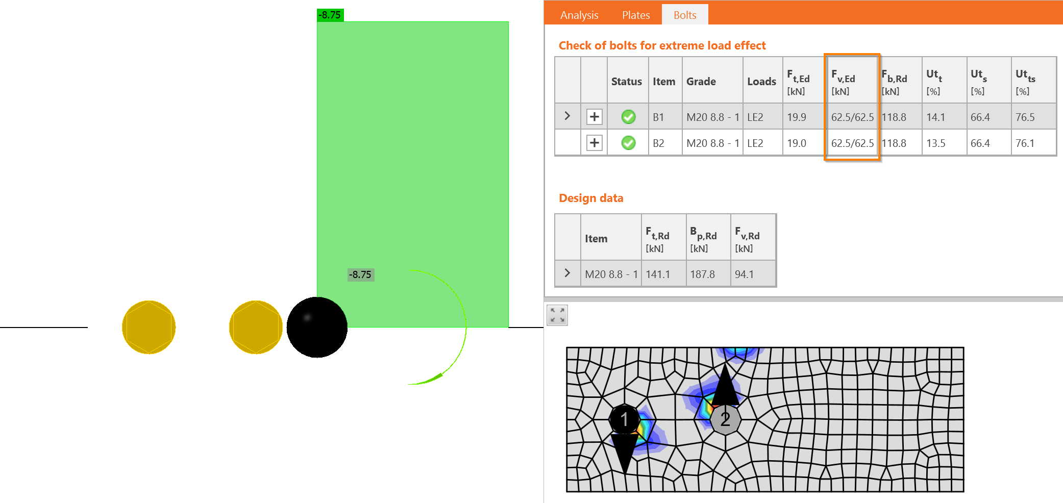
Now, we must do a vector sum of both effects – shear force and bending moment. The direction of forces is crucial here. The forces in bolts from shear force \(V_{Ed}\) acts downwards while the forces from bending moment rotate around the center of rotation. That means one goes upwards and the other downwards. The force in one bolt is subtracted: \(F_{1,v,Ed} = 25 - 125 = - 100\textrm{ kN}\), the force in the other bolt is summed: \(F_{2,v,Ed} = 25 + 125 = 150\textrm{ kN}\).
Exactly the same shear forces are in IDEA StatiCa.
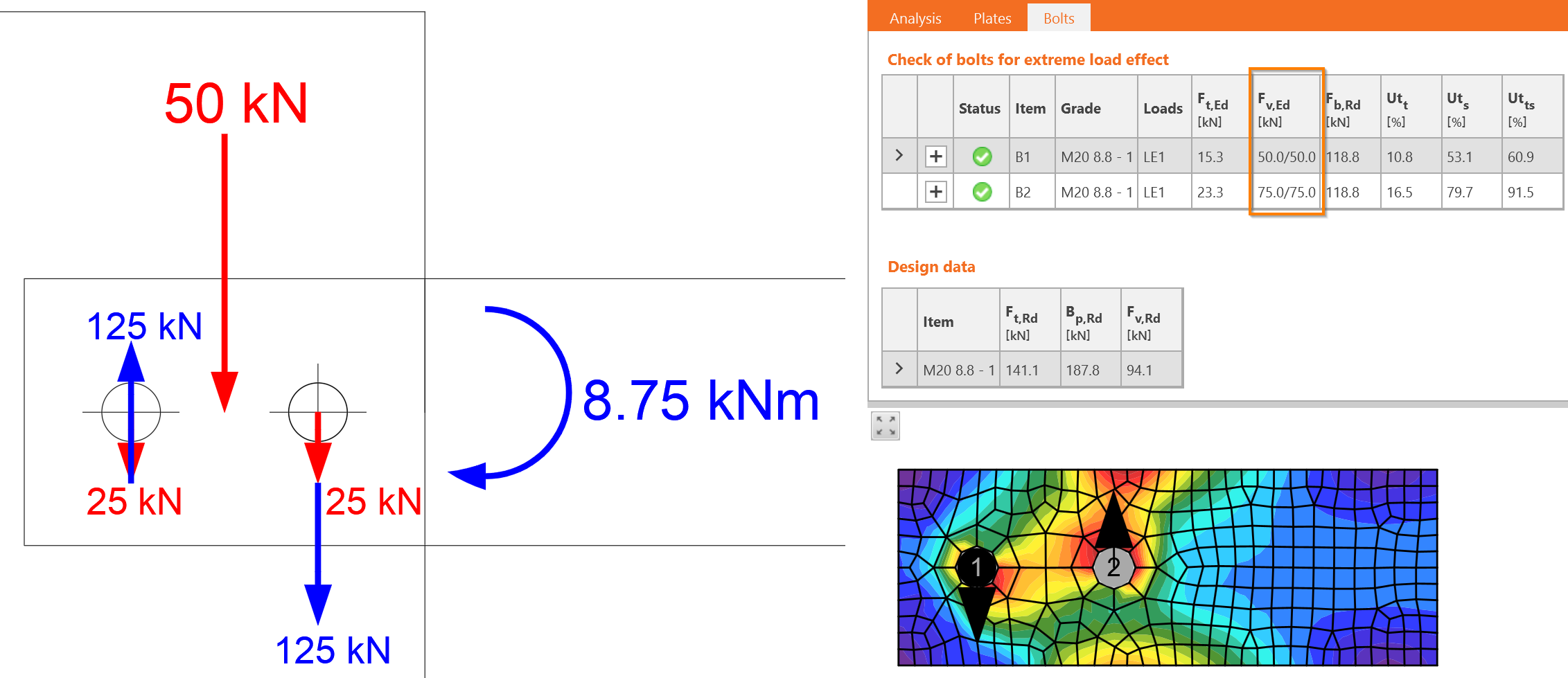
The bigger force determines the design, \(F_{v,Ed}=F_{2,v,Ed}=150\textrm{ kN}\).
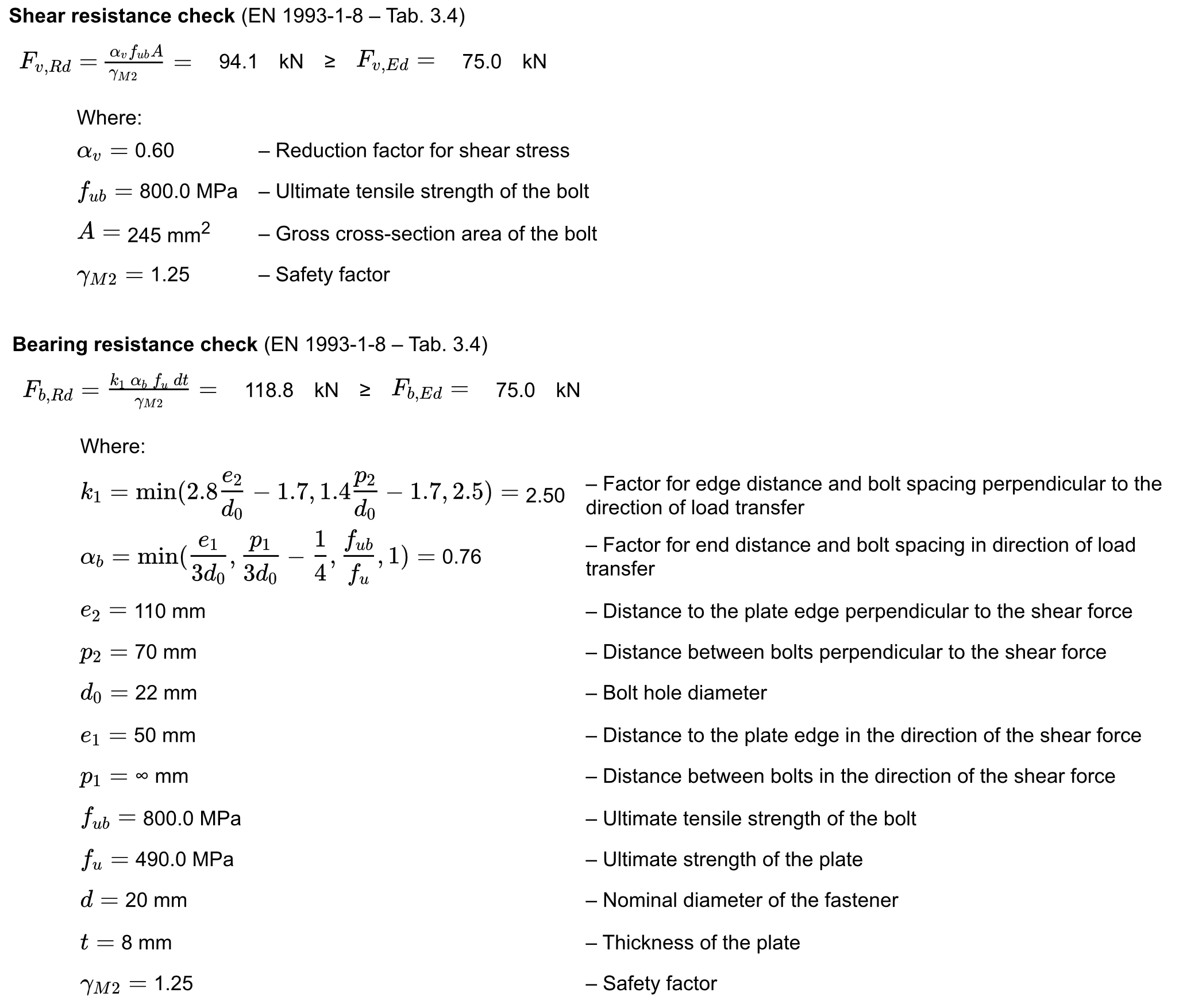
Detailed checks are provided for bolt B2. Bolts loaded in shear must be checked for:
- Shear resistance
- Bearing resistance
Virtual Lab – Bolts in Shear
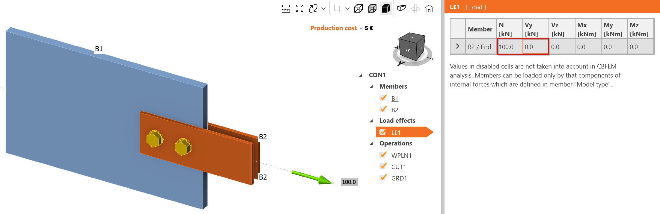
Change the load effect to tensile load only, 100 kN.
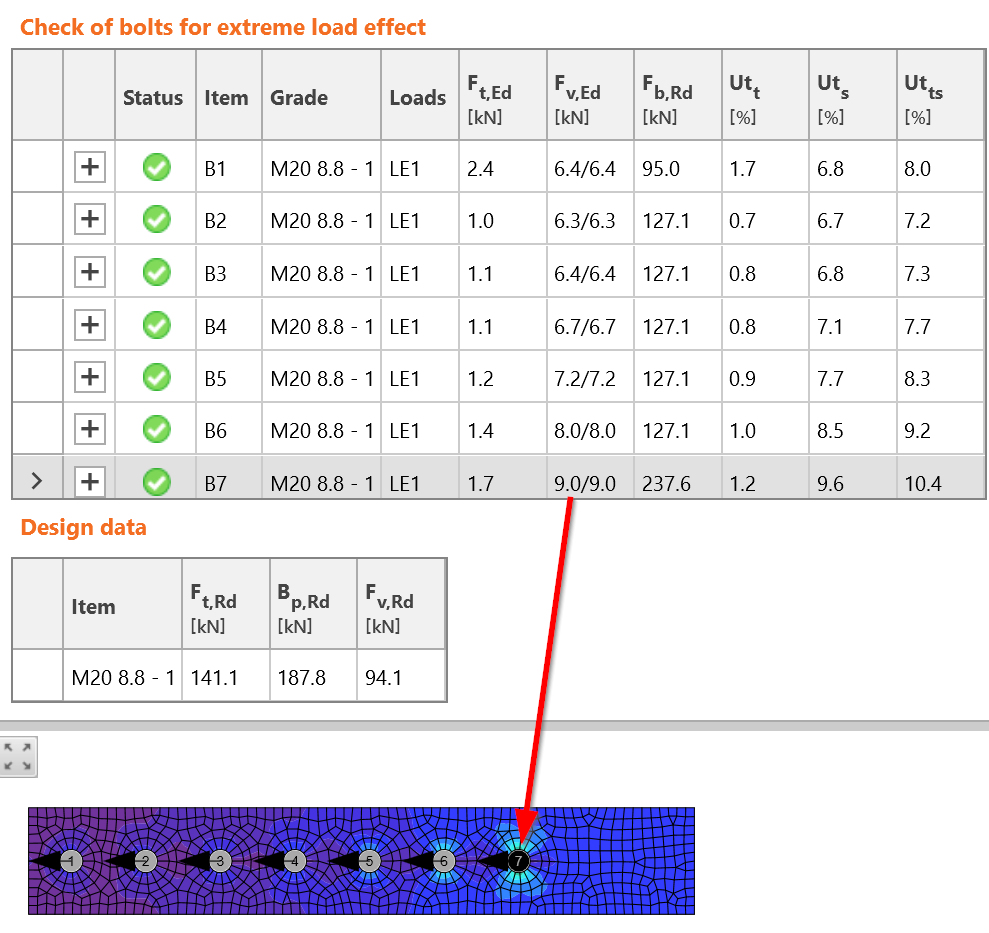
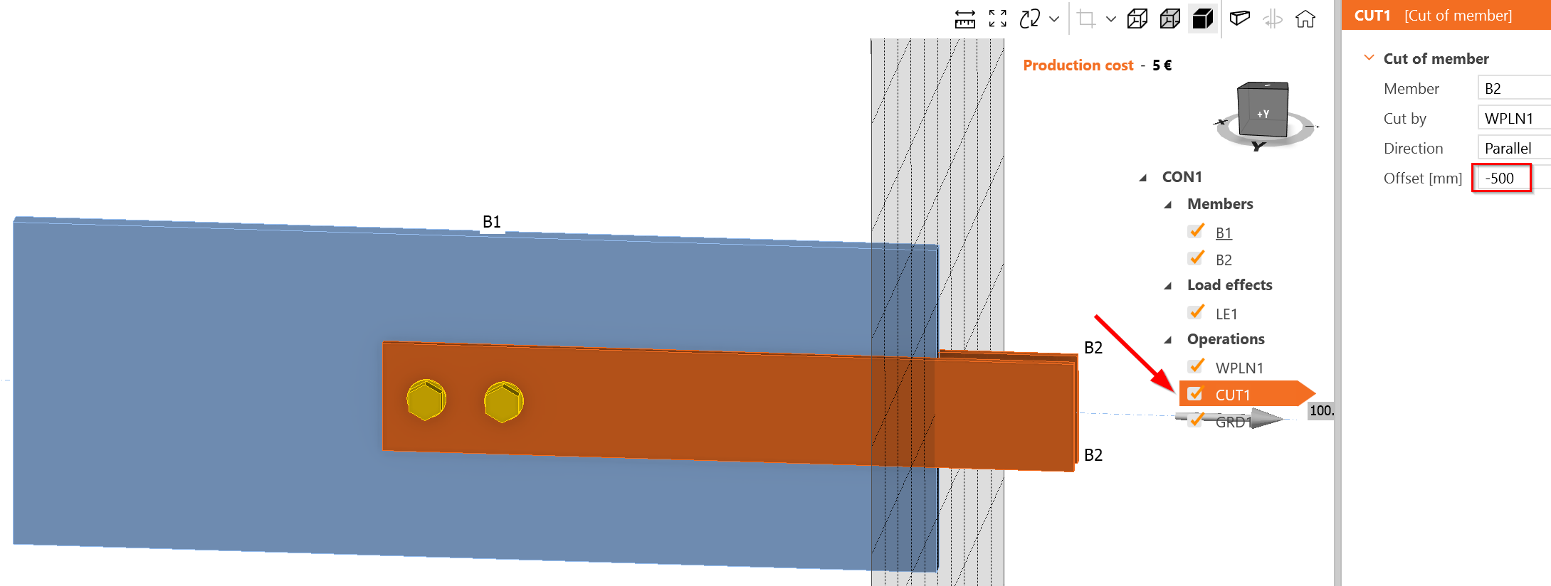
Create a long-bolted connection. Long bolted connection is longer than \(15\cdot d = 15\cdot 20 = 300\textrm{ mm}\). Extend the overlap of members:
Add more bolts with a spacing 70 mm:
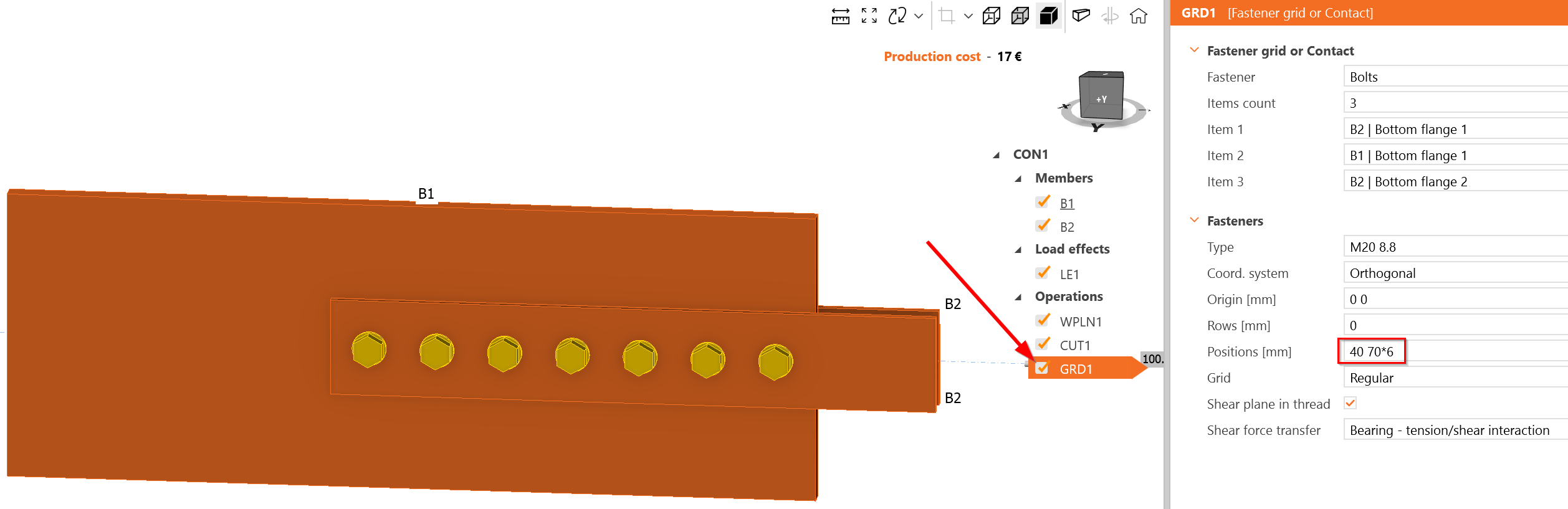
The most loaded bolt is B7, which is indeed located at the beginning of the bolt group. The load acting at each shear plane is 9 kN, i.e., 18 kN at bolt B7. This is more than the estimated 14.72 kN. It seems IDEA StatiCa provides a more conservative bolt force distribution; however, it may change with consecutive loading due to nonlinear calculation and nonlinear load-deformation diagram of the bolt in shear.