Column base – Open section column in bending to strong axis
Description
The object of this chapter is verification of component-based finite element method (CBFEM) of the column base of the steel open section column loaded in compression and bending around the stronger axis with the component method (CM). The study is prepared for size of the column, geometry, and thickness of base plate. In the study, five components are examined: column flange and web in compression, concrete in compression including grout, base plate in bending, anchors in tension, and welds. All components are designed according to EN 1993-1-8:2005, EN 1992‑1‑1:2005, and EN 1992‑4.
Verification of resistance
An example of component method design is shown on the anchorage of column steel section HEB 240:
Concrete block has dimensions a' = 1000 mm, b' = 1500 mm, h = 900 mm and grade C20/25. Base plate dimensions are a = 330 mm, b = 440 mm, t = 20 mm and steel grade is S235. Anchor bolts are 4 × M20, As = 245 mm2, length 300 mm, with head diameter a = 60 mm and steel grade 8.8. Grout thickness is 30 mm.
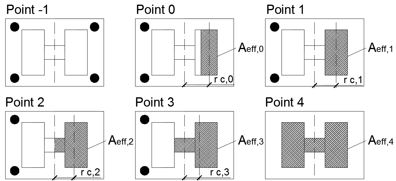
The results of the analytical solution may be presented on an interaction diagram with distinctive significant points. Point −1 represents loading in pure tension, and point 4 represents the compression bearing resistance. Detailed description of points 0, 1, 2, and 3 is shown in Fig. 8.2.1; see (Wald, 1995) and (Wald et al. 2008).
Fig. 8.2.1 Significant points on interaction diagram
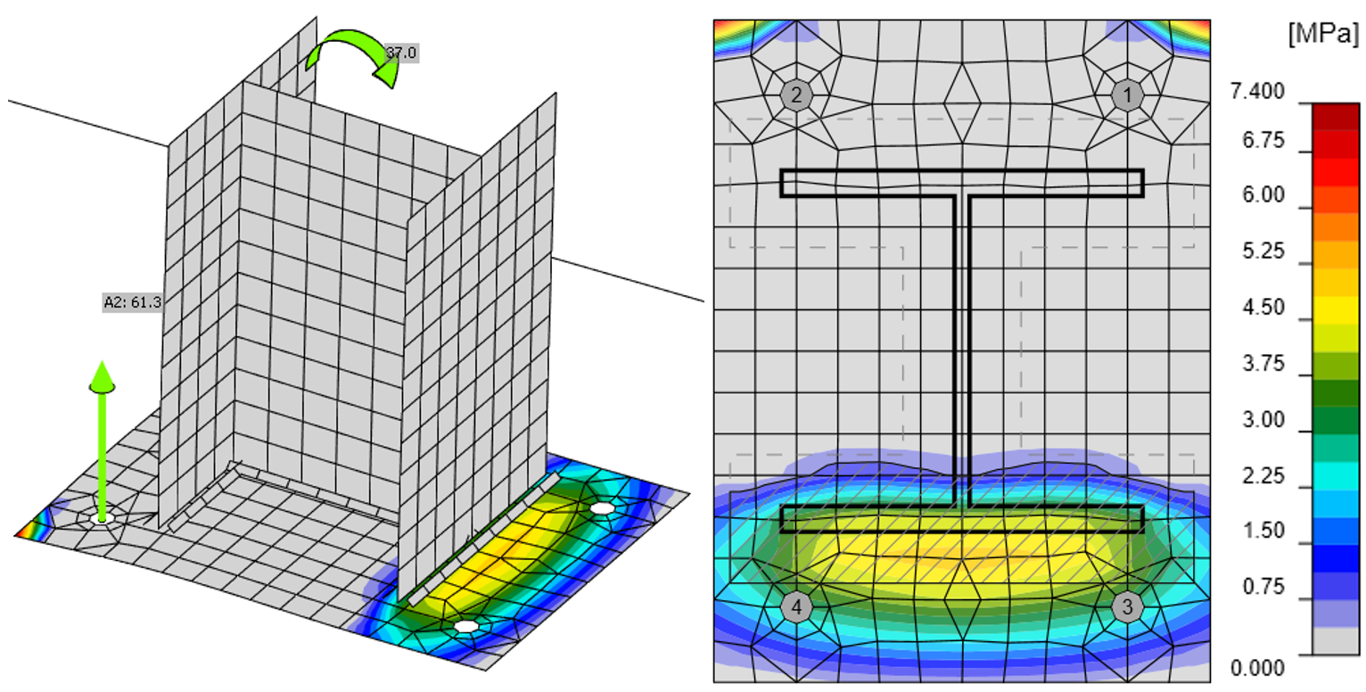
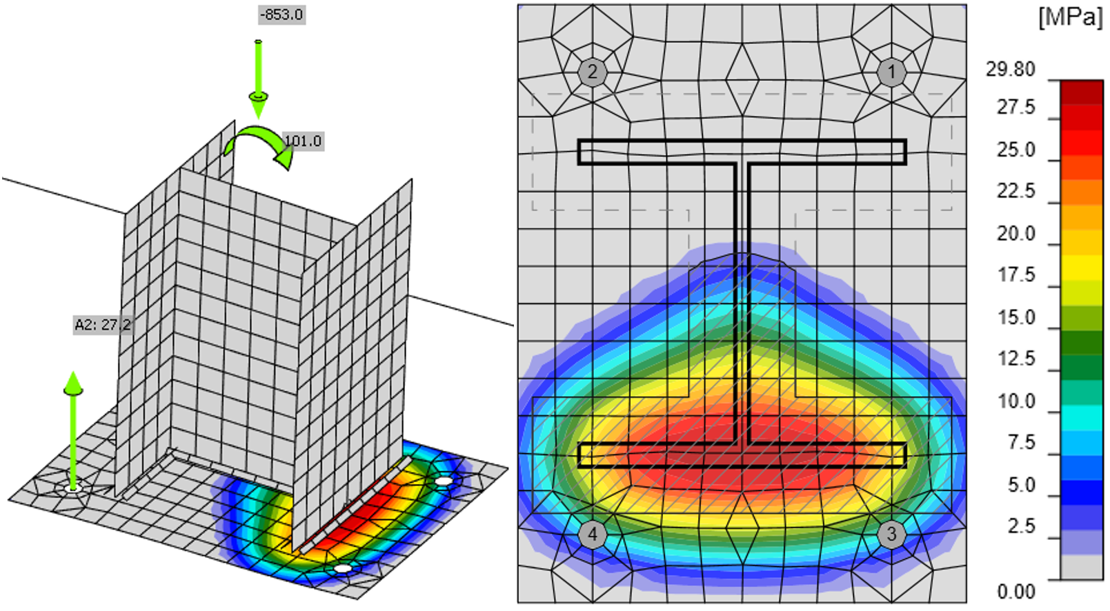
The stress distribution for point 0 and 3 reached by CBFEM is displayed in Fig. 8.2.2 and 8.2.3.
Fig. 8.2.2 Stress in concrete and forces in anchors for point 0 obtained by CBFEM (deform. scale 10)
Fig. 8.2.3 Stress in concrete and forces in anchors for point 3 obtained by CBFEM
(deform. scale 10)
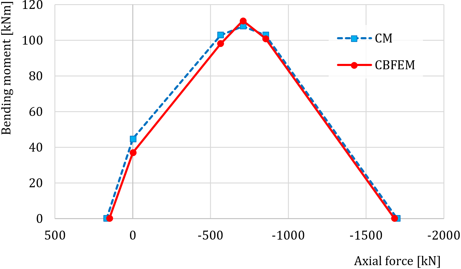
Fig. 8.2.4 Comparison of models on interaction diagram
The comparison of interaction diagram obtained by CBFEM to interaction diagram calculated according to CM is presented in Fig. 8.2.4 and Tab. 8.2.1.
Tab. 8.2.1 Comparison of results of interaction diagram for HEB 240 by analytic solution and by CBFEM
| Analytical solution | Results of CBFEM | |||
| Axial force [kN] | Bending resistance [kNm] | Axial force [kN] | Bending resistance [kNm] | |
| Point -1 | 169 | 0 | 150 | 0 |
| Point 0 | 0 | 45 | 0 | 37 |
| Point 1 | −564 | 103 | −564 | 98 |
| Point 2 | −708 | 108 | −708 | 111 |
| Point 3 | −853 | 103 | −853 | 101 |
| Point 4 | −1700 | 0 | −1683 | 0 |
Sensitivity study
The results of CBFEM were compared with the results of the component method. The comparison was made by bending moment resistance for the given level of normal force for each of the interaction diagram points.
In the sensitivity study, size of the column, dimensions of the base plate, and dimensions of concrete pad were changed. The selected column cross-sections were HEB 200, HEB 300, and HEB 400. The base plate width and length was chosen 100 mm, 150 mm, and 200 mm larger than the column section; the base plate thickness was 15 mm, 20 mm, and 25 mm. The concrete pad was from grade C25/30. The concrete pad height was for all cases 900 mm, and width and length were 200 mm larger than the dimensions of the base plate. Anchor bolts were M20 grade 8.8 with an embedment depth of 300 mm. The parameters are summarized in Tab. 8.2.2. Welds were the same around the whole column section with sufficient throat thickness in order not to be the critical component. One parameter was changed while the others were held constant at the middle value.
Tab. 8.2.2 Selected parameters
| Column section | HEB 200 | HEB 300 | HEB 400 |
| Base plate offset | 100 mm | 150 mm | 200 mm |
| Base plate thickness | 15 mm | 20 mm | 25 mm |
In Fig. 8.2.5, results for changes in the column cross-section are presented. In Fig. 8.2.6 and Fig. 8.2.7, the base plate offset and the base plate thickness are varied, respectively.
Fig. 8.2.5 Column section variation
Fig. 8.2.6 Base plate offset variation – 100, 200, and 300 mm
Fig. 8.2.7 Base plate thickness variation – 15, 20, and 25 mm
Benchmark case
Input
Column cross-section
- HEB 240
- Steel S235
Base plate
- Thickness 20 mm
- Offsets top 100 mm, left 45 mm
- Steel S235
Anchor bolt
- M20 8.8
- Anchoring length 300 mm
- Anchor type: Washer plate - circular; size 40 mm
- Offsets top layers 50 mm, left layers −10 mm
- Shear plane in thread
- Welds both 8 mm
Foundation block
- Concrete C20/25
- Offset 335 mm and 530 mm
- Depth 900 mm
- Shear force transfer friction
- Grout thickness 30 mm
Loading
- Axial force N = −853 kN
- Bending moment My = 100 kNm
Output
- Anchor bolts 42,2 % (NEd,g = 51,7 kN ≤ NRdc = 122,4 kN - concrete core breakout for anchors A1 and A2)
- Concrete block 99,5 % (σ = 26,7 MPa ≤ fjd = 26,8 MPa)
References
EN 1992-1-1, Eurocode 2, Design of concrete structures – Part 1-1: General rules and rules for buildings, CEN, Brussels, 2005.
EN 1992-4:2018, Eurocode 2: Design of concrete structures – Part 4: Design of fastenings for use in concrete, Brussels, 2018.
EN 1993-1-8, Eurocode 3, Design of steel structures – Part 1-8: Design of joints, CEN, Brussels, 2005.
Wald F. Column Bases, CTU Publishing House, Prague, 1995.
Wald F., Sokol Z., Steenhuis M., Jaspart, J.P. Component method for steel column bases, Heron, 53, 2008, 3-20.


