Fillet weld in angle plate joint
Description
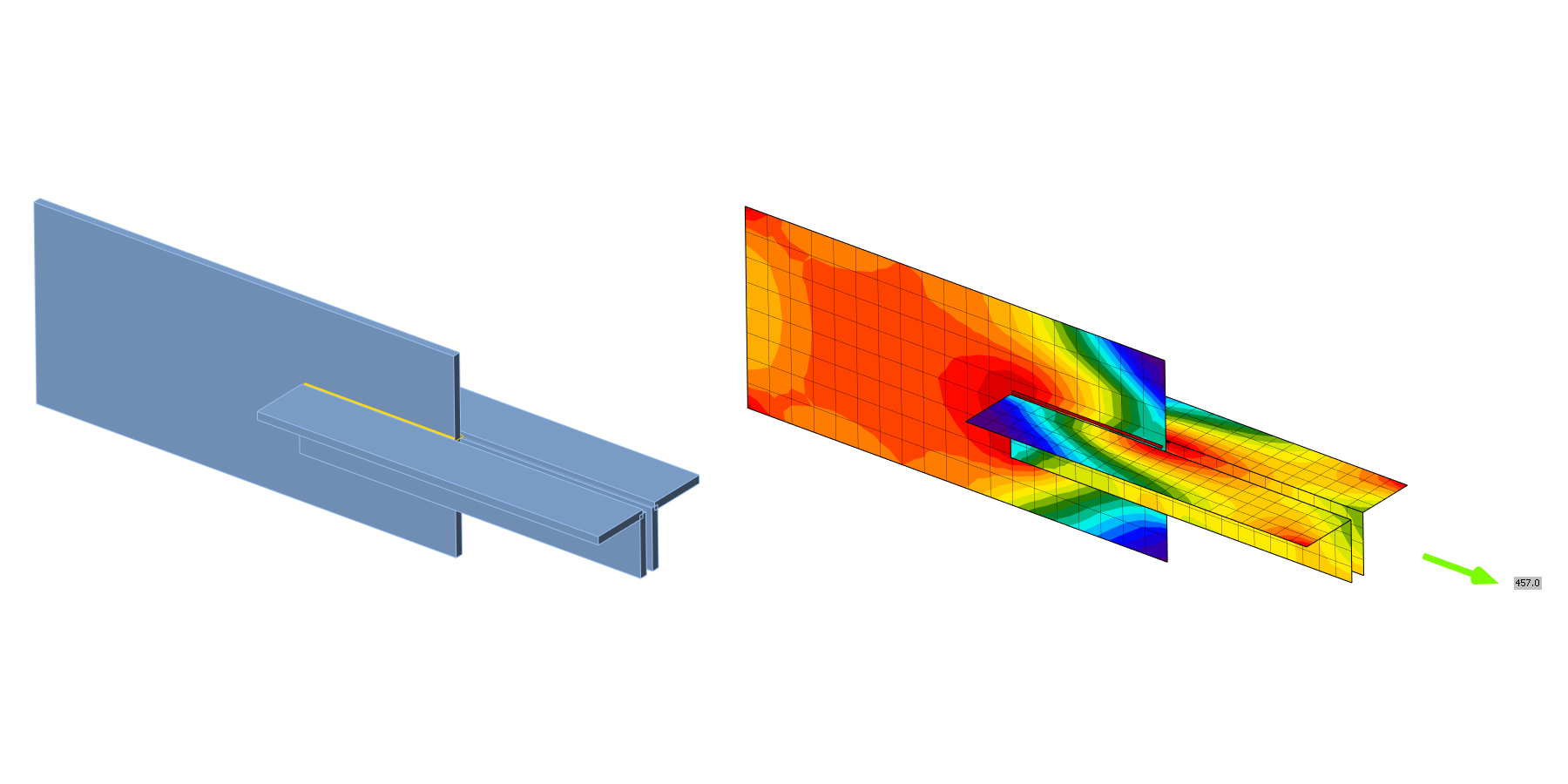
In this chapter, the model of the fillet weld in angle plate joint calculated by component-based finite element method (CBFEM) is verified on component method (CM). An angle is welded to a plate and loaded by normal force. The angle size and the length of the weld are studied in a sensitivity study.
Analytical model
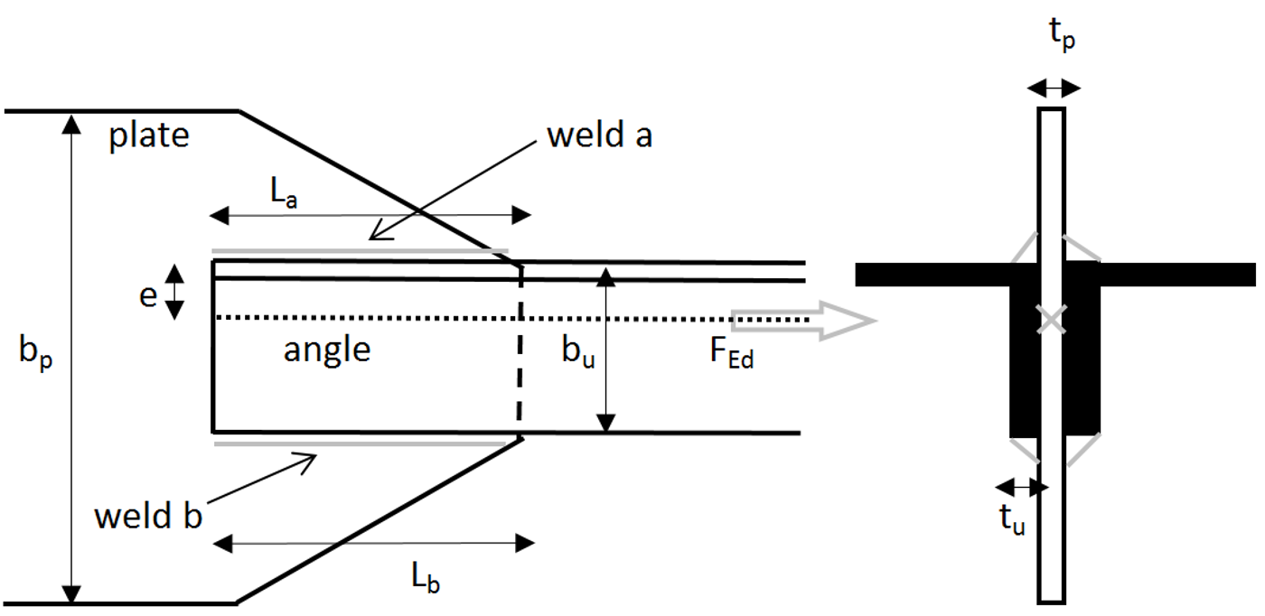
The fillet weld is the only component examined in the study. The welds are designed according to Chapter 4 in EN 1993-1-8:2005 to be the weakest component in the joint. The design resistance of the fillet weld is described in section 4.1. Overview of considered examples and material is given in Tab. 4.2.1. The geometry of the joints with dimensions is shown in Fig. 4.2.1.
Tab. 4.2.1 Examples overview
| Example | Material | Weld a | Weld b | Angle | Plate | |||||||
| fy | fu | E | γM0 | γM2 | aa | La | ab | Lb | section | bp | tp | |
| [MPa] | [MPa] | [GPa] | [-] | [-] | [mm] | [mm] | [mm] | [mm] | [-] | [mm] | [mm] | |
| 50×L80×10 | 235 | 360 | 210 | 1 | 1,25 | 3 | 50 | 3 | 50 | 80×10 | 240 | 10 |
| 100×L80×10 | 235 | 360 | 210 | 1 | 1,25 | 3 | 100 | 3 | 100 | 80×10 | 240 | 10 |
| 150×L80×10 | 235 | 360 | 210 | 1 | 1,25 | 3 | 150 | 3 | 150 | 80×10 | 240 | 10 |
| 200×L80×10 | 235 | 360 | 210 | 1 | 1,25 | 3 | 200 | 3 | 200 | 80×10 | 240 | 10 |
| 100×L160×16 | 235 | 360 | 210 | 1 | 1,25 | 5 | 100 | 3 | 100 | 160×16 | 400 | 16 |
| 170×L160×16 | 235 | 360 | 210 | 1 | 1,25 | 5 | 170 | 3 | 170 | 160×16 | 400 | 16 |
| 240×L160×16 | 235 | 360 | 210 | 1 | 1,25 | 5 | 240 | 3 | 240 | 160×16 | 400 | 16 |
| 310×L160×16 | 235 | 360 | 210 | 1 | 1,25 | 5 | 310 | 3 | 310 | 160×16 | 400 | 16 |
| 380×L160×16 | 235 | 360 | 210 | 1 | 1,25 | 5 | 380 | 3 | 380 | 160×16 | 400 | 16 |
| 450×L160×16 | 235 | 360 | 210 | 1 | 1,25 | 5 | 450 | 3 | 450 | 160×16 | 400 | 16 |
Fig. 4.2.1 Joint geometry with dimensions
Numerical model
The model of the weld in CBFEM is described in section 3.4. The weld model has an elastic-plastic material diagram, and stress peaks are redistributed along the weld length.
Verification of resistance
The weld design resistances calculated by CBFEM are compared with the results of CM; see Tab. 4.2.2. Two parameters are studied: the length of the weld and the angle section.
Tab. 4.2.2 Comparison of CBFEM and CM
| Example | Design resistance | Example | Design resistance | |||||
| CM | CBFEM | diff. | CM | CBFEM | diff. | |||
| [kN] | [kN] | [%] | [kN] | [kN] | [%] | |||
| 50×L80×10 | 124 | 120 | -3 | 100×L160×16 | 332 | 328 | -1 | |
| 100×L80×10 | 249 | 235 | -6 | 170×L160×16 | 565 | 555 | -2 | |
| 150×L80×10 | 374 | 350 | -7 | 240×L160×16 | 798 | 773 | -3 | |
| 200×L80×10 | 498 | 457 | -9 | 310×L160×16 | 1030 | 988 | -4 | |
| 380×L160×16 | 1263 | 1206 | -5 | |||||
| 450×L160×16 | 1496 | 1419 | -5 |
Fig. 4.2.2 Sensitivity study of weld length
Results of CBFEM and CM are compared, and the sensitivity study is presented. The influence of weld length on the design resistance of a welded angle joint is shown in Fig. 4.2.2. The study shows good agreement for all weld configurations. To illustrate the accuracy of the CBFEM model, the results of the study are summarized in a diagram comparing design resistances by CBFEM and CM; see Fig. 4.2.3. The results show that the difference between the two calculation methods is in all cases less than 10 %.
Fig. 4.2.3 Verification of CBFEM to CM
Benchmark example
Inputs
Angle
- Cross-section 2×L80×10
- Distance between angles 10 mm
Plate
- Thickness tp = 10 mm
- Width bp = 240 mm
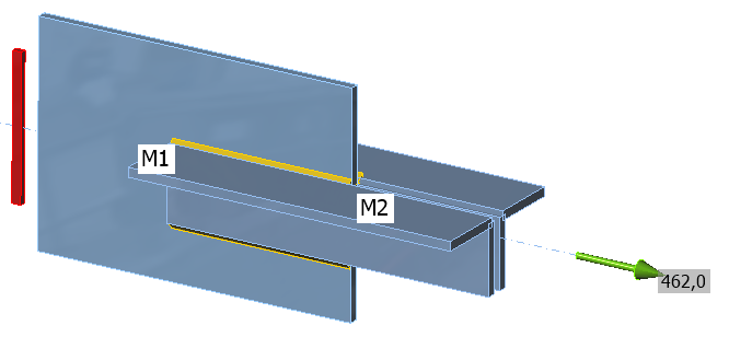
Weld, parallel fillet welds, see Fig. 4.2.4
- Throat thickness aw = 3 mm
- Weld length Lw = 200 mm
Outputs
- Design resistance in tension FRd = 457 kN
Fig. 4.2.4 Benchmark example of the welded angle plate joint with parallel fillet welds


