General anchoring shapes and options
How to model steel-to-concrete connection
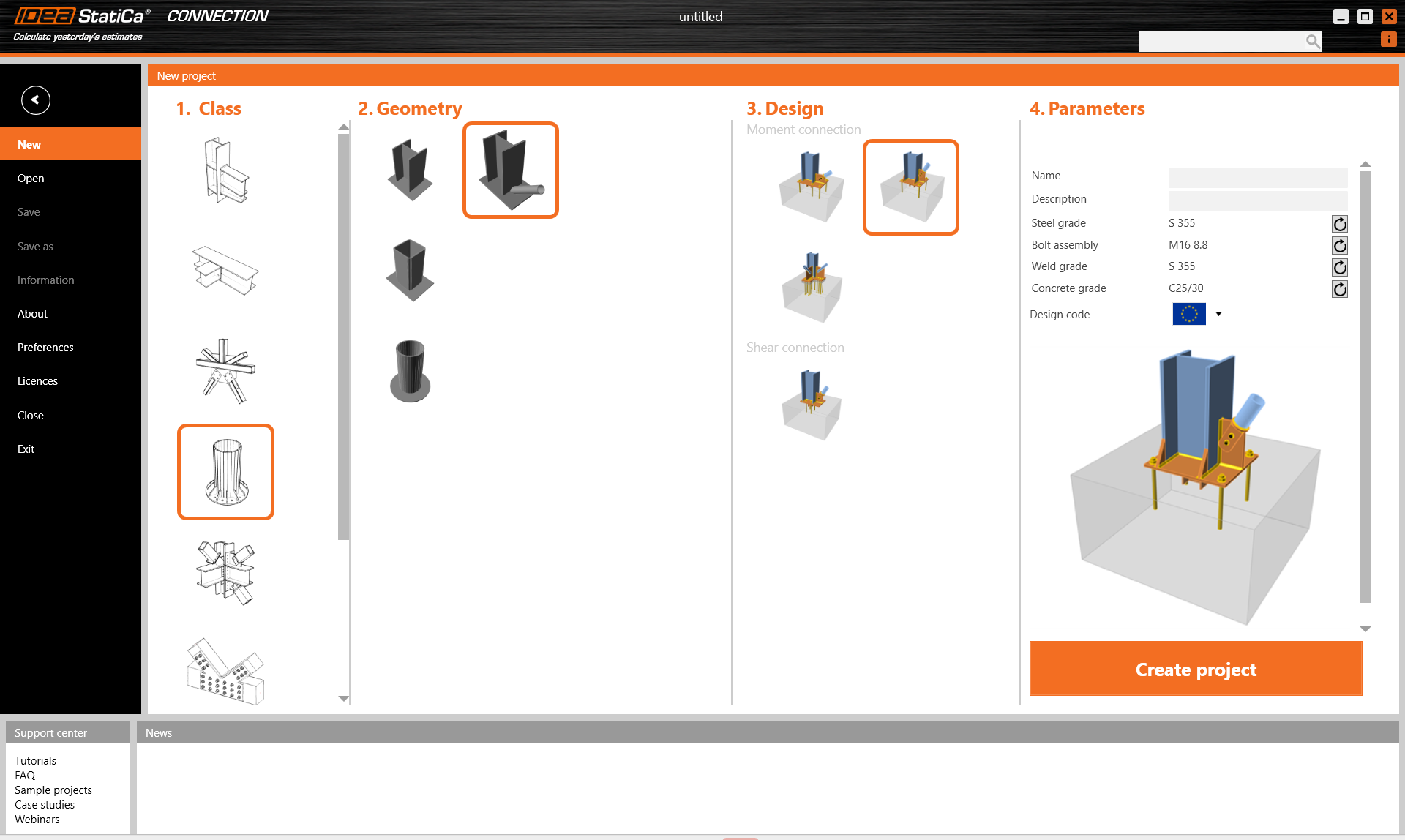
The first option is modeling the anchoring using our connection wizard offering options of moment and shear connection, footings with or without bracing.
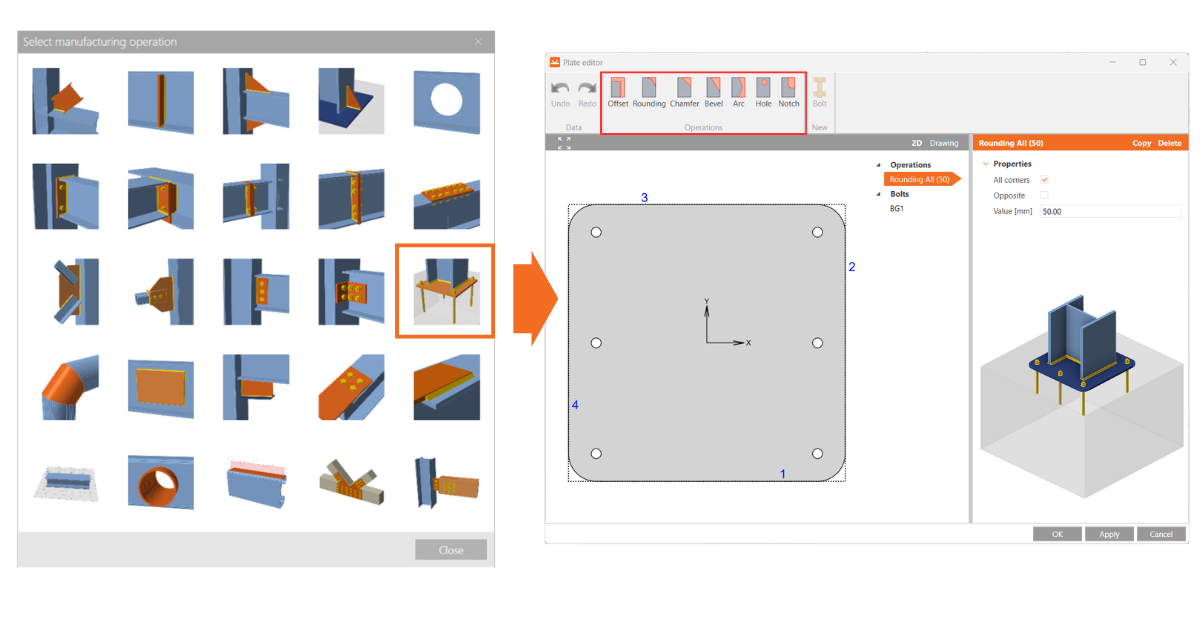
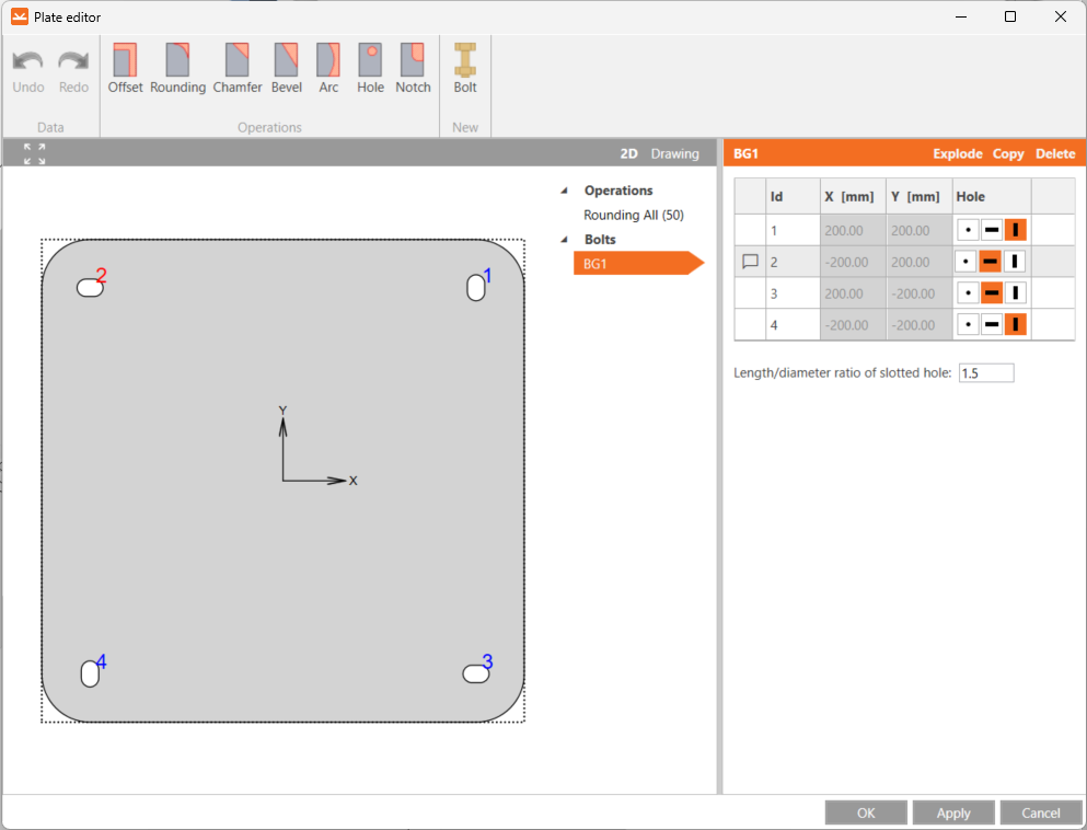
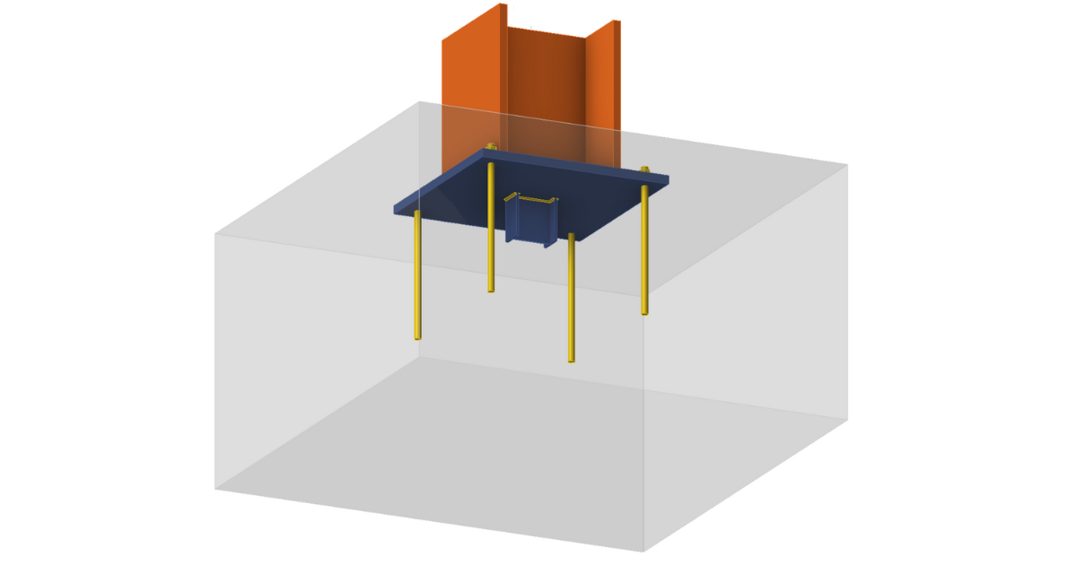
The second approach for modeling a footing is through the Base Plate operation. This approach is specifically intended for scenarios where the base plate is perpendicular to the anchored member. When using this operation, anchors are generated automatically. Additionally, the shape of the base plate can be customized in the Editor, allowing modifications such as creating base plates with round edges to suit specific design needs and specifying slotted holes for anchors.
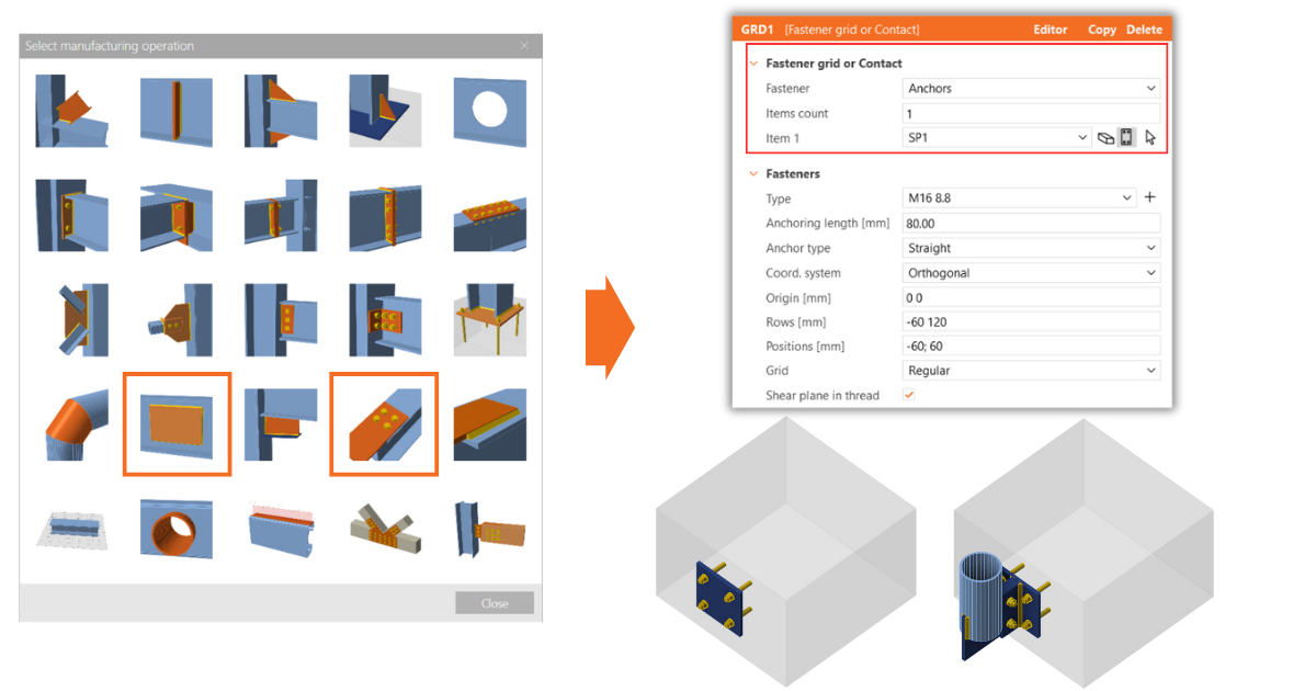
For situations where the base plate is not perpendicular to the anchored member, the modeling process requires a different approach. In these cases, you must use the Stiffening plate operation to model the base plate and the Fastener grid or Contact operation to define the anchors. The stiffening plate is positioned in the required angle and location, and the fastener grid must be adjusted to the Anchor type. Then the number of connected items is changed to one and the the stiffening plate is defined as the selected item.
In cases when the connection is already modeled in CAD software, you can import anchoring design using BIM links.
Example of general anchoring using the stiffening plate
Watch the recording to learn how to design a custom vertical base plate of balcony railing into a concrete slab.
Concrete block
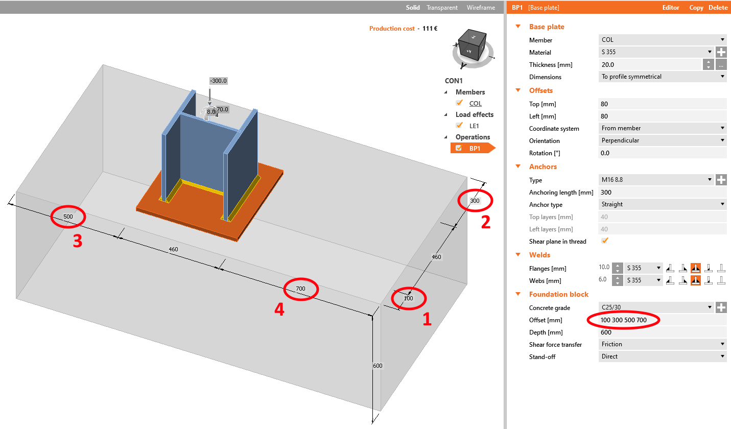
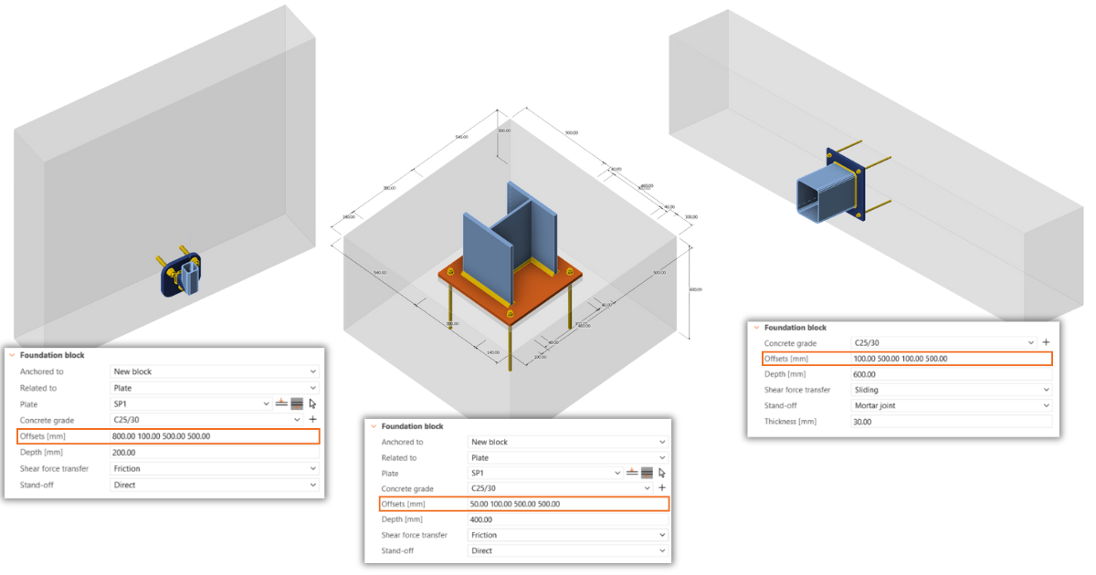
The concrete foundation is limited to a rectangular shape, but its dimensions can be adjusted using offset values for each edge. Entering a single value creates a uniform offset around the anchored cross-section outline. Inputting two values applies symmetrical offsets in two directions. Providing four values applies offsets to each edge individually to easily achieve asymmetrical anchoring.
Offset operation allows you to create a rectangular concrete block, a foundation belt, a concrete wall, a beam, a column, a ceiling, or an inclined member.
You can also create a partially supported base plate by entering different offset values. For instance, this allows a steel beam to rest on a concrete block with only part of its flange in contact.
Negative values can also be entered for the concrete block offset to create a block smaller than the base plate or the anchored plate of the member.
Anchor types
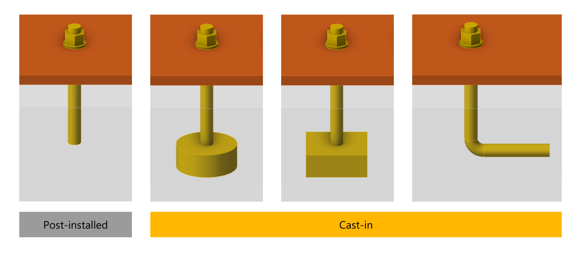
Various types of anchor bolts can be designed in IDEA StatiCa. You can select from straight anchors, headed anchors (circular or rectangular washer plates), and hooked anchor bolts. The length, diameter, and material of the fasteners can be modified.
Straight anchors are automatically assumed post-installed, and anchors with washer plates and hooks are considered cast-in, which differentiates required code-checks.
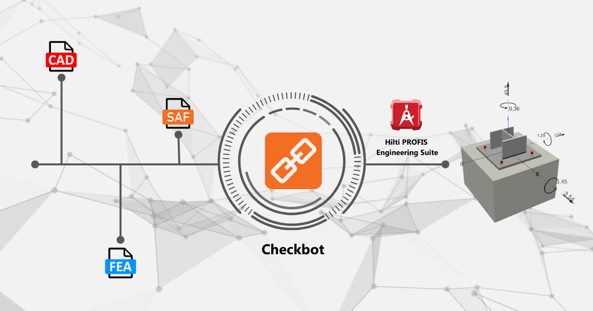
To design anchors from Hilti's hardware you can use Hilti PROFIS plugin in Checkbot. This enables data transfer from supported third-party FEA and CAD software to Hilti PROFIS Engineering Suite via using free Checkbot. Learn how to use the Hilti PROFIS Engineering Suite plugin.
Shear transfer
There are three options for transferring the shear from the anchored member into the foundation block: friction, shear lug, or anchors. The shear transfer is always transmitted exclusively through one of the options, cannot be combined.
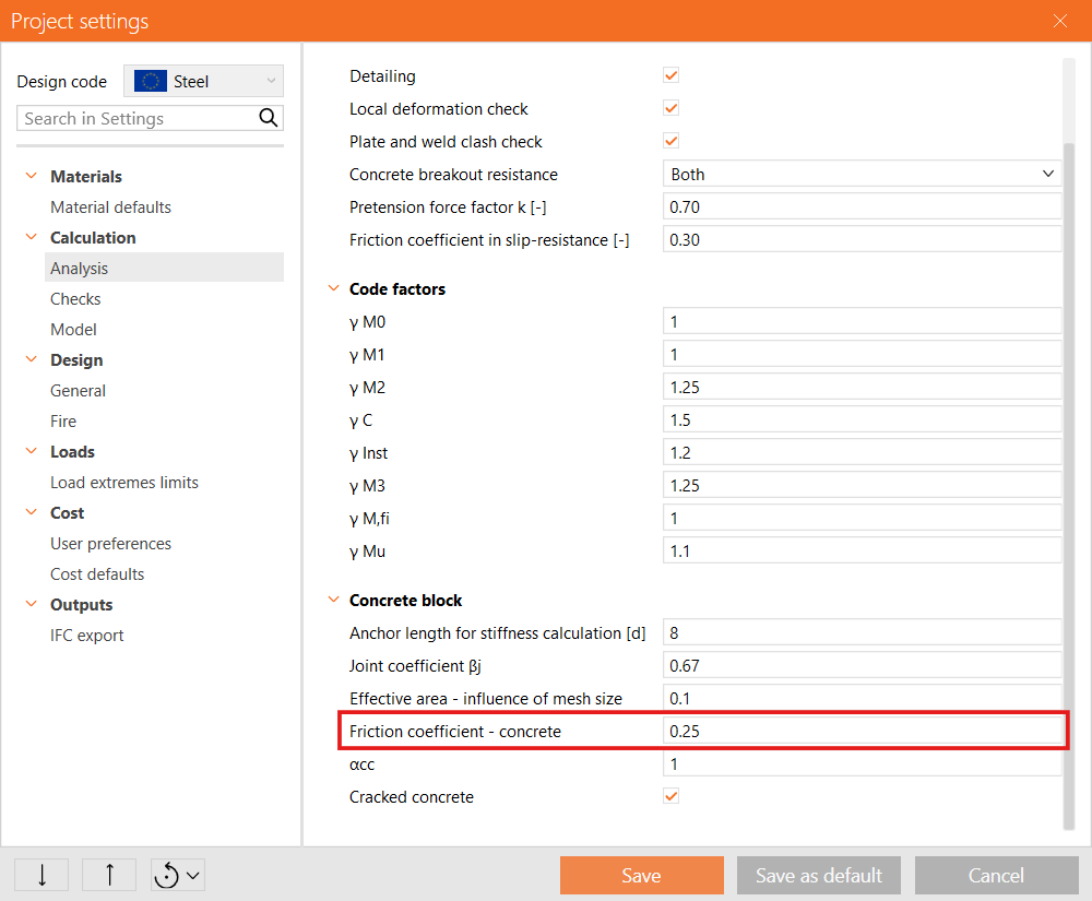
The default option is transferring shear via friction between the base plate and the grout layer represented by the friction coefficient which can be modified according to the type of grout in Project settings. Coefficient affects design friction resistance.
Another option of shear transfer is via shear lug. This element consists of a general steel member welded to the bottom of the base plate. The shear lug is defined via length, the steel embedment might be positioned exocentrically and also rotated. The code check of the shear lug is carried out by shear lug steel resistance and concrete bearing resistance.
Another option for transferring shear in the IDEA StatiCa Connection is via anchors.
The last option is Sliding representing a sliding hinge (roller) implemented only for analysis in IDEA StatiCa Member. For modeling only in Connection the option should not be used.
Stand-off
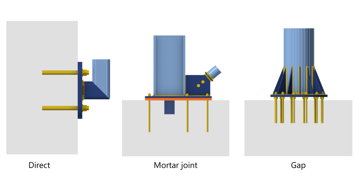
There are 3 ways to model the connection of a base plate with a foundation block. The first and also default option is a direct with no space between two elements. Another option is a mortar joint (grout) with adjustable thickness. In these cases, you have to be careful to set up the real value of a friction coefficient between the base plate, grout, and concrete footing in Project settings. The default value is 0,25. The last option is a gap to prevent direct contact between the base plate and the concrete block to avoid corrosion.
The forces are determined using finite element analysis. The bending moment of anchors with stand-off is dependent on the stiffness ratio of the anchors and base plate.
Stiffeners
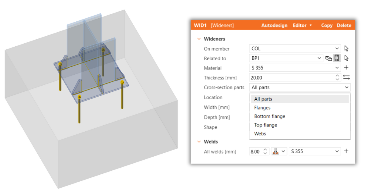
To provide additional strength, stiffeners can be added to the connected member. This can be achieved using the Rib operation which is suitable for cases when stiffeners are applied to a single plate (web/flange). Alternatively, the Widener operation allows you to assign stiffeners to multiple parts of cross-section.
Code-check anchors
Further details of the code-check of anchors can be found below:
- Code-check of anchors - Eurocode
- Code-check of anchors - AISC
- Code-check of anchors - Australian standards
- Code-check of anchors - Canadian standards
Not all code checks of anchors are performed in the IDEA StatiCa Connection application due to limitations arising from the configuration of the anchors.
Code-check of concrete blocks
Further details of the code-check of concrete block can be found below:
- Code-check of concrete blocks - Eurocode
- Code-check of concrete blocks - AISC
- Code-check of concrete block - Australian standards
- Code-check of concrete block - Canadian standards
Code-check cracked concrete or uncracked concrete
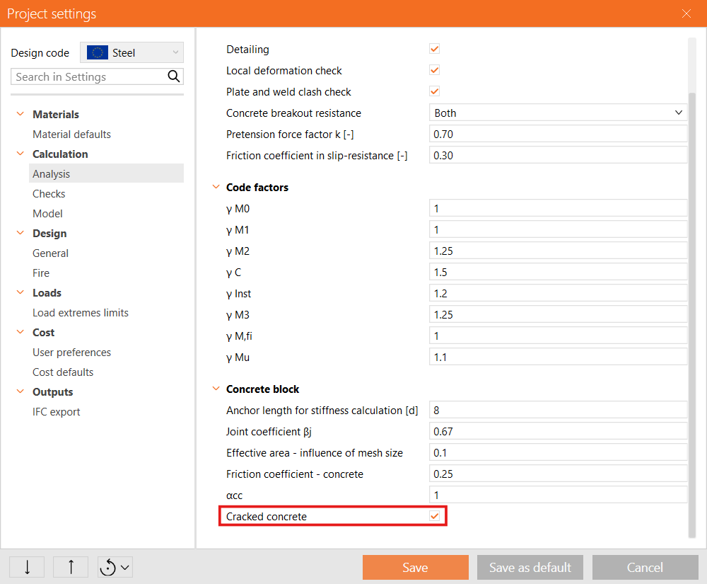
In the Code setup, you can switch the concrete setting to uncracked, which increases the capacity for anchor code checks. For EN standards, this affects the Concrete blowout resistance as parameter k5 and Concrete cone resistance as parameter k1. While for AISC standards, it influences the Concrete breakout strength and parameter Ψc,N. By default, the concrete is set to cracked but can be changed to uncracked in Project settings.
Disable the concrete cone breakout (pull-out) check
Special cases of anchoring steel beams or columns to slender concrete blocks, such as near concrete wall edges, present challenges primarily in the assessment of concrete cone pull-out. In these scenarios, the concrete cone is insufficient, requiring an alternative approach to be employed.
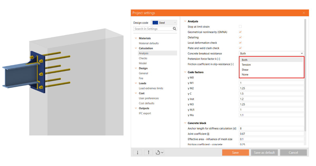
In IDEA StatiCa Connection, you can disable the concrete breakout resistance check in the Code setup and choose from the following options:
- Both - Both tension and shear forces are considered in the code-check.
- Tension - Only tension forces are considered, with shear forces assumed to be carried by reinforcement.
- Shear - Only shear forces are considered, with tension forces assumed to be carried by reinforcement.
- None - All forces are assumed to be carried by reinforcement.
For all options except Both, the report explicitly specifies the forces that must be carried by the concrete block's reinforcement to achieve a satisfactory design.
Concrete check - advanced method
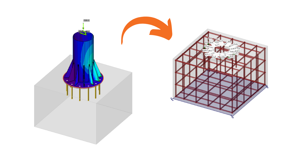
According to the previous setting, the checks for the concrete block may be unsatisfactory without reinforcement. In such cases, you have the option to export the entire anchoring to the Detail application for further analysis and design adjustments. The 3D module enables precise analysis of both the supplementary reinforcement and the concrete block.
More general information about Detail as a solution for anchoring can be found in the article 3D Detail out of Beta.


