
Pullout behavior of cast-in-place anchors with different embedment depths
Introduction
Load capacity of anchors bonded in concrete is dependent on many factors. Concrete and anchor material strength and bond between anchor and concrete are crucial material parameters that determine the anchor behavior. Other factor, not of less importance, is the anchor (and possibly whole foundation block) geometry. Length of anchor and presence of other reinforcement plays also an important role in anchor performance.
The purpose of this article is to verify and validate CFSM based calculation of anchors bonded in reinforced concrete. Various anchor length is chosen according to available literature data [1] for validation. Verification of the presented approach is based on (I) comparison with other well-established software for numerical simulations of material behavior and (II) compliance with standard design codes.
Experiment description
The experimental campaign [1] involves testing full-size anchors bonded in a concrete block. The rods are made of ribbed bar (FeE500B) and are 20 mm in diameter. For the ribbed bar, the steel yield strength is 585 MPa, the ultimate strength is 700 MPa, the ultimate strain at failure is 16%, and the elastic modulus is 210 GPa. Three different depths (100, 150, 200 mm) are being tested to observe bond, concrete cone, or rod failure. The anchors are cast in a reinforced concrete block (2250x1850x600 mm) to prevent splitting failure and edge effects. The EDF(Electricity of France)-recommended minimum reinforcement is installed, consisting of one layer of 20 and 25 mm diameter ribbed bars in both directions on the upper and lower parts of the block.
Additionally, some 12 mm diameter stirrups are installed to support the two layers of reinforcement. The reinforcement rate is 0.64%. The concrete grade used is C40/50. The concrete block is secured using two metal sections connected to the test slab with four prestressing bars. No confining pressure is applied around the anchorage. The hydraulic jack is fixed to the anchorage by two symmetrical rods. The quasi-static tensile loading is displacement-controlled with a loading rate of 1 mm/min, and the load is applied until the anchor fails.
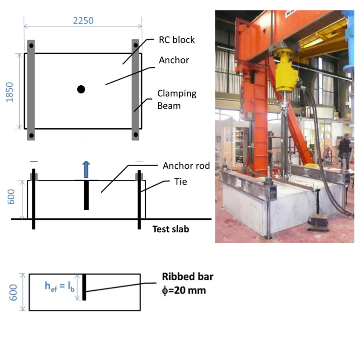
1) Pull out test setup - coming from article: Pullout behavior of cast-in-place headed and bonded anchors with different embedment depths - Fabien Delhomme, Thierry Roure ,Benjamin Arrieta, Ali Limam
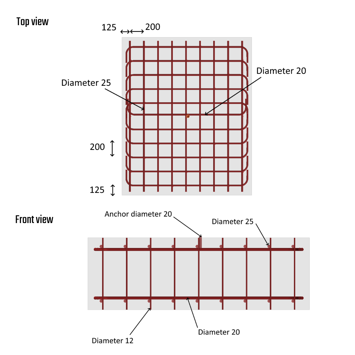
2) Reinforcements and anchor layout
3D CSFM -Compatible Stress Field Method
Theory
3D CSFM defines the concrete behavior based on the Mohr-Coulomb plasticity theory for monotonic loading. The method examines concrete behavior in terms of principal stresses, while neglecting the concrete tensile strength. The effect of concrete tension is only taken into account in Tension stiffening of steel rebars.
The reinforcement bars are linked to concrete volume finite elements through bond elements, allowing for slip between the concrete and reinforcement. It should be noted that 3D CSFM is not suitable for simulating plain concrete due to the absence of tension, which may result in misleading deformation and model divergence.
Generally, the Mohr-Coulomb theory includes two fundamental properties governing the evolution of the plasticity surface in compression and partially in tension: the internal friction angle φ and cohesion parameter c. 3D CSFM assumes a zero angle of internal friction, leading to a conservative design due to the plasticity surface resembling the Tresca model, which is independent of the first stress invariant. More can be found in Theoretical Background [2].
Model assembly
The FEA model is constructed using concrete tetrahedral elements of higher order, with embedded 1D rod representing reinforcements interconnected via MPC( Multi-Point-Constraints) and bond elements to allow slip. The reinforcement bars are split into two surface layers with a cover of 60 mm and shear links (see Fig. 2). The model utilizes surface support with restricted X, Y, Z degrees of freedom over a width of 200 mm. Casted anchors are positioned in the middle of the testing specimen, and the length of the anchor varies from 100-200 mm to test all possible failure modes.
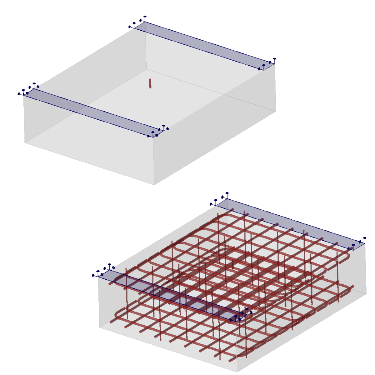
3) Model assembly
Anchor model
The anchor is modeled using a ROD element that can only transfer compression and tension. The important aspect is the bond model and how the anchor is connected to the surrounding concrete to ensure the flow of forces and stress during an interaction between the concrete, anchor, and reinforcements. The connection has a specific linear shear stiffness Gb, which depends on the modulus of elasticity of concrete Ecm and the diameter of the anchor. More about the bond model can be found in Theoretical Background [2].
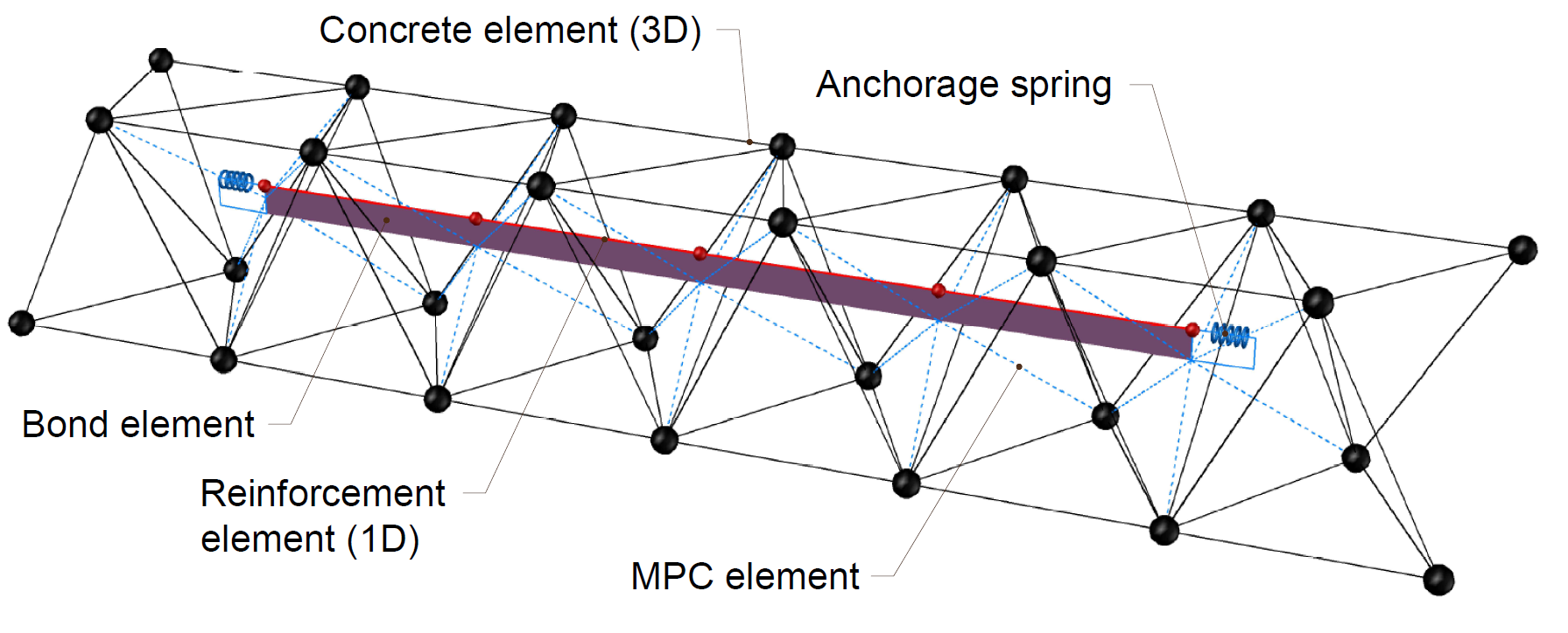
4) Bond model and MPC
Design standards
CEB-FIB mode code 2020
The engineers have the support in the code and valid standards. This statement evokes the impulse to compare the experimental solution with code - solutions to verify the safety of current standards and codes. The concrete properties C40/50 have been taken from code properties. Material properties for reinforcement bars and anchors were experimentally tested and the data were provided. We have verified the solution for unconfined concrete and the subcategory of good/other bond conditions. The CEB-FIB mode code [3] provides a clear definition of how the bond works. The inputs have been used for numerical simulation of anchor in ABAQUS [4].
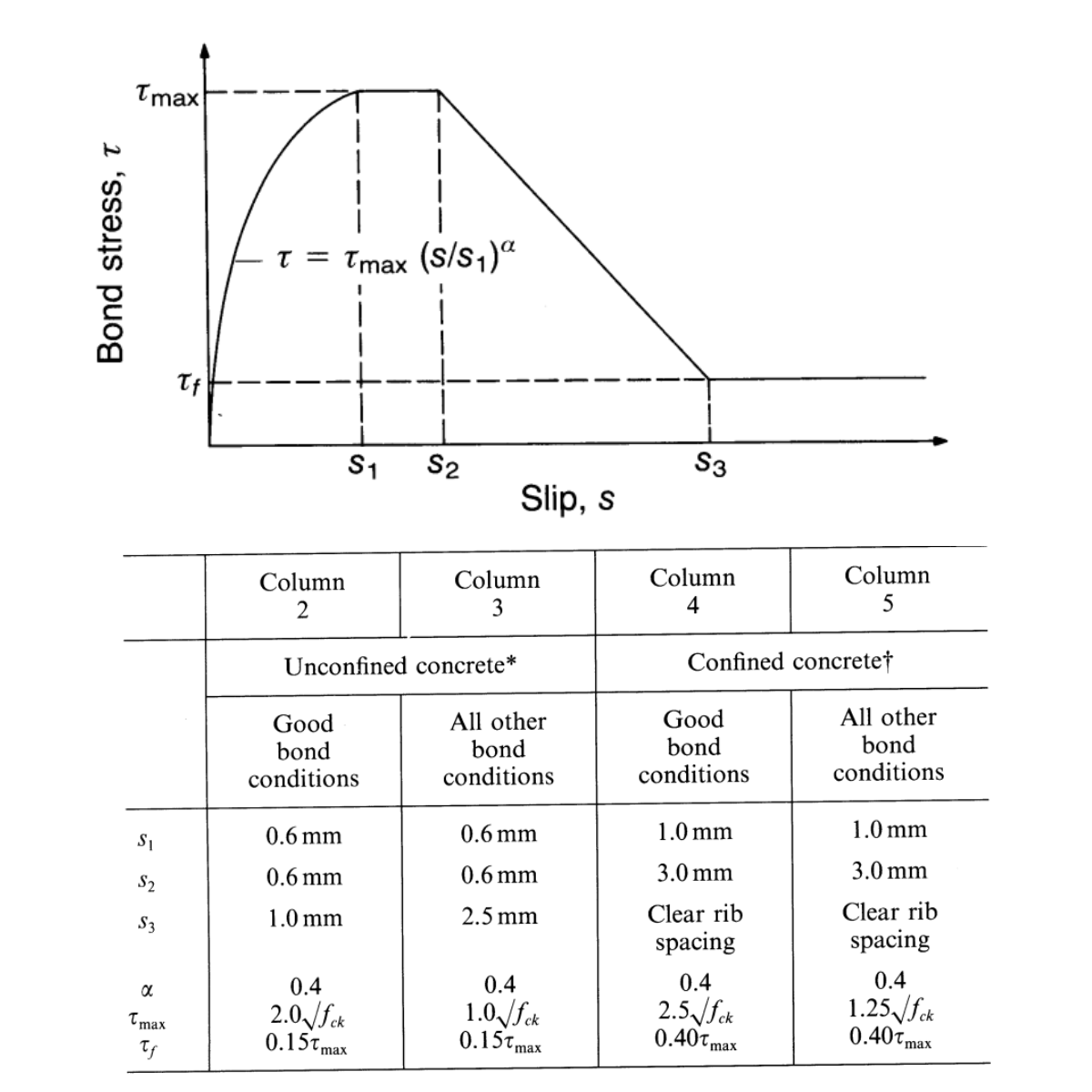
4) CEB-FIB mode code 2020 - Bond model
Eurocode 1992-1-1
The Eurocode 1992-1-1 [5] assumption has been used as a prerequisite for 3D CSFM. The rigidly-plastic model with a characteristic and experimental calculated bond model has been used for simulation and comparison with an experimental solution.
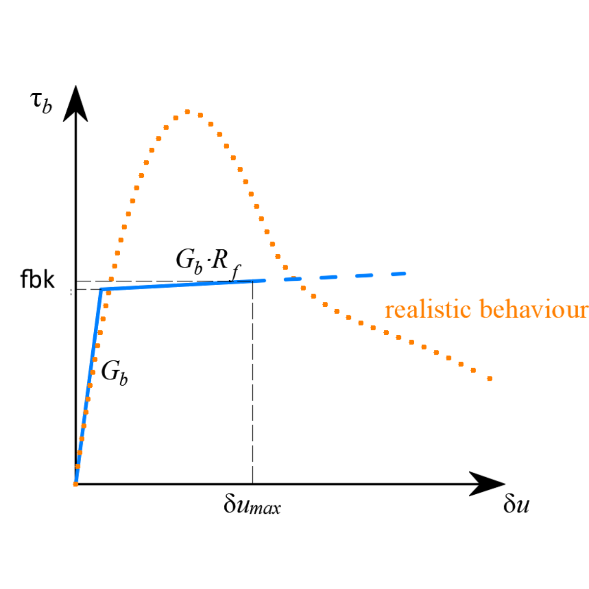
5) Eurocode 1992-1-1 and 3D CSFM - Bond model
Eurocode 1992-4
The characteristic values have also been compared with Eurocode 1992-4 [6], which is implemented in IDEA StatiCa Connection. This provides insight into how the reinforcement in the concrete block affects the local behavior of the anchor. It allows checking for effects such as anchor failure in tension and concrete cone breakout.
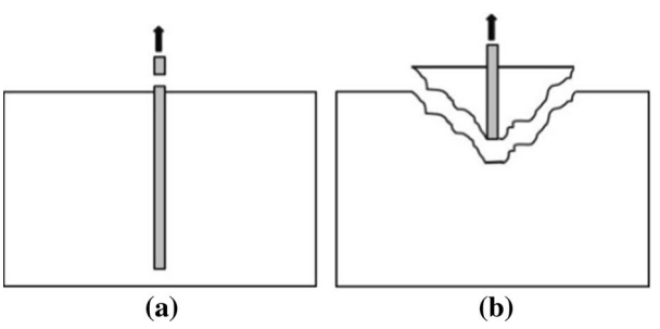
6) a) Rod failure in tension; b) Concrete cone breakout
ABAQUS - Concrete Damage Plasticity
Assumptions
Concrete Damage Plasticity (hereafter CDP) is based on the Drucker-Prager plasticity condition [7]. This model is suitable for materials with internal friction, such as soils or concrete. The tensile strength is significantly lower than the compressive strength and the hydrostatic part of the stress tensor plays a role in the evolution of the plasticity surface. Under general stress, the plasticity condition has the surface of a rotating cone. The material model for compressive and tensile stresses also considers post-critical behavior, which is controlled by the so-called damage parameters, taking values from zero (undamaged) to one (for near-zero stiffness of concrete in compression or tension in the post-critical condition). The larger the damage parameter number, the more the element is violated and does not contribute to the stiffness contribution.
Material models
The uniaxial material model in compression and tension for concrete is based on Thorenfeldt's theory [8]. All inputs are characteristic values that follow the reliability approach of EN 1992-1-1 [5]. The parameters for material model of reinforcement and anchor are taken from chapter " Experimental description," with linear hardening considered in the plastic branch of the diagram.
FEA elements
The C3D8, or hexa-element with a linear basis function and eight integration points, was used for the FEM model of concrete. The concrete and reinforcement comprise T3D2 elements that transmit only axial effects. The interaction between the reinforcement and the concrete is provided by MPC constraints on which tension-stiffening is taken into account, which covers, to some extent, the cohesion model or dowel effect.
Model assembly
The FEA model is designed with symmetry boundary conditions to minimize computation costs and improve the efficiency and speed of the solution. It's important to note that due to the reduced model, the forces on the anchor will reach one-quarter of the maximum force. The mesh has been uniformly distributed using a bias ratio, which consistently decreases the mesh size of the concrete towards the anchor location. The mesh size for concrete is in range ( 5 - 100 mm). Local mesh seeding helps with a gradient of the stresses close to the anchor and more precise results.
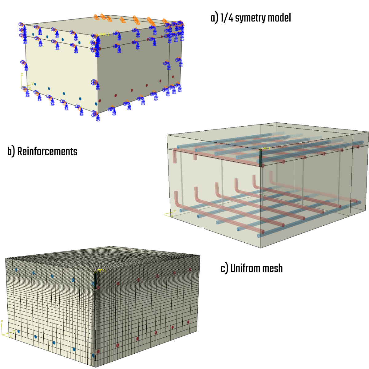
7) Model assembly
Anchor
The anchor is modeled using 3D volume elements. Contact cohesive behavior has been used to model the bond between the concrete and the anchor. The surface interaction enables delamination based on the linear elastic traction-separation law before damage occurs. Hard contact has been used in compression and frictionless behavior in tangential movements. Cohesive behavior in the normal and shear directions has been introduced using volumetric stiffness and damage parameters to represent post-critical behavior. The initiation of post-critical behavior is expressed by maximal bond stress in the normal and shear directions and fracture energy with linear or exponential softening [7].
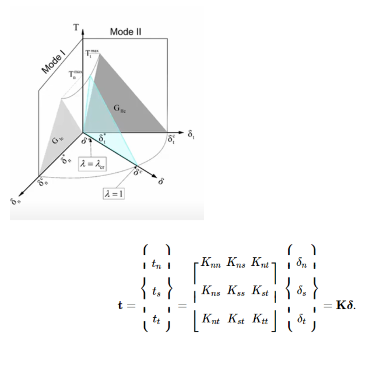
8) Cohesive contact
Results - Anchor 100 mm
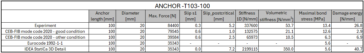
9) Input-output necessary properties for simulation
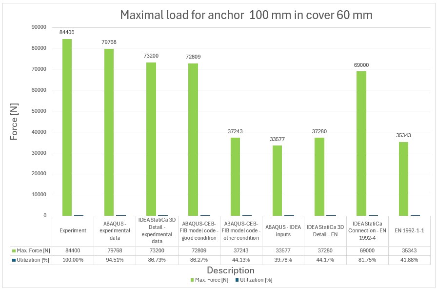
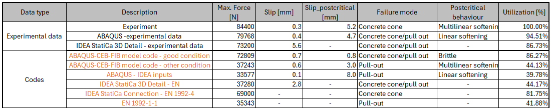
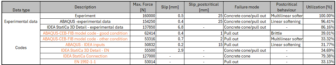
10) Maximal force and utilization versus experiment for anchor 100 mm
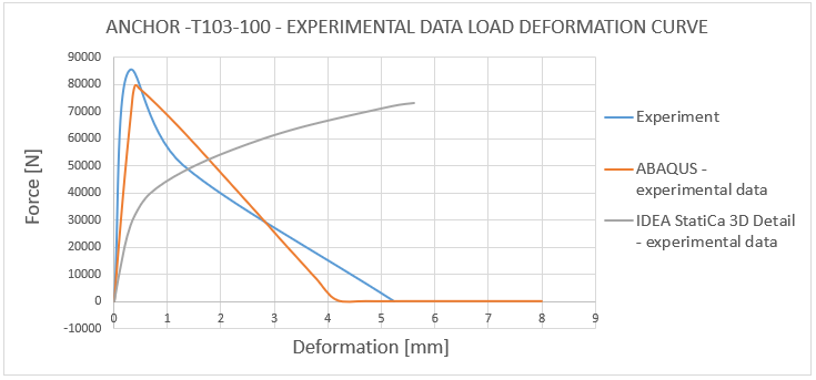
11) Load deformation curve - T103-100 experimental data comparison
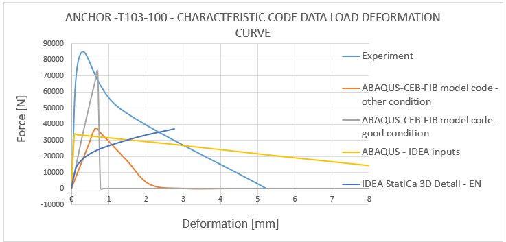
12) Load deformation curve - T103-100 characteristic code data comparison
Results - Anchor 150 mm
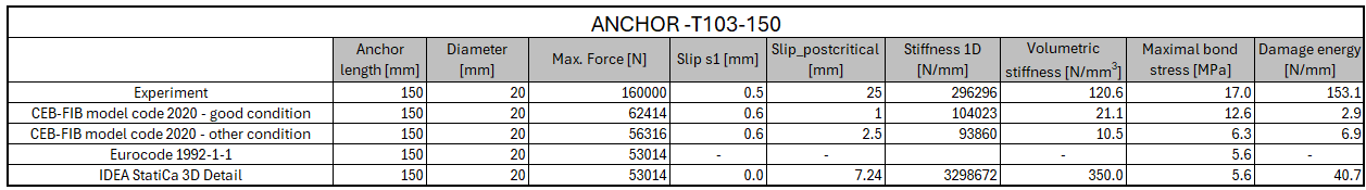
12) Input-output necessary properties for simulation
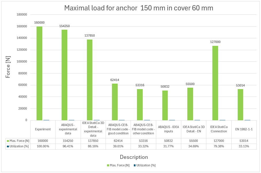
13) Maximal force and utilization versus experiment for anchor 150 mm
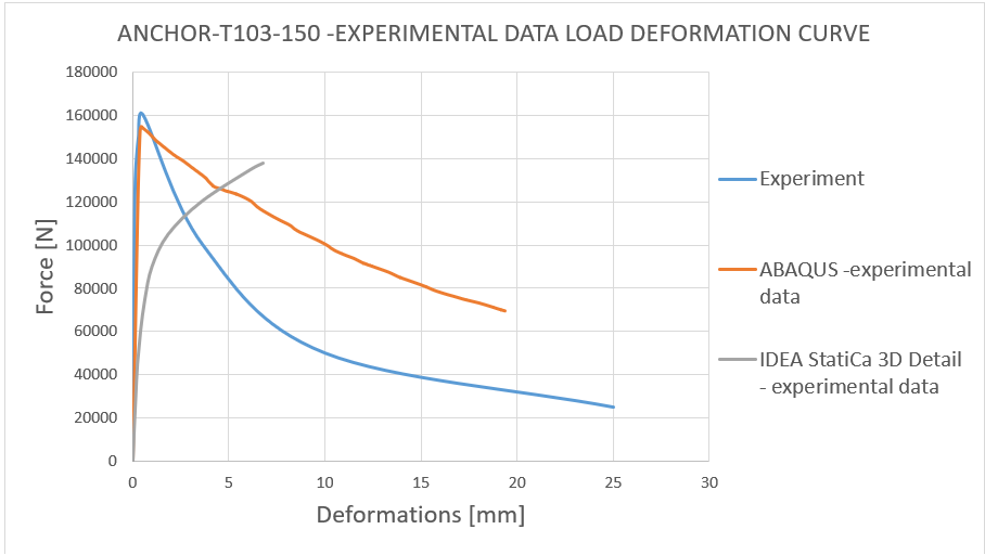
14) Load deformation curve - T103-150 experimental data comparison
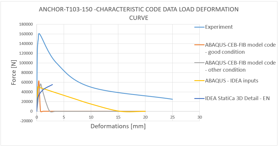
15) Load deformation curve - T103-100 characteristic code data comparison
Results - Anchor 200 mm
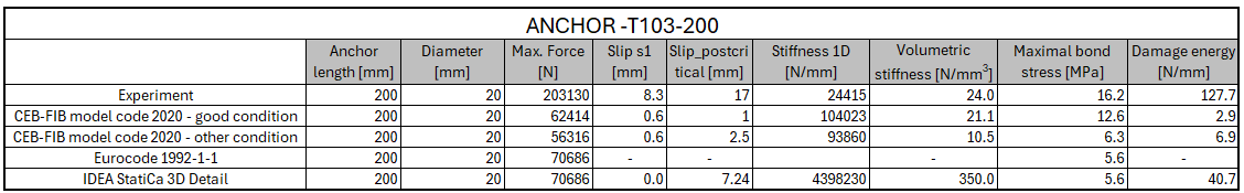
16) Input-output necessary properties for simulation
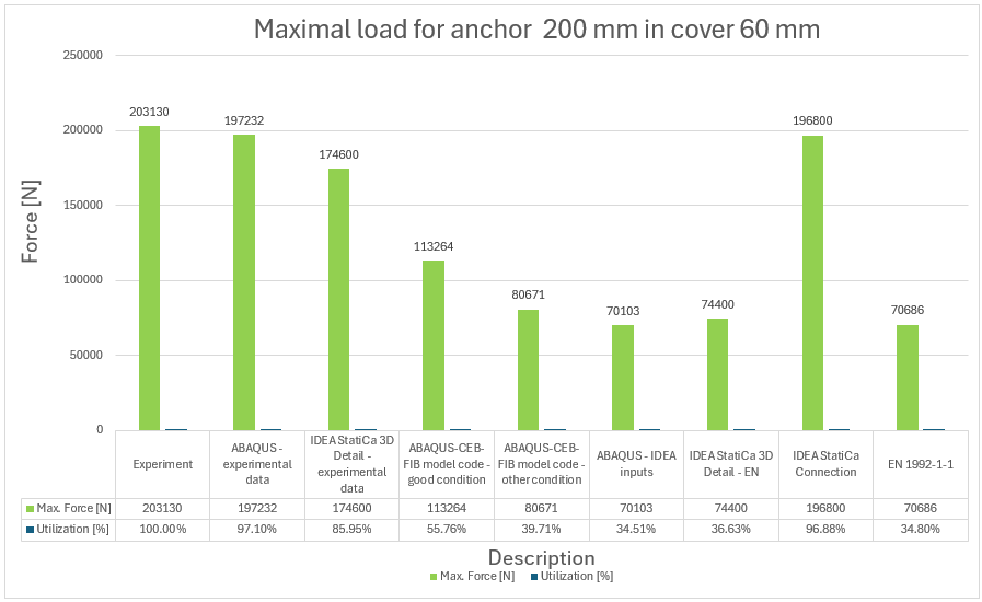
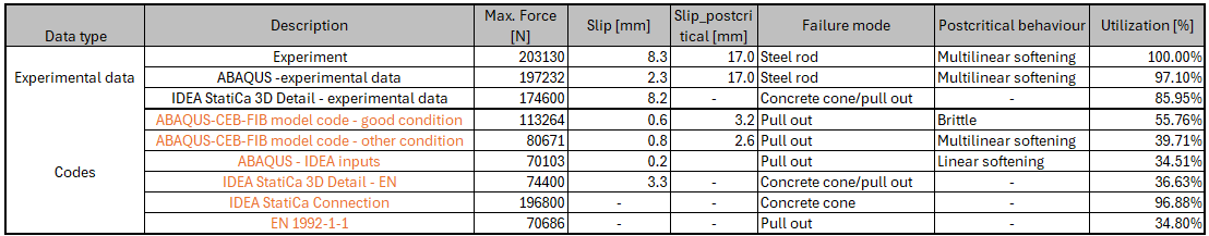
17) Maximal force and utilization versus experiment for anchor 200 mm
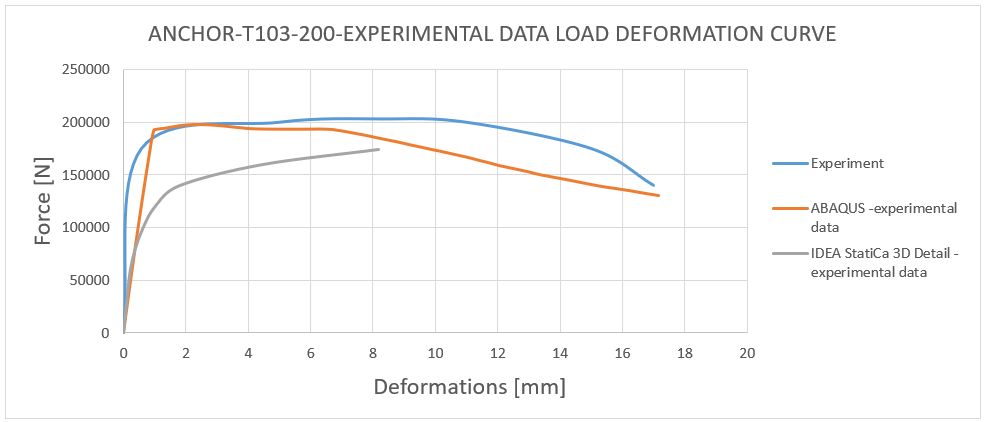
18) Load deformation curve - T103-200 experimental data comparison

19) Load deformation curve - T103-200 characteristic code data comparison
Conclusion
The experimental campaign successfully investigated the behavior of full-size anchors bonded in a reinforced concrete block, using a comprehensive approach that integrated both experimental testing and numerical modeling. By varying the embedment depths of the anchors (100, 150, 200 mm), the study was able to observe different failure modes, including bond failure, concrete cone breakout, and rod failure. The results were rigorously compared with predictions from the CEB-FIB model code and Eurocodes, validating the safety and reliability of current design standards for such anchorage systems.
The use of advanced modeling techniques, such as 3D CSFM and ABAQUS simulations with Concrete Damage Plasticity, provided deeper insights into the interaction between the concrete and reinforcement, as well as the bond behavior under quasi-static tensile loading. The findings confirmed the effectiveness of the proposed methods in predicting anchor performance, emphasizing the importance of accurate material modeling and appropriate boundary conditions in such simulations.
The comparison between the actual behavior observed during the experiment and the numerical solution derived using 3D CSFM and ABAQUS shows an approximate 85% correlation. It can be concluded that no numerical solution exceeds the experimental data and maintains a 15% margin of error compared to the experiment, which is considered acceptable from an engineering perspective. The important aspect is also the failure modes which are fitting, except for the anchor length of 200 mm where in 3D CSFM, a combined mode of concrete cone and pull-out occurred before the steel rod failure. This is because, in this case, the peak loads corresponding to these two failure modes are very close.
The results obtained from CEB-FIB mode code 2020 and Eurocode 1992-1-1 match the experimental results within the range of 30-40%. This indicates that the approach used in the code ensures safety. It's important to note that the values obtained are characteristic values, not design values, so the actual design strength is even lower.
The findings of the report should convey to the engineers that the 3D CSFM method yields safe outcomes in compliance with Eurocode 1992-1-1[5], and results in a conservative design that is integrated within the code itself.
Overall, this study contributes valuable data for improving anchorage design practices, offering evidence that can be used to refine existing codes and ensure that safety margins are adequately maintained in real-world applications. The experimental results, combined with theoretical and numerical analyses, provide a robust framework for understanding the complex interactions in anchored systems, ultimately leading to safe and efficient structural designs.
References
[1]Delhomme, F. & Roure, Thierry & Arrieta, Benjamin & Limam, Ali. (2015). Pullout behavior of cast-in-place headed and bonded anchors with different embedment depths. Materials and Structures. 49. 10.1617/s11527-015-0616-4.
[2] "IDEA StatiCa Detail – Structural Design of Concrete 3D Discontinuities (BETA)." IDEA StatiCa Support Center, 2023. https://www.ideastatica.com/support-center/idea-statica-detail-structural-design-of-concrete-3d-discontinuities-beta
[3]International Federation for Structural Concrete (fib). fib Model Code 2020 for Concrete Structures. Berlin: Ernst & Sohn, 2021.
[4] ABAQUS Standard User's Manual, Version 6.6*. Washington University in St. Louis, 2006. [https://classes.engineering.wustl.edu/2009/spring/mase5513/abaqus/docs/v6.6/books/stm/default.htm]
[5] European Committee for Standardization (CEN). EN 1992-1-1:2004: Eurocode 2 – Design of Concrete Structures – Part 1-1: General Rules and Rules for Buildings. December 2004. https://www.phd.eng.br/wp-content/uploads/2015/12/en.1992.1.1.2004.pdf.
[6] European Committee for Standardization (CEN). EN 1992-4:2018: Eurocode 2 – Design of Concrete Structures – Part 4: Design of Fastenings for Use in Concrete. Brussels: CEN, April 2018
[7]ABAQUS, Inc. ABAQUS User Subroutines Reference Manual, Version 6.6. Washington University in St. Louis, 2006. https://classes.engineering.wustl.edu/2009/spring/mase5513/abaqus/docs/v6.6/books/usb/default.htm?startat=pt05ch18s05abm36.html.
[8] Massone, L. M.; et al. Shear-Flexure Interaction for Structural Walls, 2006. ResearchGate. https://www.researchgate.net/publication/284079633_Shear-flexure_interaction_for_structural_walls (accessed Jan 01, 2006).