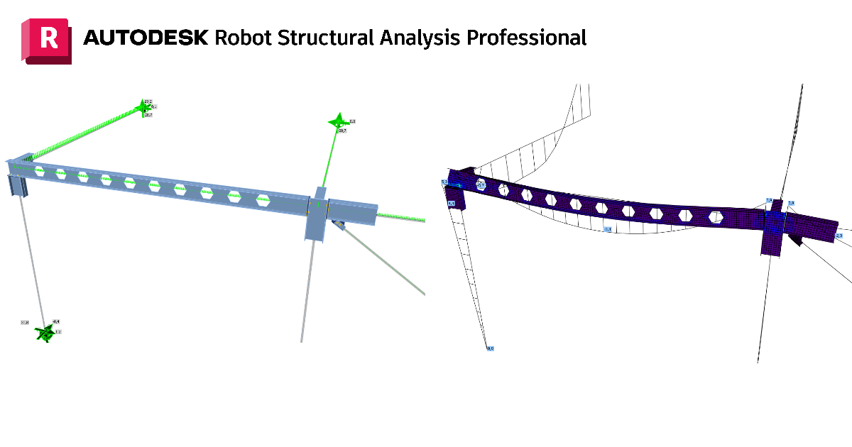
Autodesk Robot Structural Analysis Professional BIM link for steel member design (EN)
How to activate the link
- Download and install the latest version of IDEA StatiCa
- Make sure that you are using a supported version of your FEA/BIM solution
IDEA StatiCa integrates BIM links into your FEA/BIM solutions during its installation. You can check the status and activate more BIM links for software installed after in the BIM link installer.
Please note that some FEA solutions require additional steps to fully activate their BIM link to IDEA StatiCa.
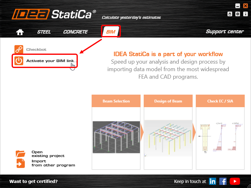
Open IDEA StatiCa and navigate to the BIM tab and open the BIM link installer (Activate your BIM link...).
A notification "Do you want to allow this app to make changes to your device?" may appear, if so, please confirm with the Yes button.
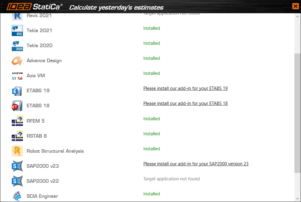
The BIM link for the selected software (if found) is installed. The screen also tells you the status of other BIM links that may have already been installed.
How to use the link
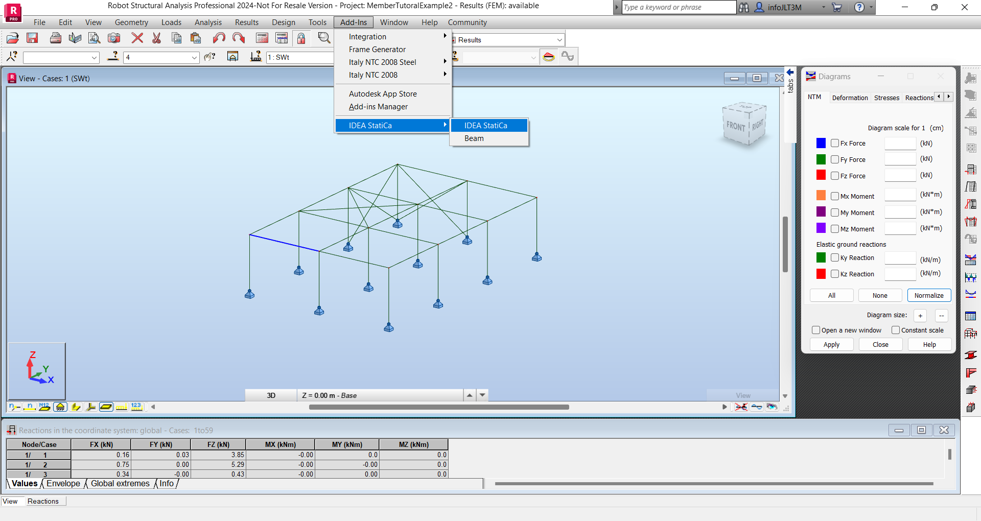
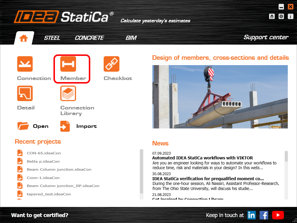
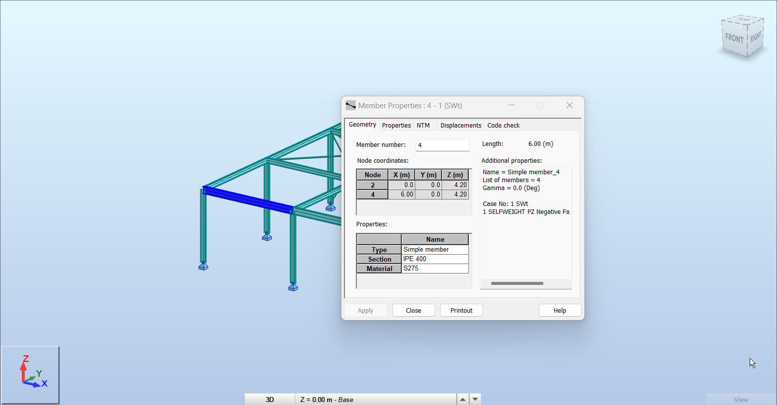
First, open the source file ARSAP-Member-Tutorial.rtd from the provided files for download (at the bottom of this tutorial). There navigate to menu Add-ins then IDEA StatiCa and run IDEA StatiCa. This will start Checkbot.
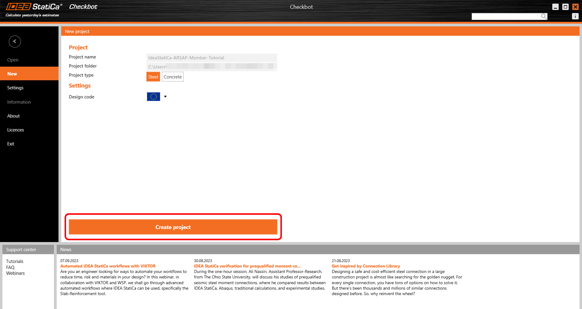
You will be prompted to create a new project.
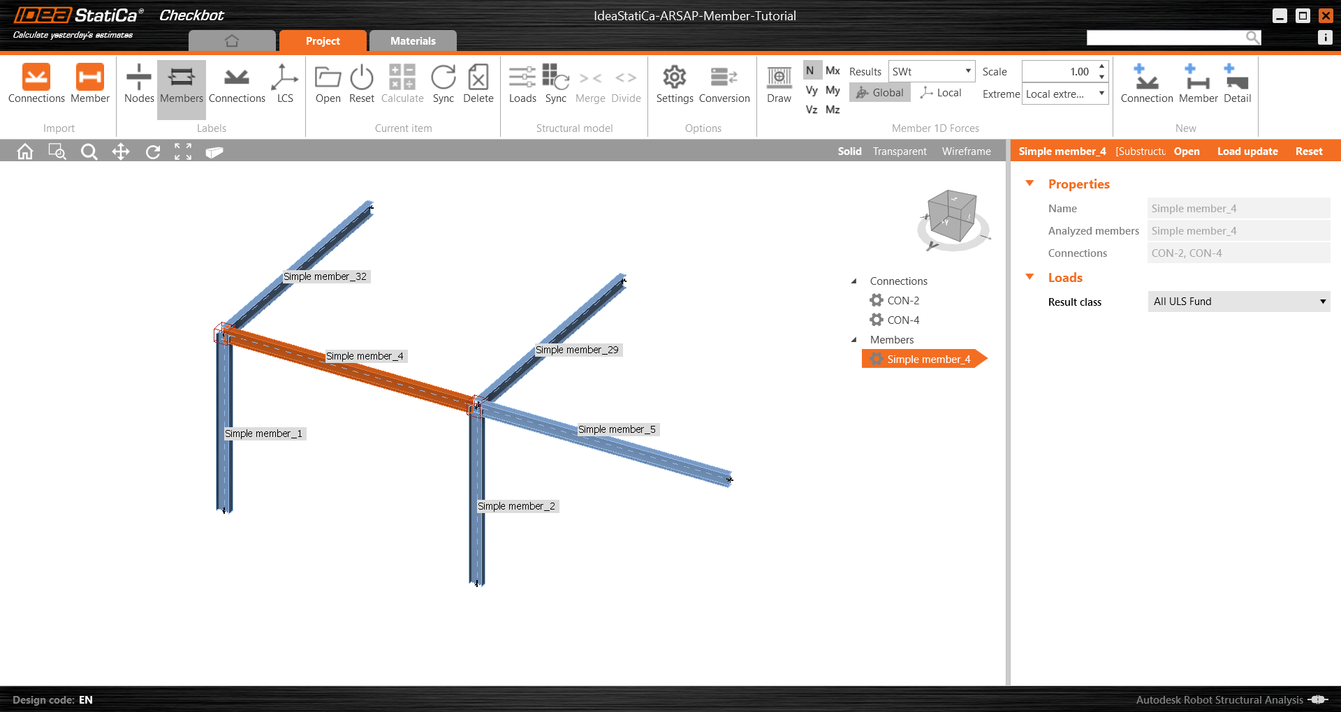
Checkbot opens and you can start the import process. Select the indicated beam in the Robot model and click Member to import it for the analysis in IDEA StatiCa Member under the EN code.
The member is added to the list together with corresponding joints, related members and load combinations without having to manually enter these. Leave the default settings and start configuring the connections first.
Using the BIM Link in this way allows you to not only only you to design the members but also the connections. If you remember, within the Member application connections cannot be designed only modeled. Within Checkbot connections can be modeled and designed using the load combinations from the FEA application. These resultant connections can then be re-used when designing the member. As a result connections are designed more efficiently.
Open Simple member_4 to see the full list of members, connections and load combinations.
Design
There are two ways we can design the member and its connections:
- Online - live within Checkbot maintaining a link to the FEA application
- Offline - again within Checkbot but using the data from the FEA application
For ease (and to help those without Autodesk Robot Structural Analysis Professional) we will now revert to an offline approach. The project folder can also be downloaded and extracted using the link at the bottom of this tutorial.
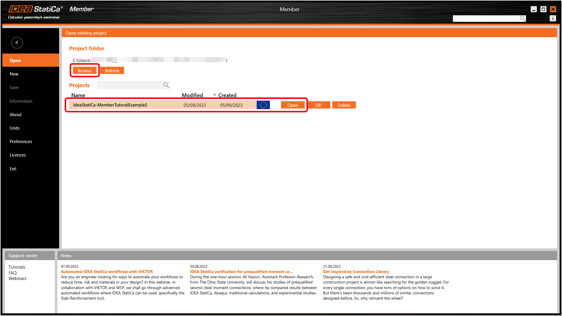
You can exit Checkbot and Robot then open the project in Member by browsing for it.
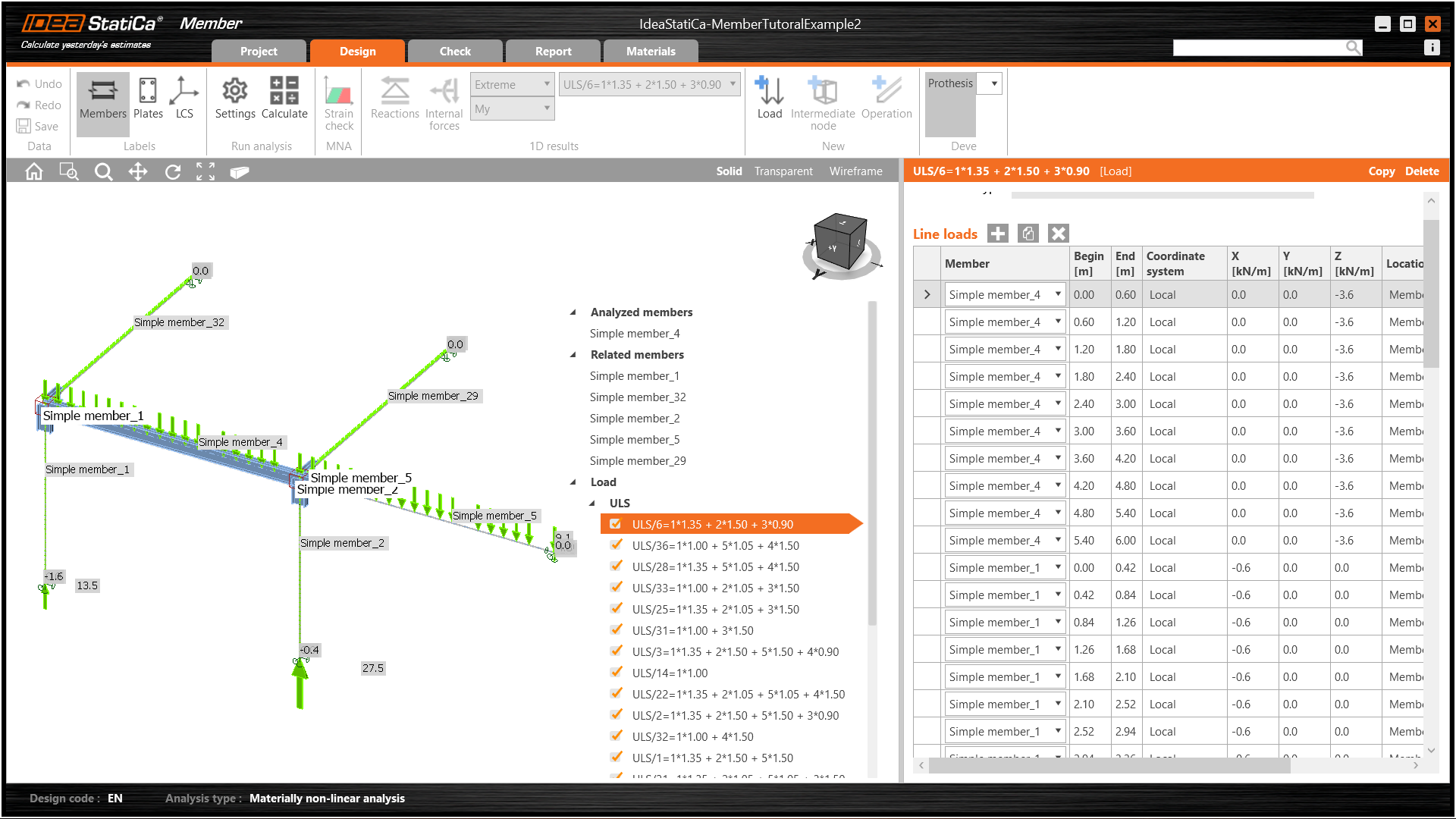
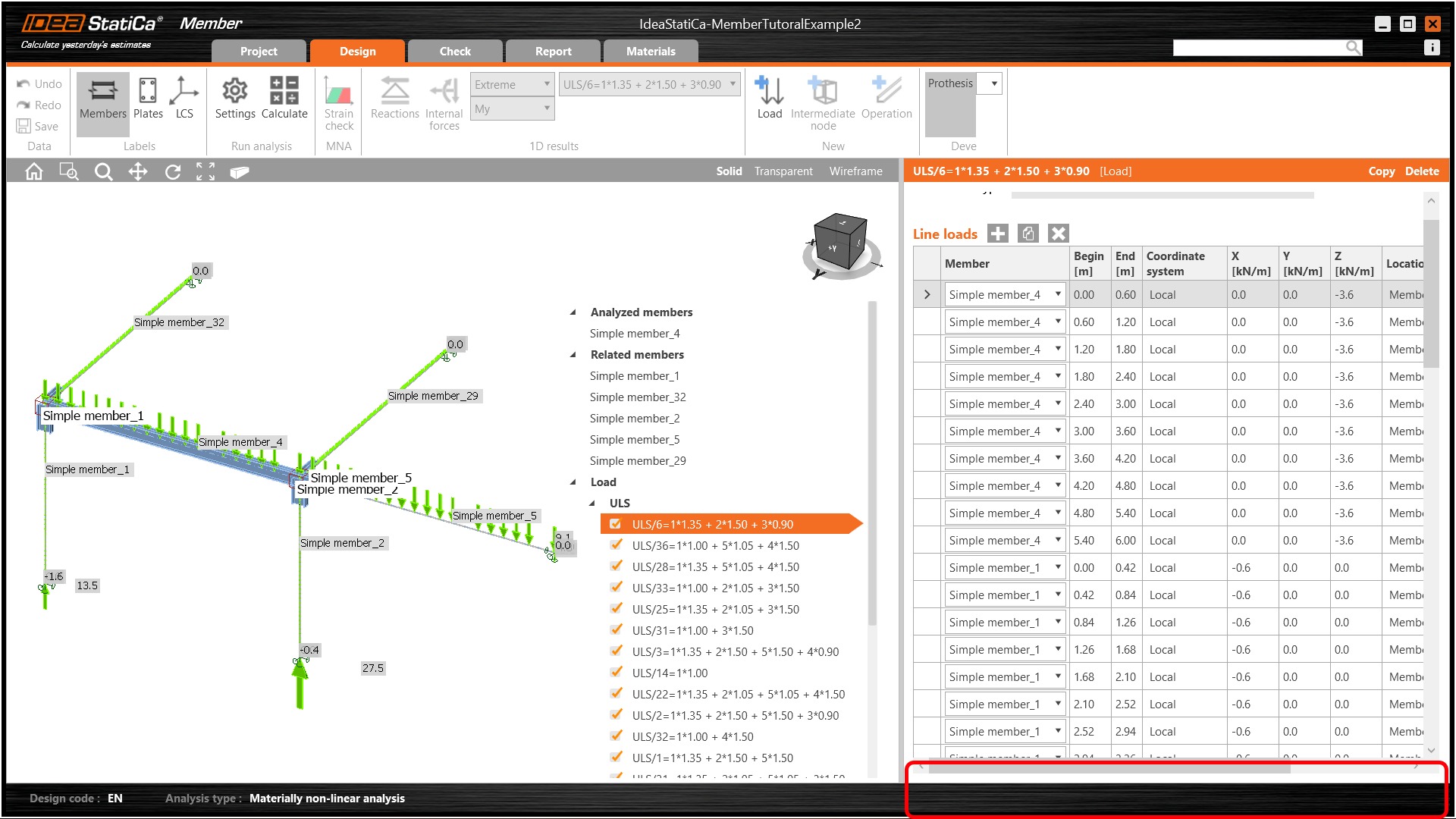
This will open the Member application in so-called offline mode - you can verify this as there will be no application shown in the information bar at the bottom of the screen.
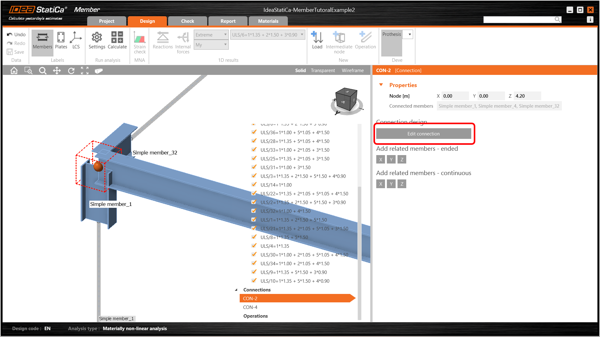
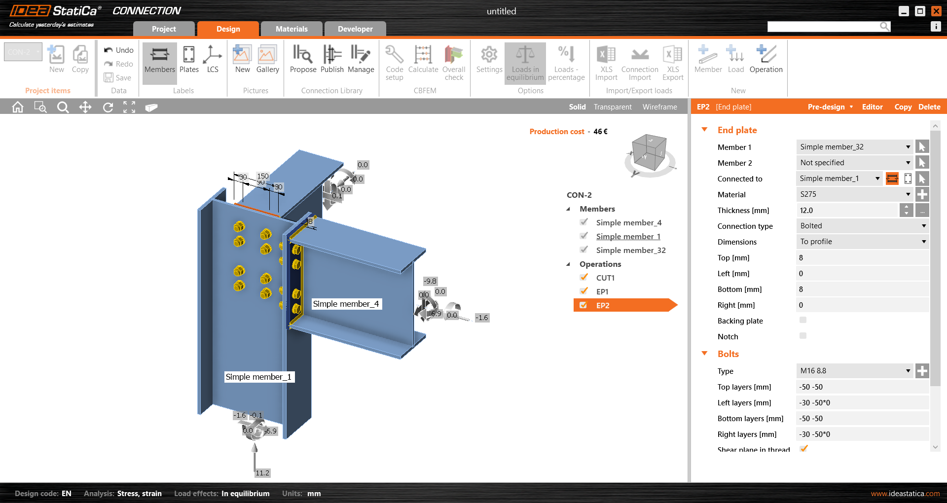
We can now proceed by selecting CON-2 and press Edit Connection.
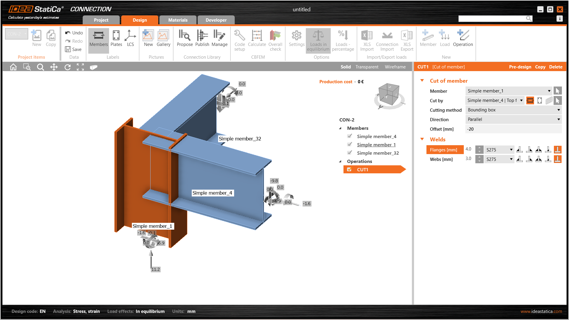
This will open the familiar IDEA StatiCa Connection application. Apply a Cut member operation to the column to increase it's height to 20mm past the top flange of the beam.
Next apply a simple End plate to both of the beams - remembering that you can copy operations.
Save this connection and exit to the Member application.
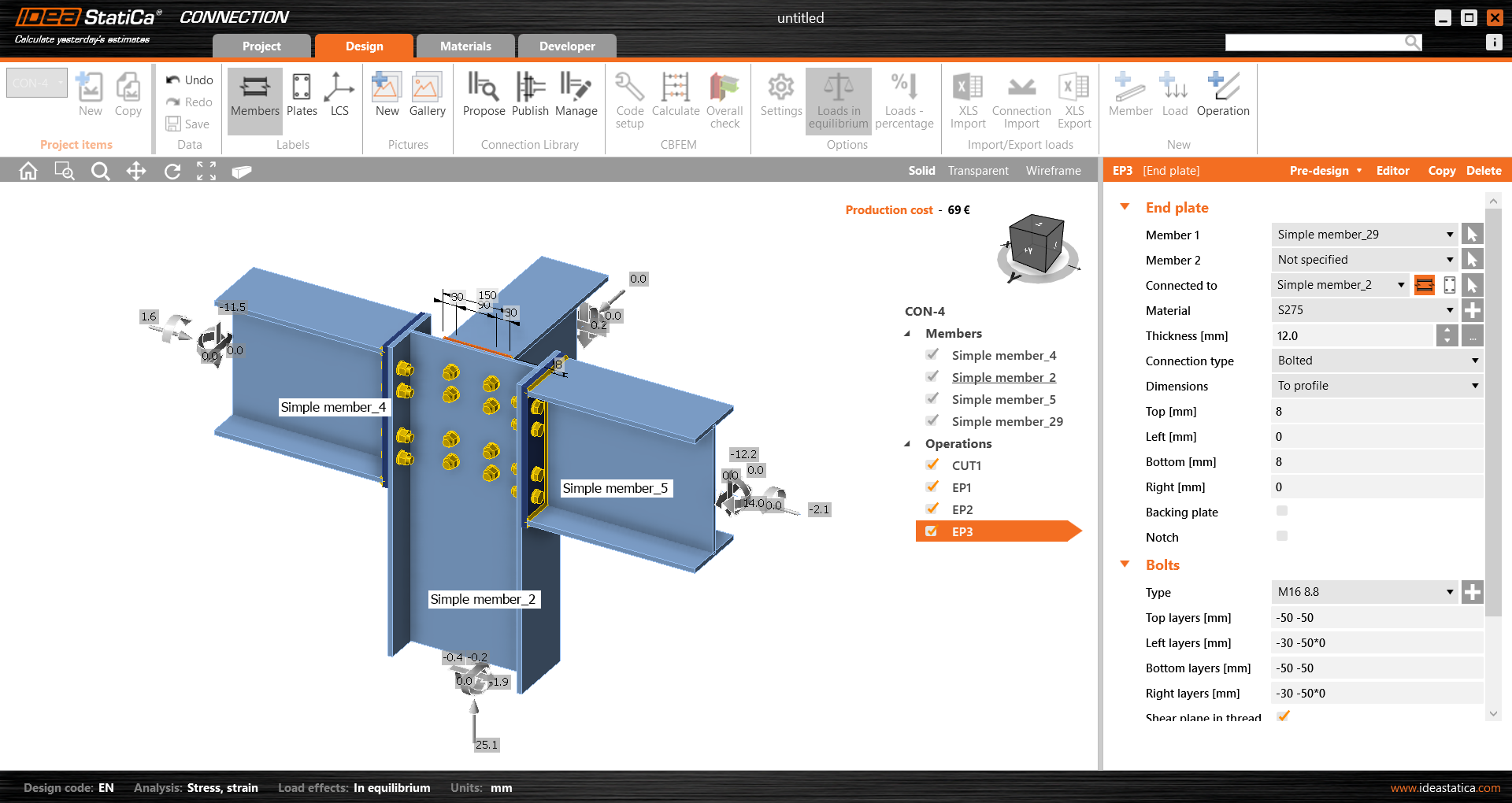
In this example all of the members are the same size so you can very quickly apply the same operations to Con-4.
This is the final appearance of Con-4.
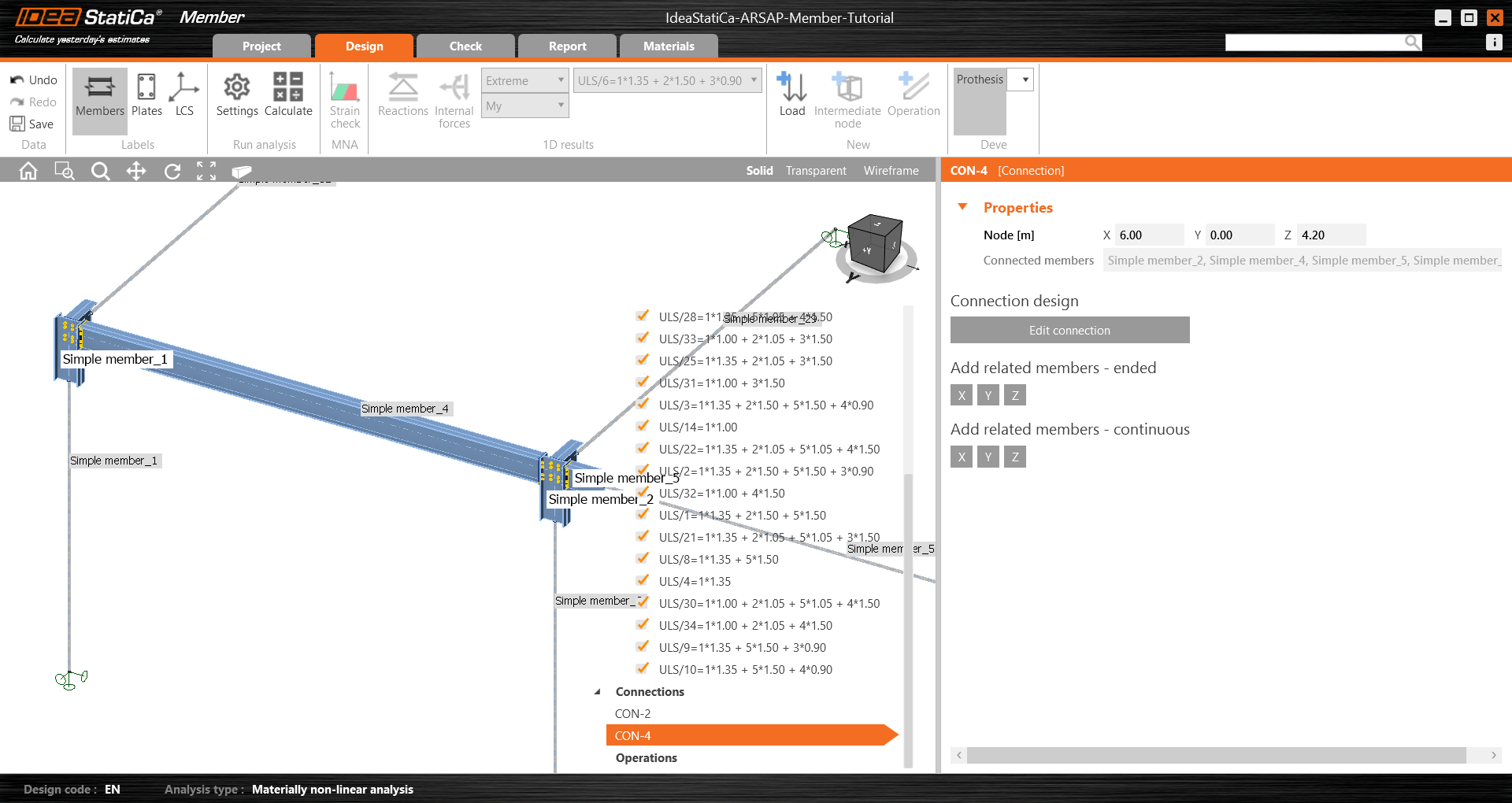
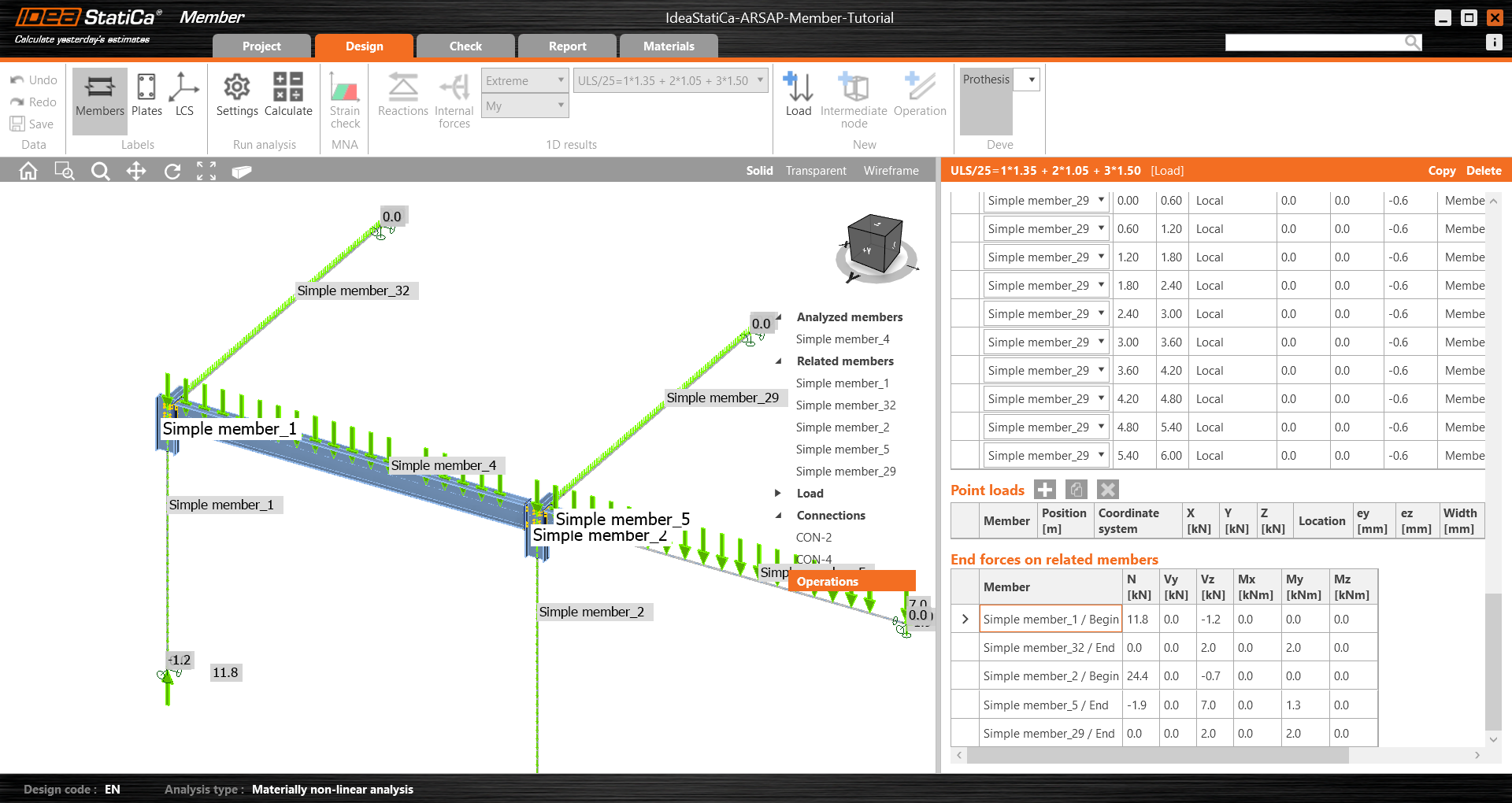
Again Save this connection model and revert back to the Member application. The connections as modeled will be visible.
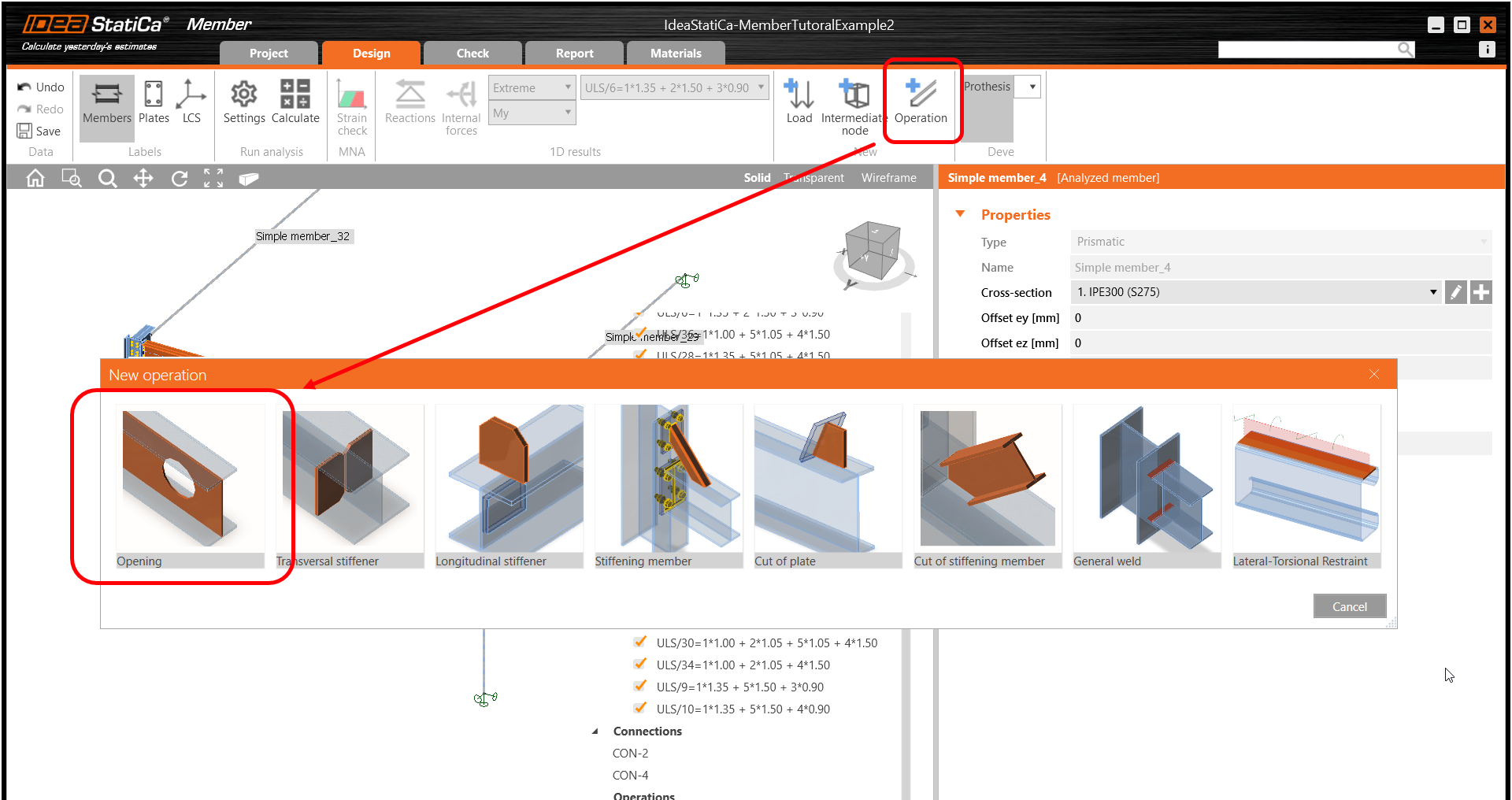
All the data such as geometry and loads have been imported, and all connections have been designed. The model is ready to be analyzed, but first, let's add some openings to the web of the member. Select the member then on Operations in the tree menu and pick the operation Opening.
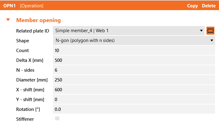
Edit the parameters of the operation, change the size and shape to N-gon (polygon with n sides) and multiply the openings number.
Check
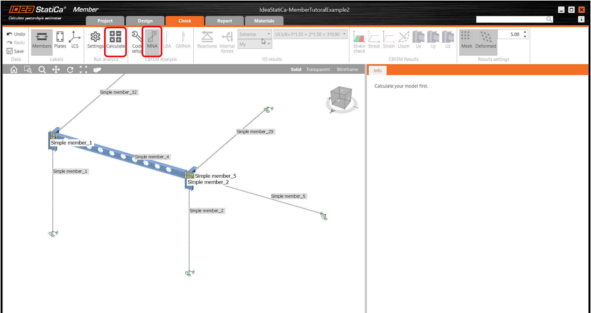
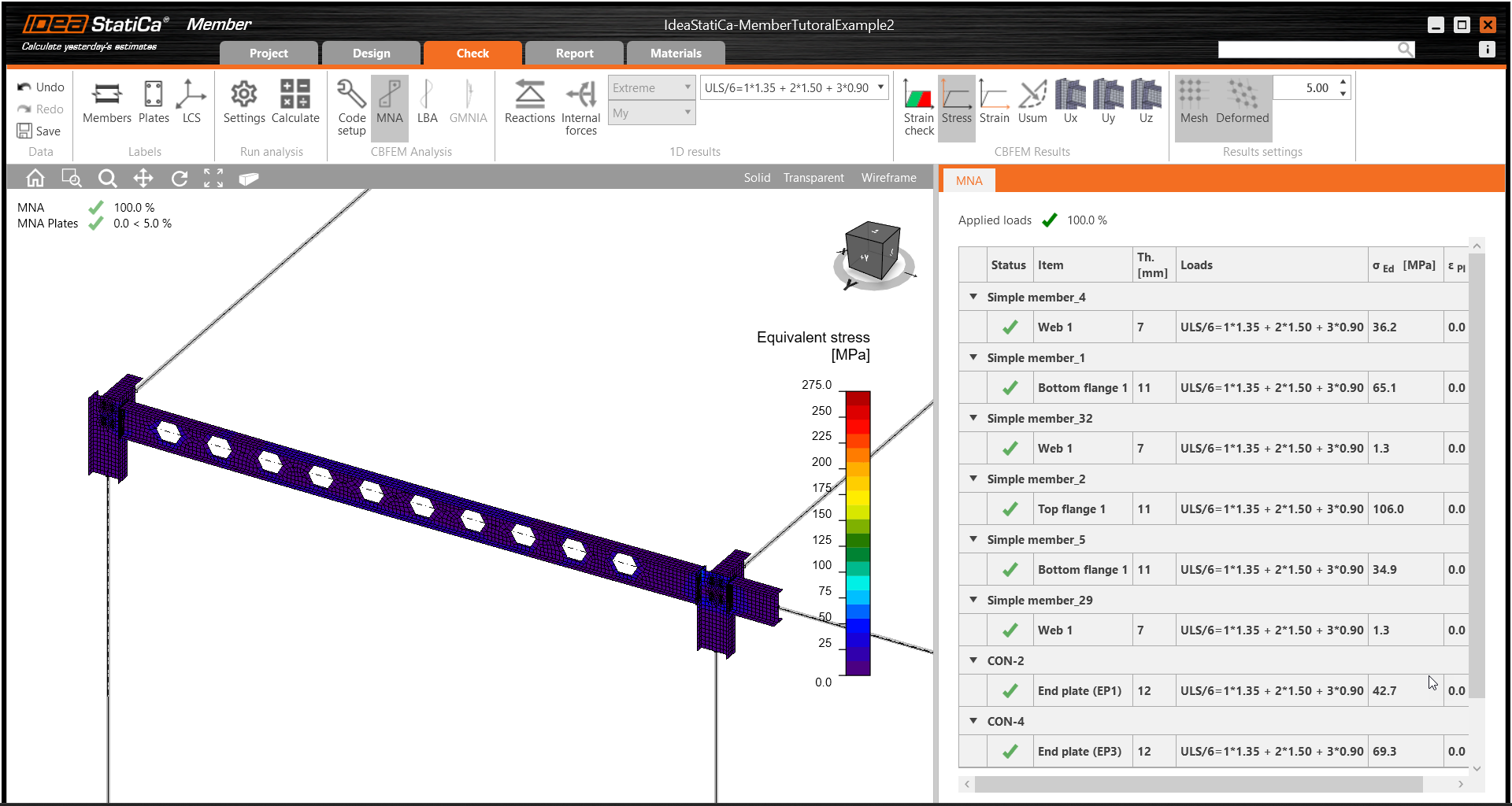
Move to the Check tab, select the MNA (Materially Nonlinear Analysis) and start the analysis by clicking Calculate in the ribbon. The analysis model is automatically generated, the calculation is performed and you can see the overall check displayed together with basic values of check results.
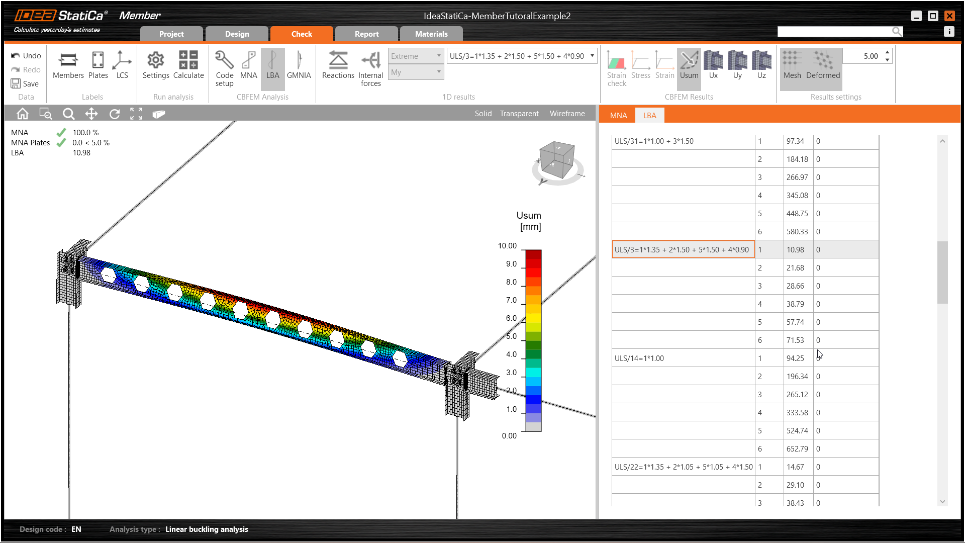
In the next step, switch the analysis type to LBA (Linear buckling analysis) and run the analysis again by clicking Calculate.
When the analysis is finished, you can browse the buckling shape factors in the tab, and by selecting one, e.g. buckling shape 1, you can see it visualized in the 3D window. Selecting the Uy results display highlights the deformation trend.
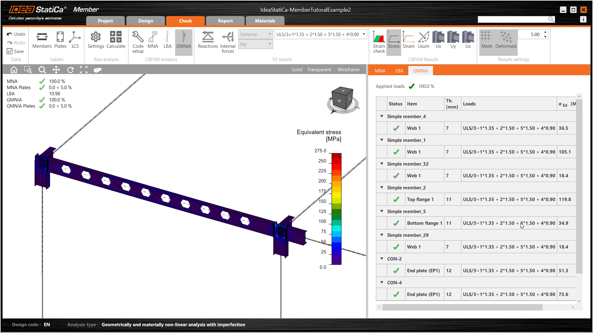
Now you can calculate the GMNIA (geometrically and materially non-linear analysis with imperfections). According to EN 1993-1-1, choose the most critical buckling shape or a combination of buckling shapes and input the initial imperfection of the critical beam. In this case, buckling shape 1 is the most critical one. Switch to the GMNIA tab in the right panel and determine the imperfection of 10 mm (0,5xL/300 = 0,5*6000/300 = 10 mm) to type in as the Amplitude in column 1. Click the Calculate button, for this analysis, the calculation may take several minutes.
The member passed the code-checks with applied initial imperfections and we can browse the results such as stress distribution and internal forces diagram.
Report
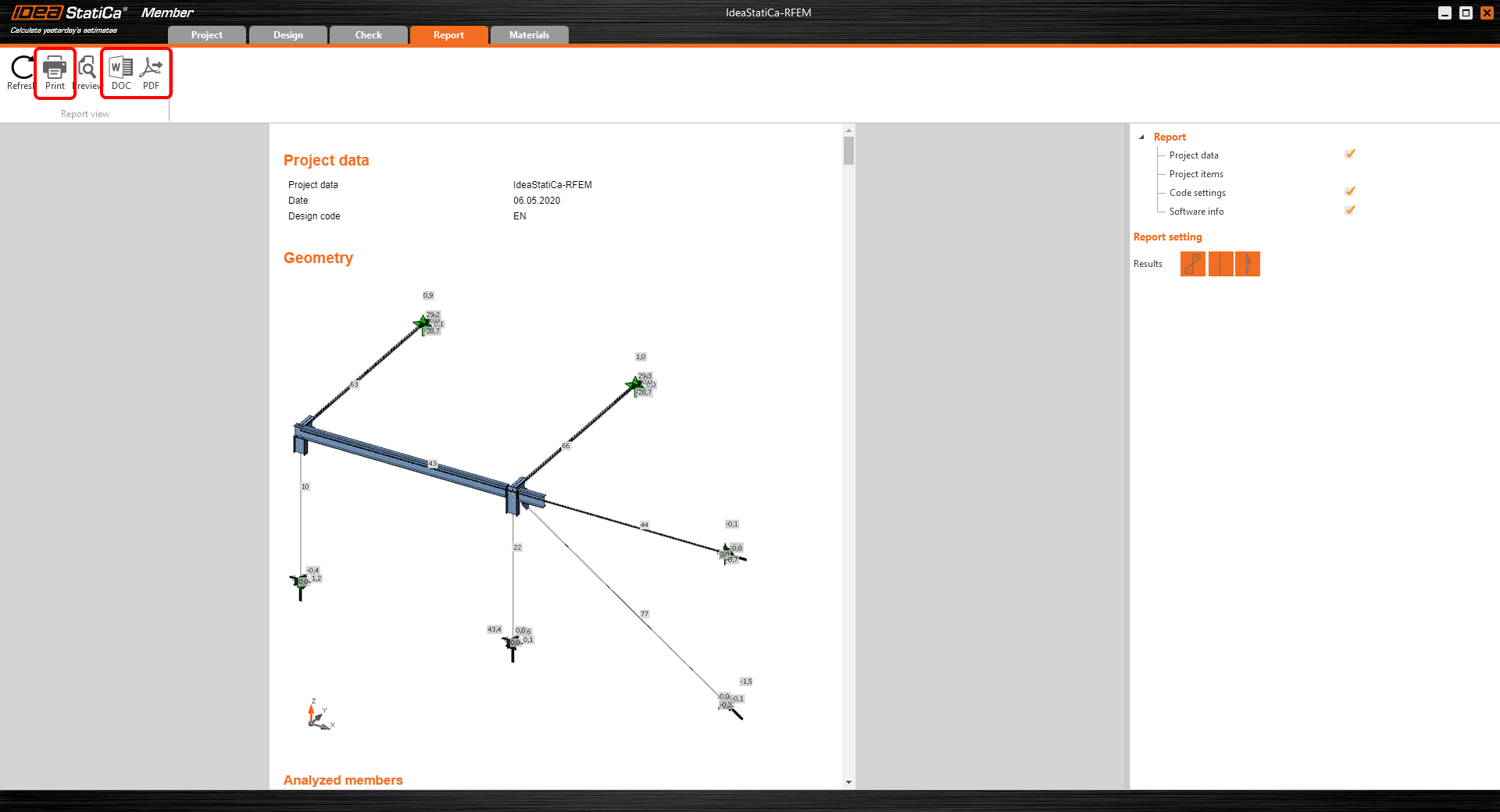
At last, go to the tab Report. IDEA StatiCa offers a fully customizable report to be printed out or saved to .pdf or .doc for an editable format.
You have imported a member from Autodesk Structural Analysis Professional, designed and code-checked it according to Eurocode (EN).
Save the project in IDEA StatiCa Member and close it. The next process is only available when working online, live with the FEA model and Checkbot and offers considerable time savings when things change.
Synchronize models
Rather than re-create models every time the FEA changes Checkbot can Synchronize it's information with that of the FEA application.
To demonstrate the synchronize function, change the cross-section of the analyzed member.
Then, recalculate the project in Autodesk Robot Structural Analysis Professional and open Checkbot again.
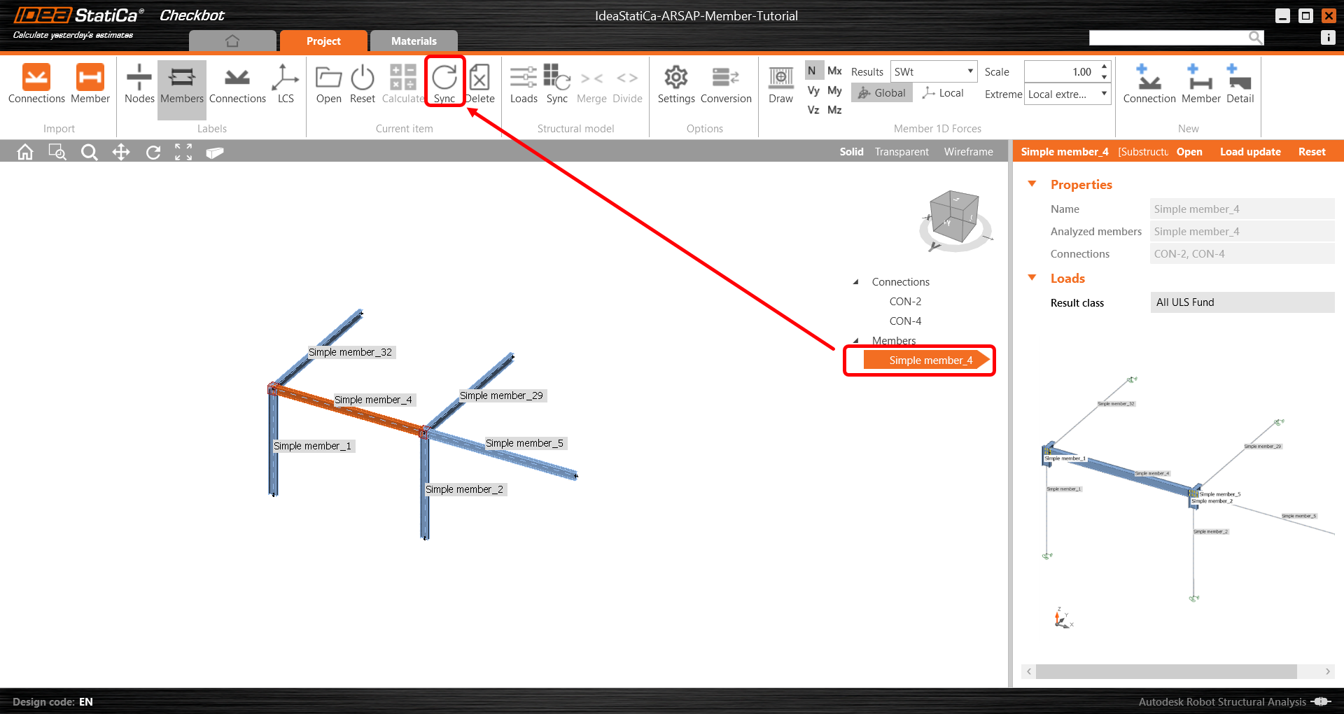
Select the member from the list and click Sync from the Current item panel or Sync from the Structural model panel to update the whole model.
The geometry and load effects were updated and you can click Open to check the project item.
IDEA StatiCa opens and you can see the updated geometry while the design operations keep their settings. However, be mindful that some changes might result in an invalid design and as such these changes should undergo a thorough design review process.
You can check and adjust the design, recalculate and code-check the member, save and close it. Then you can continue importing and code-checking more joints or members.
Want to improve your skills? Visit our Campus
Attached Downloads
- Start - IdeaStatiCa-MemberTutorialExample.zip (ZIP, 306 kB)
- ARSAP-Member-Tutorial.rtd (RTD, 920 kB)


