Serviceability assessments are carried out for stress limitation, crack width, and deflection limits. Stresses are checked in concrete and reinforcement elements according to ACI 318-19 in a similar manner to that specified for the Strength.
Stress limitation
Permissible concrete compressive stresses at service load shall be verified for prestressed members Class U and T. Based on Table R24.5.2.1, there is no stress limitation check required for concrete that is assumed to be cracked. The user needs to set the class of the prestressed member in the design member settings.
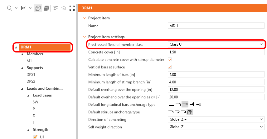
\[ \textsf{\textit{\footnotesize{Fig. 53\qquad Prestressed flexural member class selection}}}\]
The allowable compressive stress for members subjected to transient loads is specified by ACI 318-19 24.5.4.1 as 0.6fc'. The compressive stress limit of 0.45fc' was established to decrease the probability of failure of prestressed concrete members due to repeated loads. This limit also seemed reasonable to preclude excessive creep deformation. At higher values of stress, creep strains tend to increase more rapidly as applied stress increases.
The concrete stress in compression is evaluated as the ratio between the maximum principal compressive stress fc = σc2 obtained from FE analysis for serviceability and the limit value, which is set based on Table 24.5.4.1.
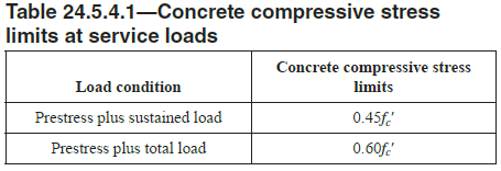
\[ \textsf{\textit{\footnotesize{Fig. 54\qquad Concrete compressive stress limits at service loads}}}\]
In the application, Prestress plus sustained load is treated as a Long-term combination, and Prestress plus total load as a Short-term combination.
Deflection
Based on the selected combination type (long-term or short-term), either long-term or short-term deflection is evaluated. The maximum allowable deflection value shall be determined by the user and shall be considered in accordance with ACI 138-19 24.2.
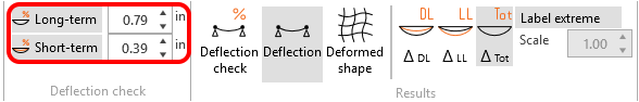
\[ \textsf{\textit{\footnotesize{Fig. 55\qquad Maximum allowable deflection value}}}\]
In the application, it is possible to display the deflections from dead load ΔDL and live load ΔLL separately as well as the total deflection ΔTot (deal+live), all while displaying the deformed shape.
Deflections at trimmed ends cannot be checked.
Crack width
Crack widths and crack orientations are calculated for serviceability short-term or long-term combinations. Since ACI does not directly prescribe limiting crack widths, the user must specify a limiting crack width wlim.
The verifications are presented as follows:
\[\frac{w}{w_{lim}}\]
where:
w short- or long-term crack width calculated by FE analysis,
wlim limit value of the crack width defined by the user.
The method of calculating crack widths used in the application, also described in more detail in this document, is in accordance with ACI 224R-01. It is, therefore, possible to use ACI 224R-01 Table 4.1 to determine the limiting value of crack widths.
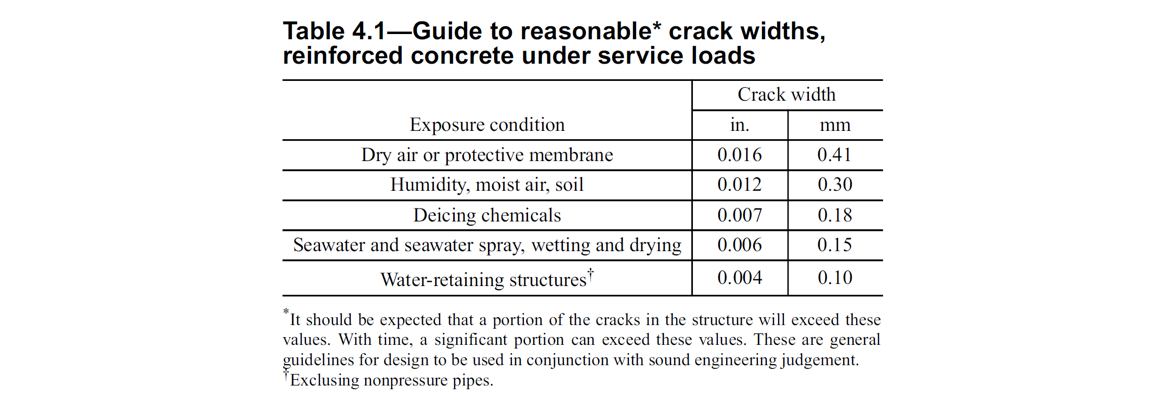
\[ \textsf{\textit{\footnotesize{Fig. 56\qquad Reasonable crack widths for reinforced concrete under service load}}}\]
There are two ways of computing crack widths (stabilized and non-stabilized cracking). In the general case (stabilized cracking), the crack width is calculated by integrating the strains on 1D elements of reinforcing bars. The crack direction is then calculated from the three closest (from the center of the given 1D finite element of reinforcement) integration points of 2D concrete elements. While this approach to calculating the crack directions does not correspond to the real position of the cracks, it still provides representative values that lead to crack width results that can be compared to code-required crack width values at the position of the reinforcing bar.