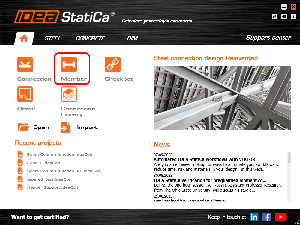
New project
Start by launching IDEA StatiCa and select the application Member (download the newest version).
Create a new project - fill in the name, set the span 24',
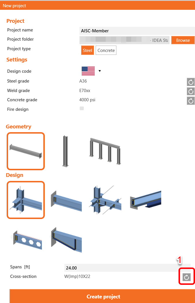
Select a rolled I section,
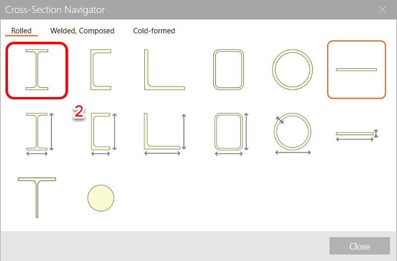
Open the full library,
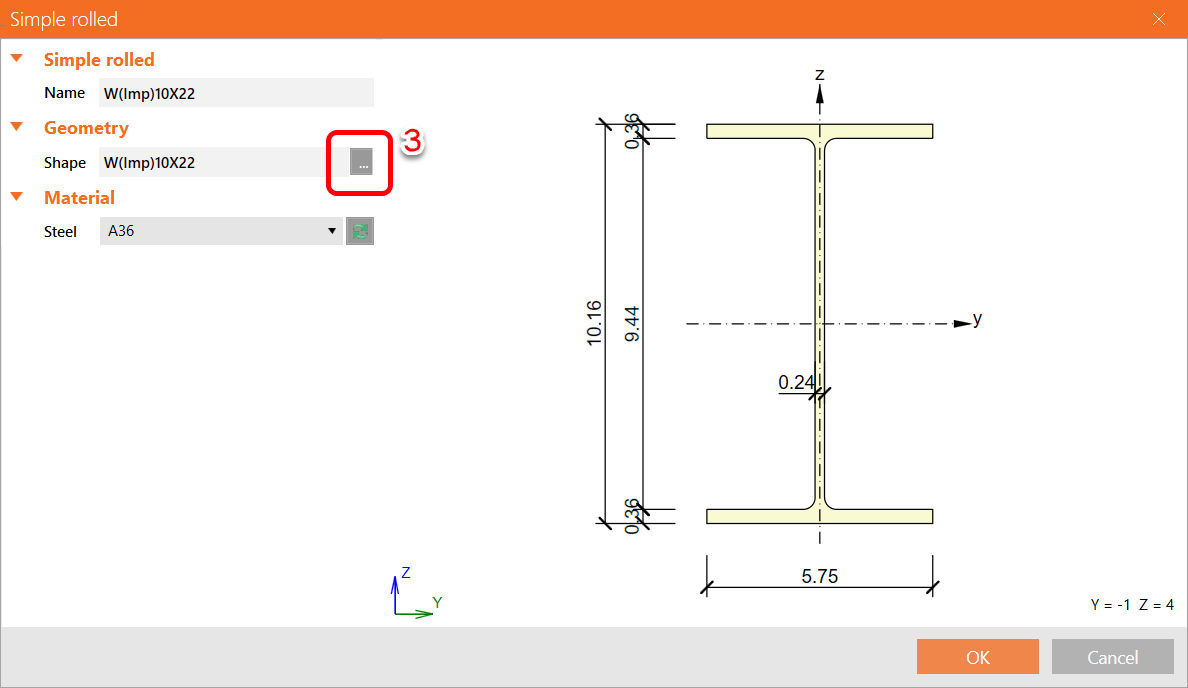
Select the cross-section W10x60 for the beam from the AISC 15.0 library,
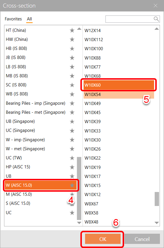
Press OK multiple time and finally click Create Project.
Analyzed member
In this example, you have only one analyzed member AM1, which was created at the same time as the project.
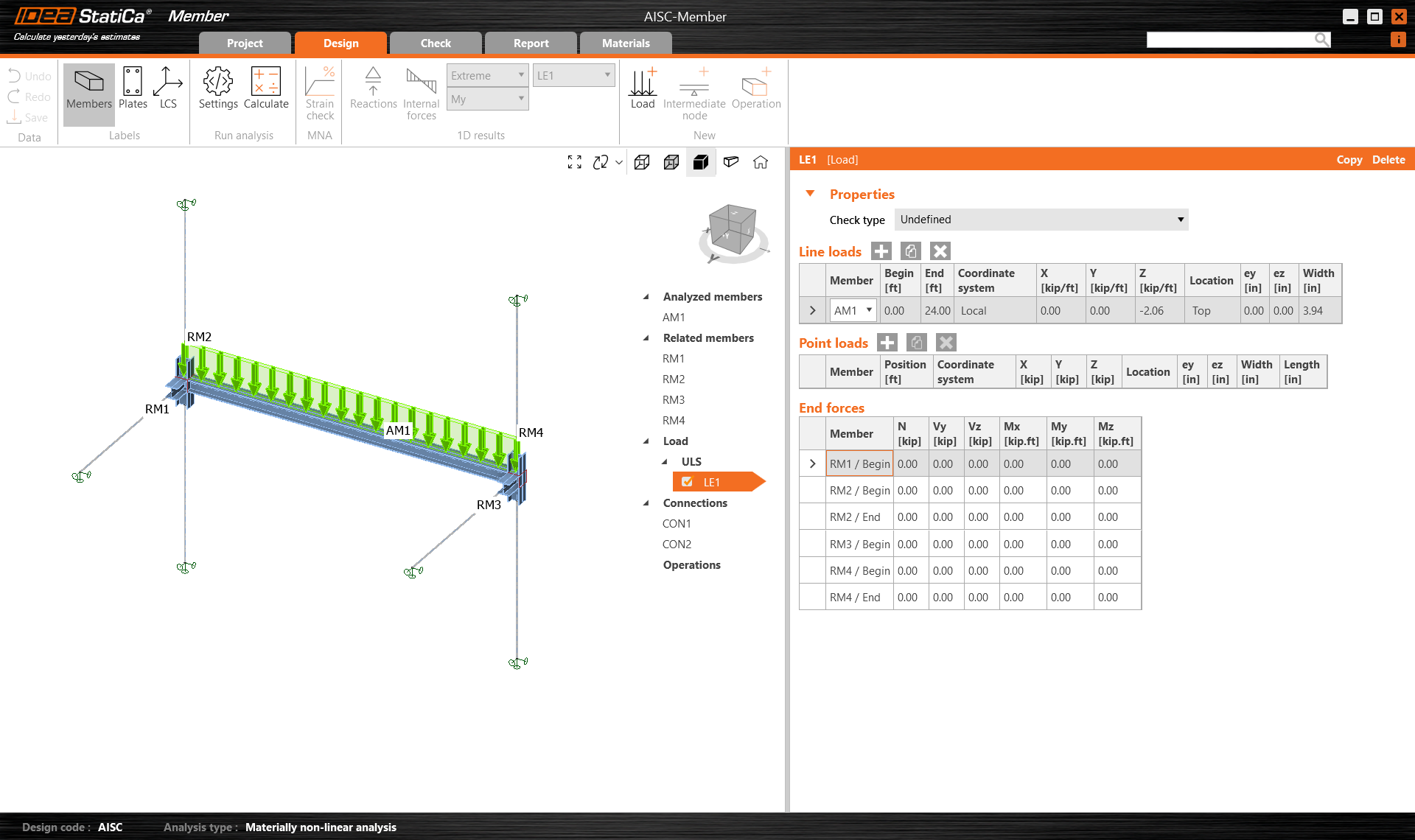
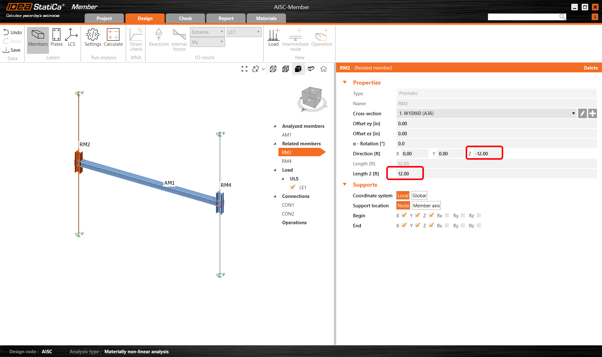
Related members
Four related members were created automatically by the project. However, we only need to keep the two columns the remaining two framing beams can be deleted to finalize the arrangement.
Highlight RM1 and RM3 and press Delete to remove them.
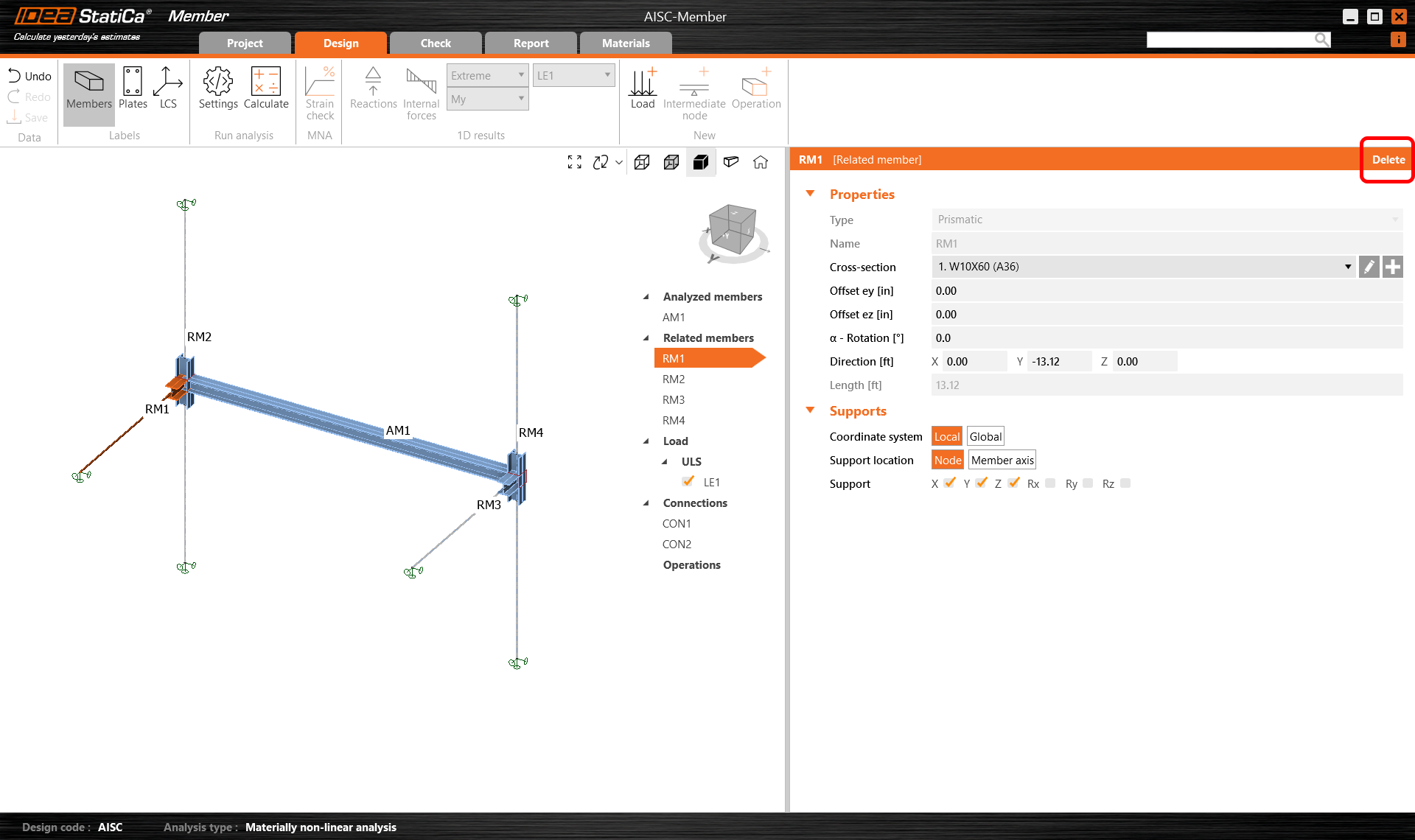
Hightlight RM2 and RM4 and change their coordinates and lengths as shown.
Loads
First, specify the dead load on the beam, where it is placed and the distribution area of the load.
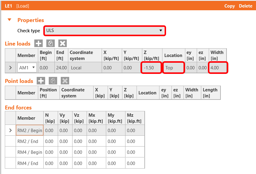
Set the Check type to ULS and enter -1.50kip/ft in the z direction acting on the top flange over a width of 4".
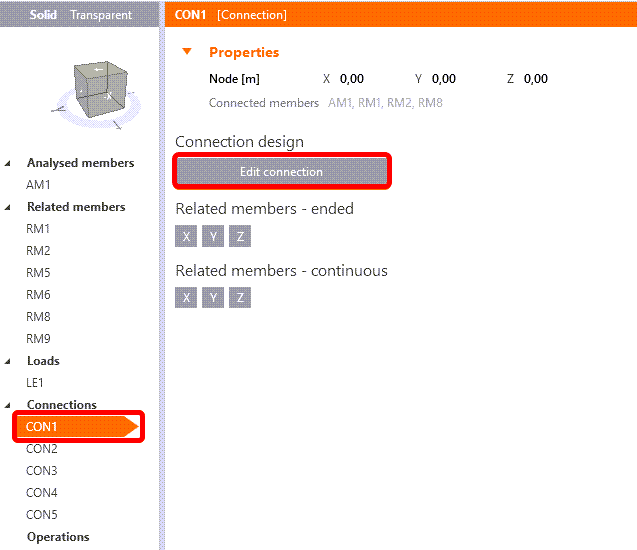
Connections
Click on Connection CON1 and then on Edit connection.
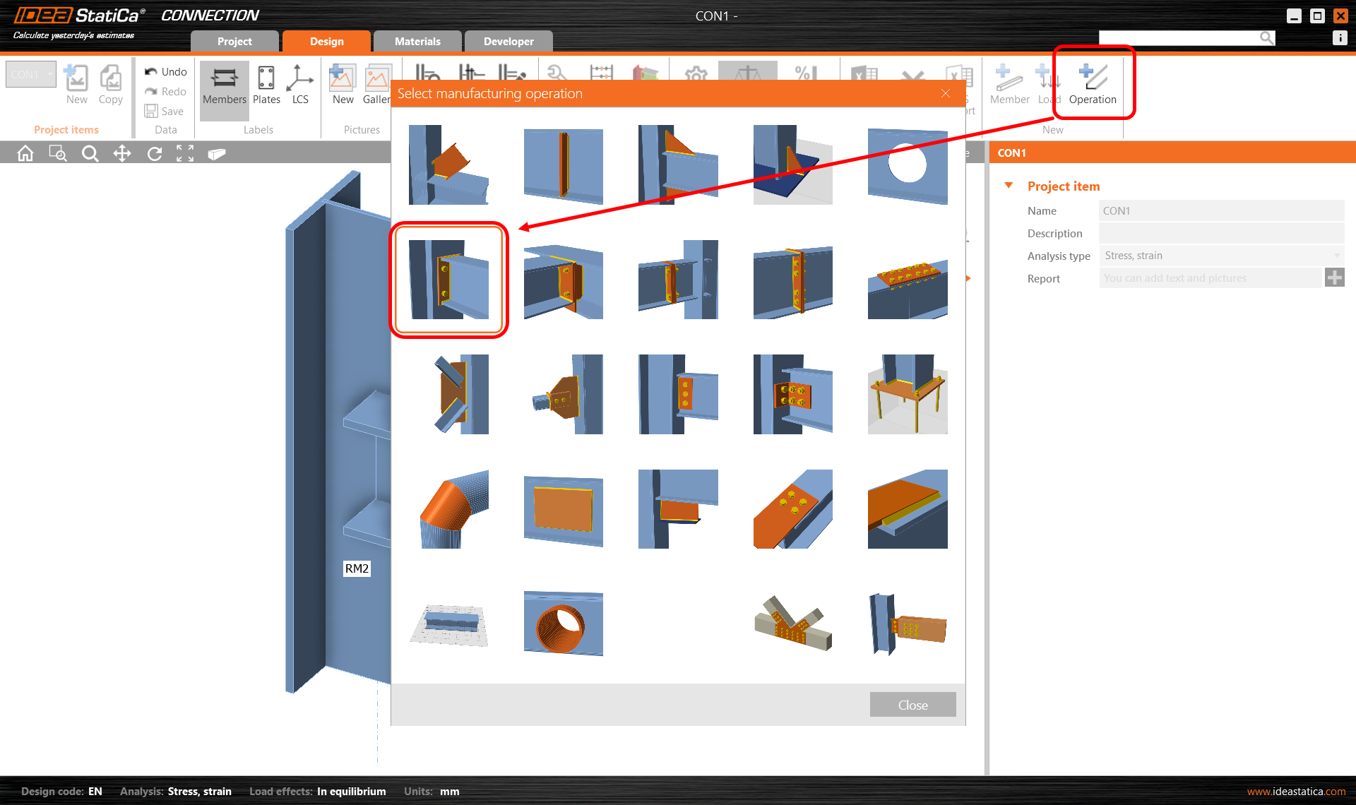
There two ways we can model this simple connection:
- Using an endplate operation
- Using an example from the connection library
As our example is very straightforward we will use option 1.
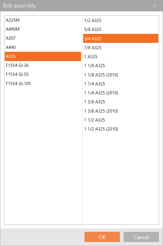
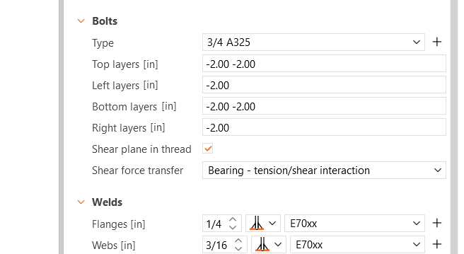
Change the dimensions of the bolt to 3/4 A325, and click OK.
Amend the bolt spacing as shown below:
Save and Exit this connection.
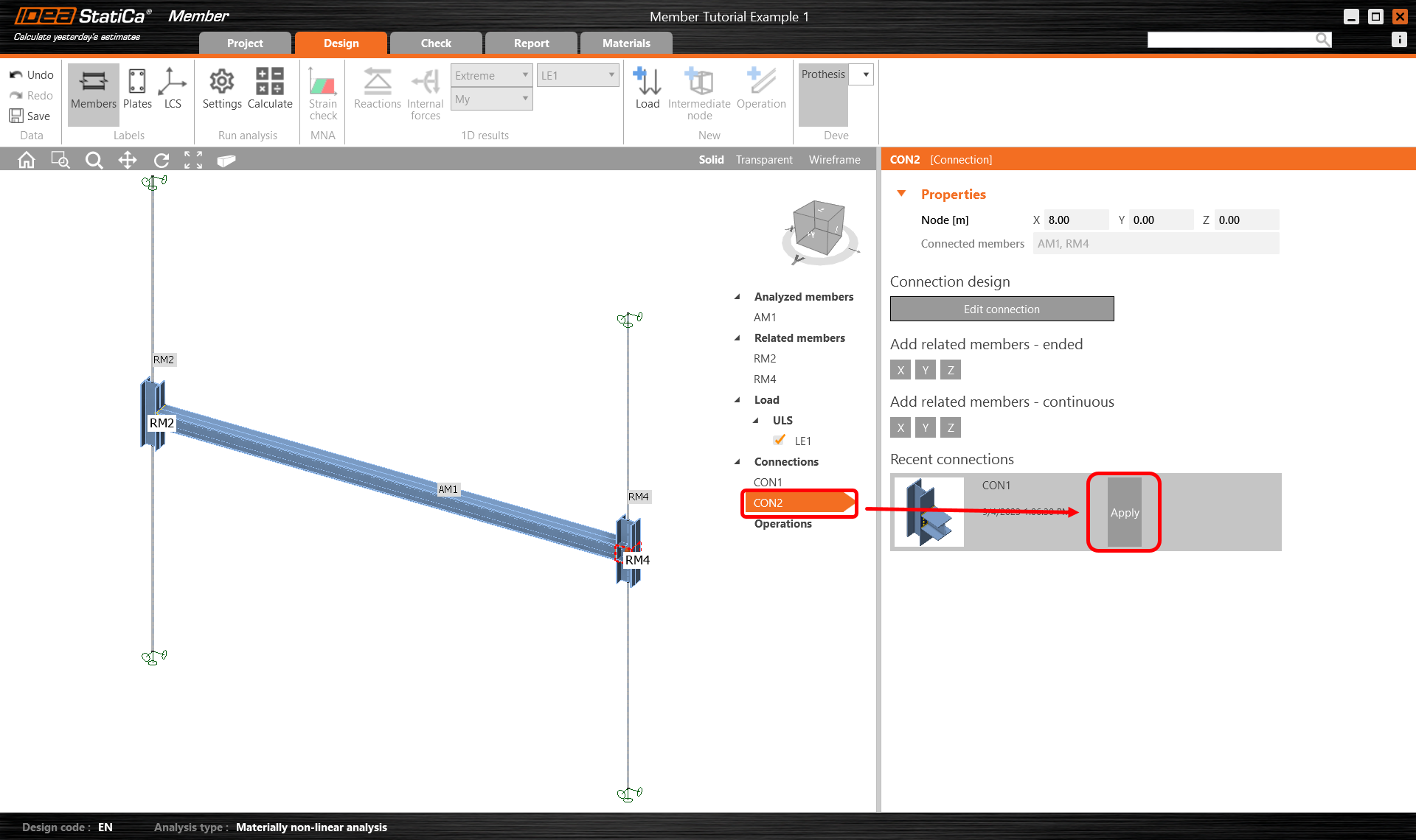
To design the second supported joint, click on Connections CON2 and then Apply the recent connection CON1.
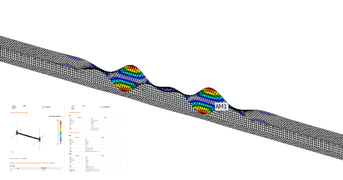
Check
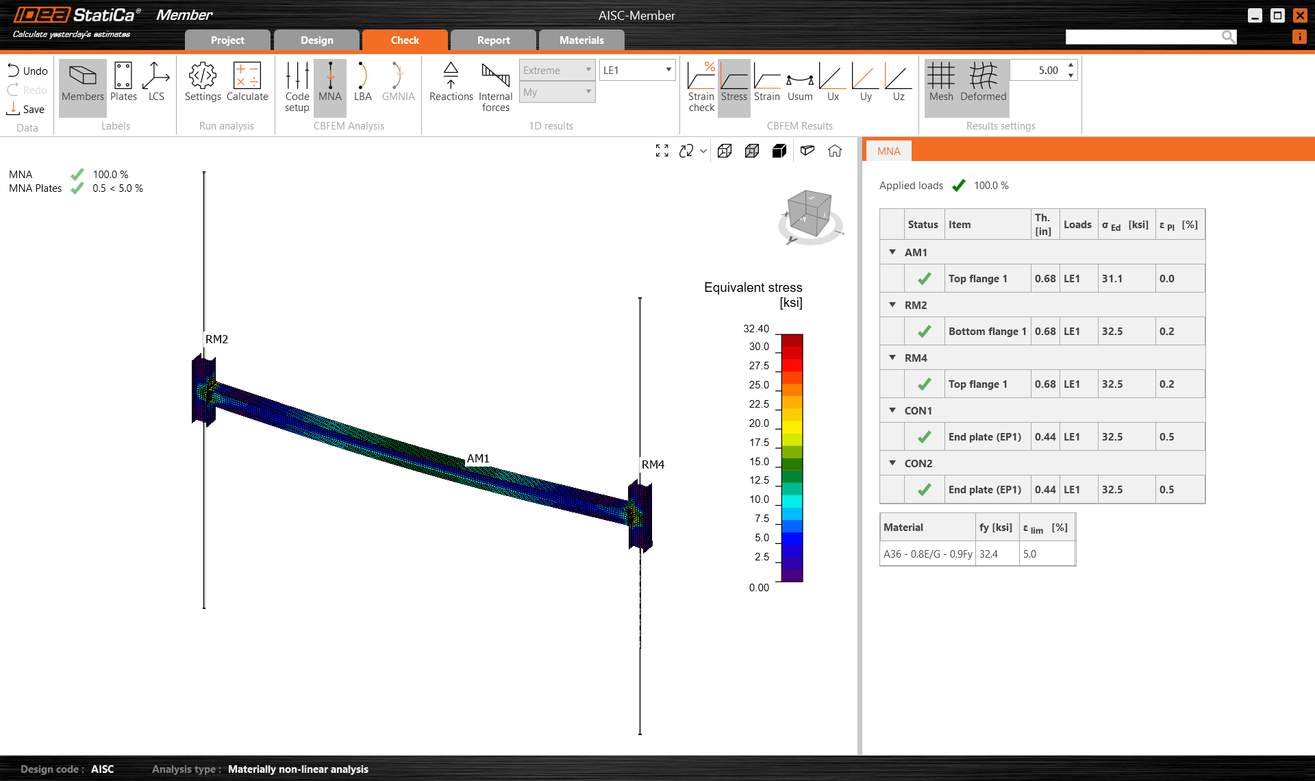
Now you can start the Materially non-linear analysis. Select the Tab Check, MNA, and click Calculate.
You can visually check the stresses along with the member by clicking on the button Stress in the upper ribbon.
Linear buckling analysis can be done by selecting LBA and clicking Calculate. You can investigate the mode shapes by clicking on a different line in the table.
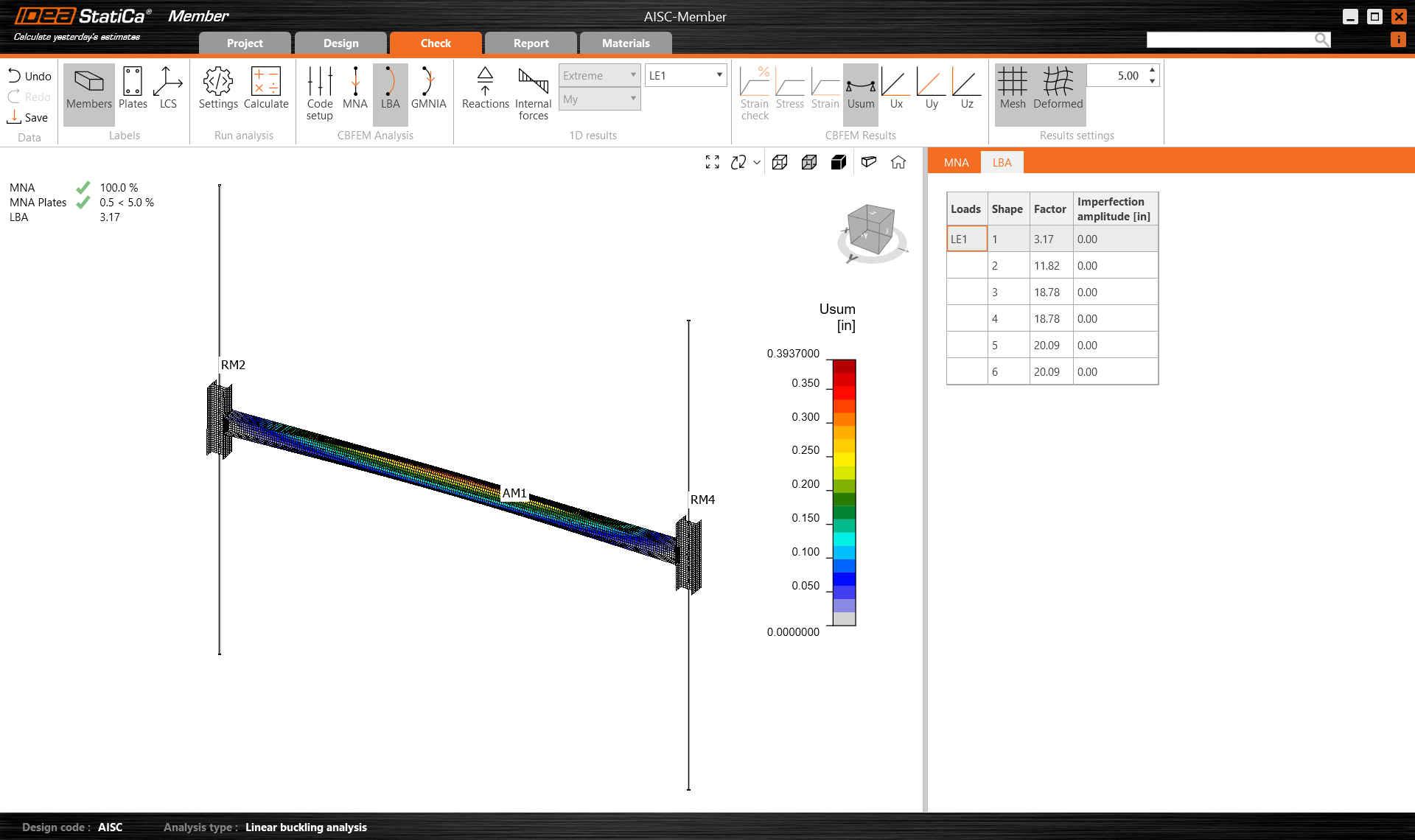
As you see the first two factors are less than 15, so in this case, a Geometrically and materially nonlinear analysis with imperfections makes sense with accumulated initial amplitudes. For more information please see the article about imperfections or the Theoretical background.
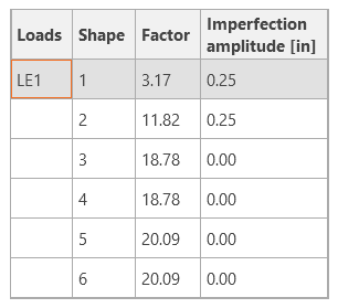
For the Geometrically and materially nonlinear analysis, you have to set the Amplitude (imperfection).
The eccentricities to be used are:
- L/1000 for beams - principally members in bending
- L/500 for columns - principally members under compression
We enter the value: L/1000 = 24x12 / 1000 = 1/4" (say)
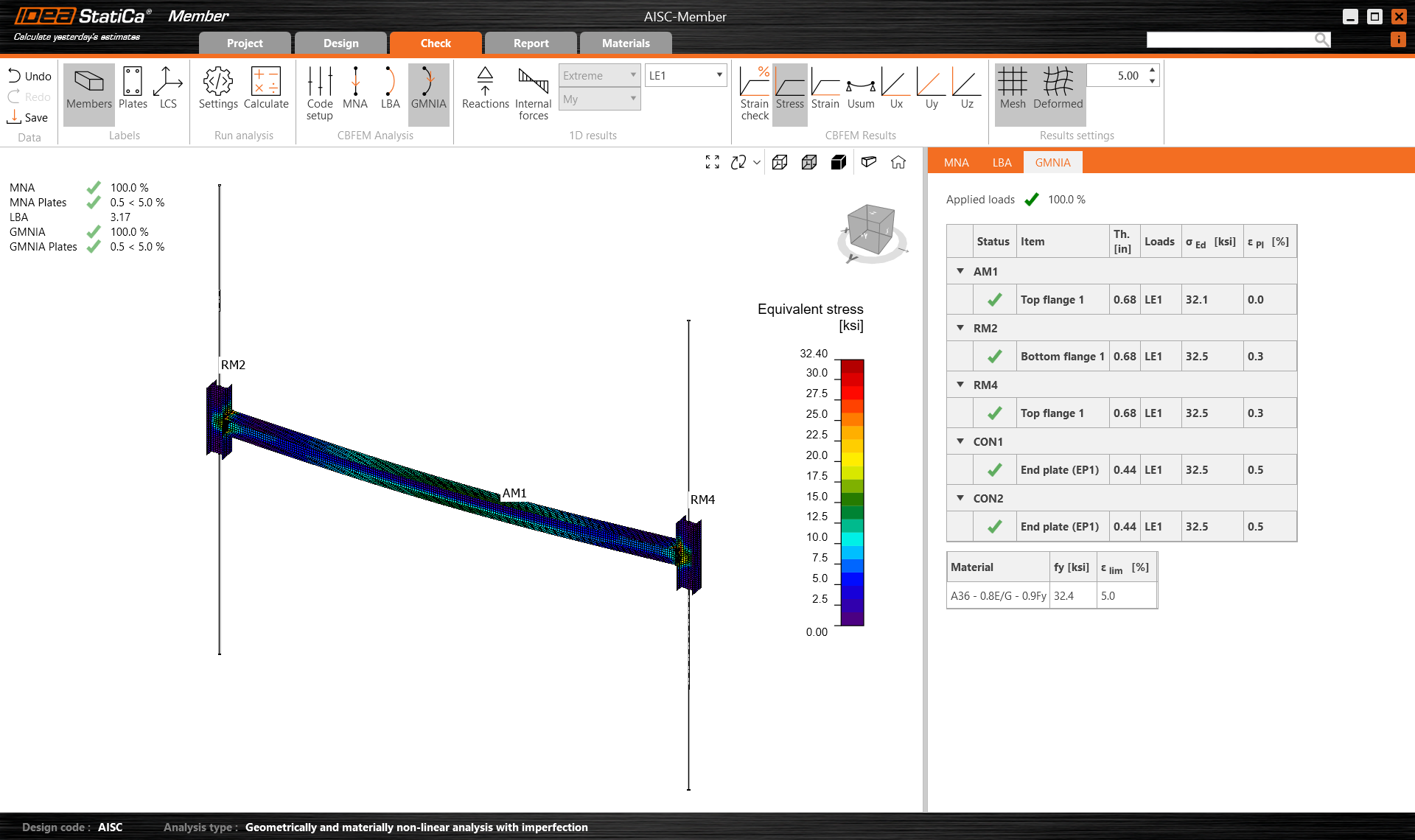
You can start the calculation by selecting GMNIA a click Calculate.
You can see in the results, that the dimension of the member is sufficient even with the geometrical imperfections.
Report
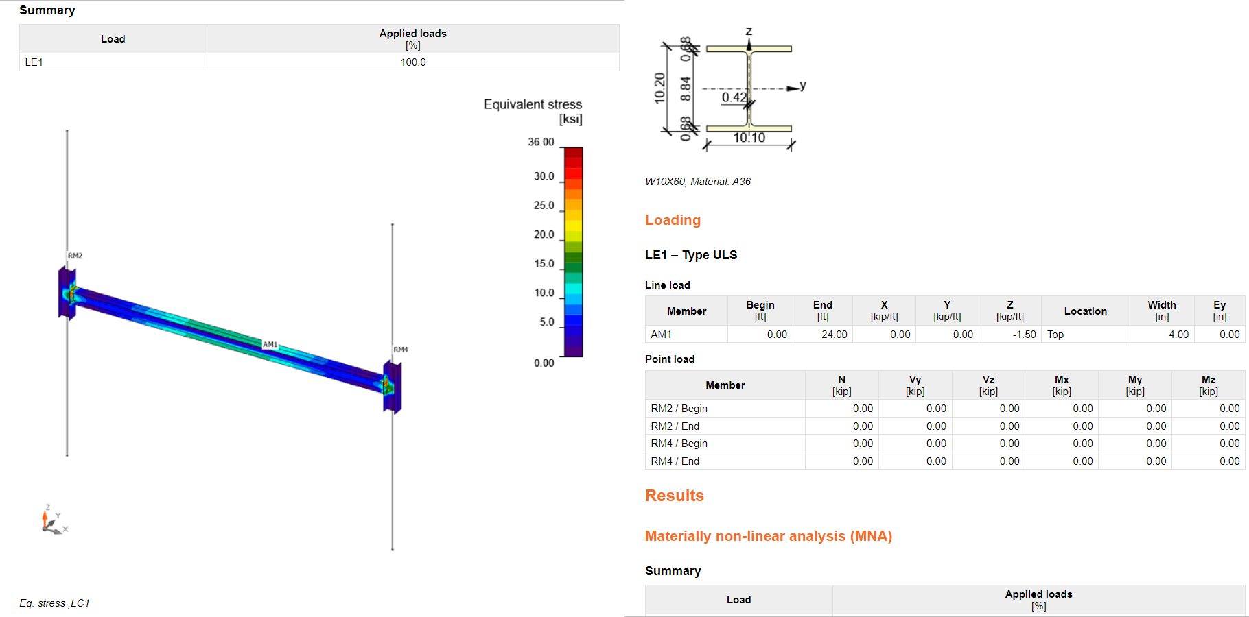
At last, go to the tab Report. IDEA StatiCa offers a fully customizable report to print out or save in an editable format.
Want to improve your skills? Visit our Campus
Attached Downloads
- Steel_AISC.csv (CSV, 645 B)
- AISC-Member.zip (ZIP, 32.2 MB)