
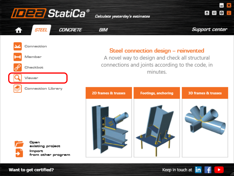
The UI of the IDEA StatiCa Viewer tool
You can find even more comprehensive information about the possible workflows with the Viewer tool in Project Viewer – useful and costless article.
How does it work?
A user can access the Viewer tool either in the browser at the URL viewer.ideastatica.com or from the Launcher app, or directly upload connection models from the Connection and Checkbot applications.
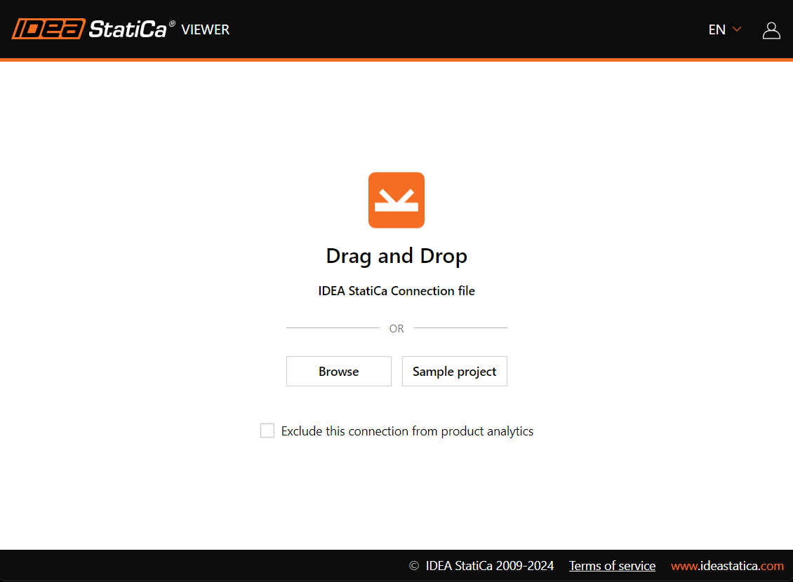
If the first option is used, the initial screen offers several options:
- Drag and Drop – for already existing model files
- Browse – for opening the project file from a hard drive
- Sample project – for opening a Demo project file with different types of connections
After dropping the model into an Internet browser window, the 3D scene shows all the components of the connection model. If users want to share the link, export the model as a DWG or IFC, or simply browse through the detailed information about the model's components, they need to be signed in.

If a current IDEA StatiCa account hasn't been created yet, it is sufficient to create a free Basic account according to this simple guided process.
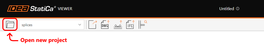
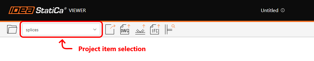
The top ribbon offers several essential options
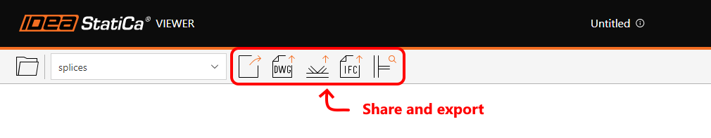
Exporting options in Viewer
- Share: One of the easiest ways to share the model information is to use the URL link directly to the Viewer web page with the model already uploaded. This button copies the URL link, which will be stored on the cloud server permanently, so the link can be kept and referred to in the designers' communication for the whole length of the project.
- Export to 3D DWG: Exports the 3D model in DWG file format with solid 3D elements and breaks down all plates into separate 2D line blocks.
- Export to IDEA StatiCa: This option creates and downloads the model in .ideaCon file format according to the current IDEA StatiCa version.
- Export to IFC: Exports the 3D model in IFC (Industry Foundation Class) file format.
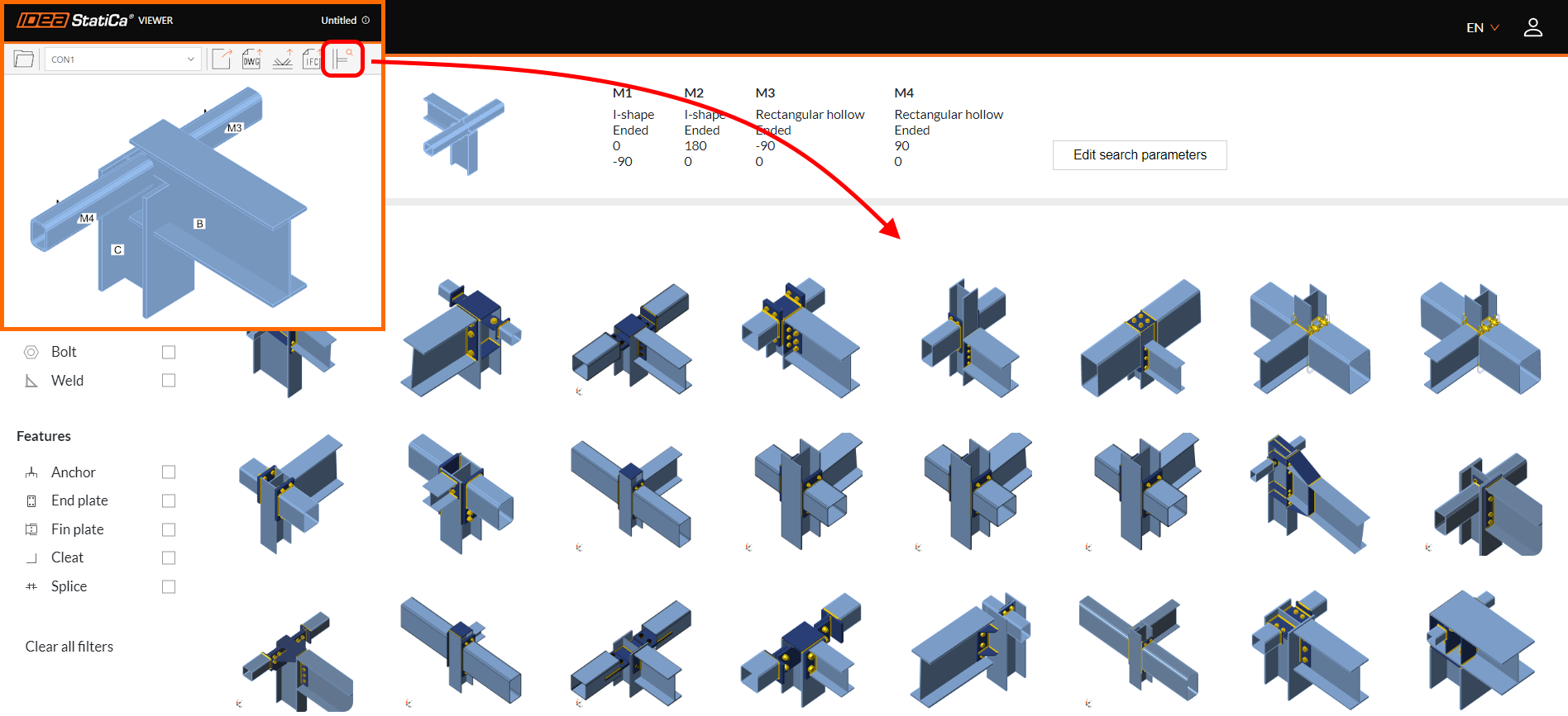
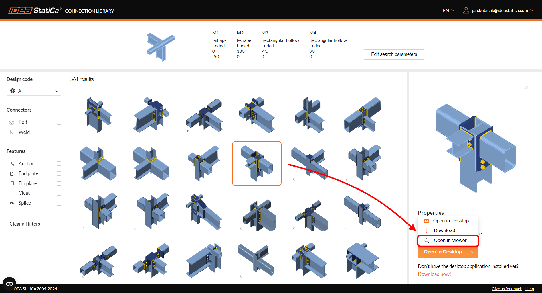
- Explore in Connection Library: This option launches the IDEA StatiCa Connection Library web page and offers hundreds of possible alternatives to the current arrangement. The filtering in Connection Library is preset according to the arrangement of the currently opened model in Viewer. The arrangement follows the number of members and their geometry with specific cross-section types.
After finding a valid connection design solution, the user can open the specific design back in the Viewer tool.
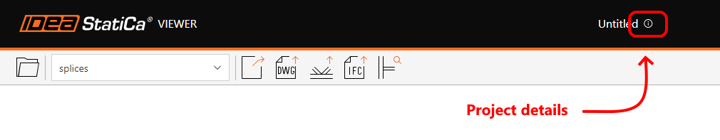
Besides these options, the project parameters can be displayed by clicking the info button at the top of the browser window.
Additional model properties

The inclusion of parametric templates in the Connection Library represents a significant advancement in the design process for connection designers. This functionality simplifies the design process by providing:
- Language selection: Two options are available – (EN) English and (CZ) Czech
- Units: Switching between Metric and Imperial units is available
- User login: Link management and Sign-in/Sign-out.
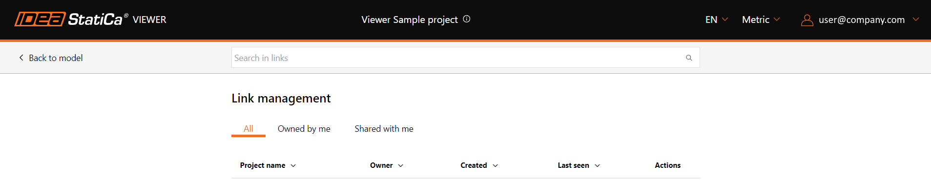
Link management

This tool provides the management of used URL hyperlinks. Users can browse through their own links or the ones shared with them. There is also an option to delete obsolete links (in Actions) that are not useful anymore.
The Property panel
In the right part of the screen, a whole set of model parameters is stored.
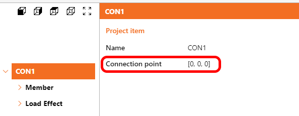
Connection space coordinates
After selecting the connection name (Project item) in the tree, two parameters are displayed: the Name of the item and the Connection point.
These coordinates indicate what is the spatial position of the connection node. For models created from scratch in the Connection application, the position will be zero in all directions. However, for models coming from the Checkbot application, the values will follow the spatial position of the node within the whole structure.
Load Effects
Besides information about the component materials and sizes, unique and important information about how the connection is loaded can be found under 'Load Effects'.
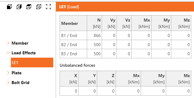
Together with load values, other crucial design information is also visible: Model type and Force position.
Weld properties
The right panel also contains information about the weld type:
- fillet (single/double-sided)
- butt weld
- partial joint penetration
with visual representation in the 3D scene also for:
- continuous
- partial length
- intermittent welds
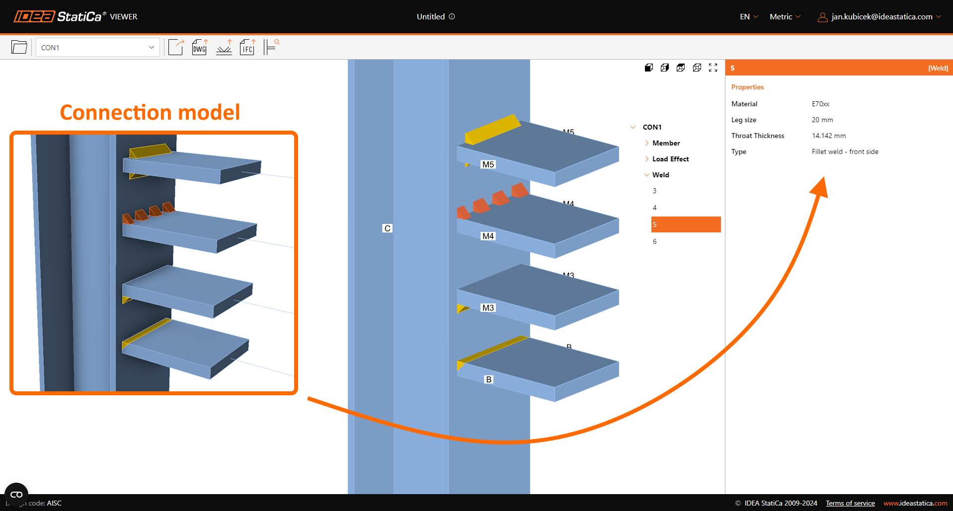
For clarity of outcomes, both values of weld size are displayed at the same time – Leg size and Throat thickness, independent of the units selected.
Connector properties
Additional information is displayed for different connector types:
Pins:
- Material
- Diameter
Anchors:
- Anchor name
- Diameter
- Anchoring length
- Shear plane in thread
- Anchor type
- Washer size
Bolts:
- Bolt assembly name
- Diameter
- Shear plane in thread
- Shear force transfer type
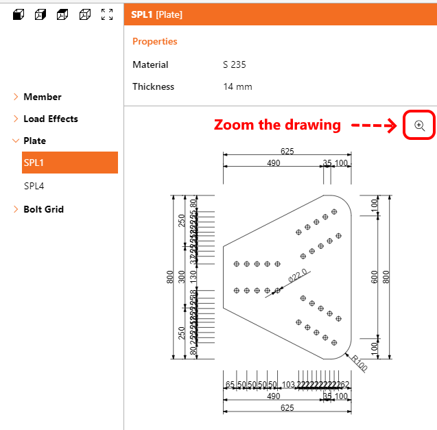
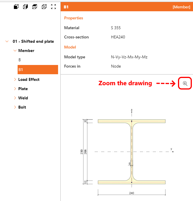
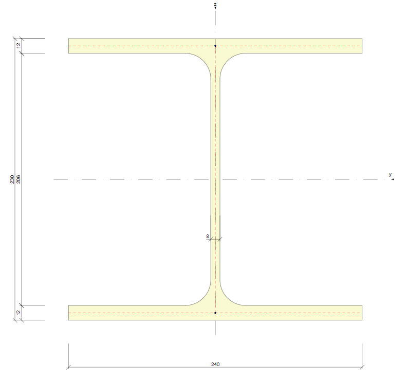
Element detail drawing
Detailed drawings of specific cross-sections and plates are displayed in an additional graphics window with their basic dimensions. For profiles and models with more complex plate shapes and overly dense dimension lines, there is an additional option to open an enlarged vector drawing in a new sub-window.
Released with IDEA StatiCa 24.1.
Foundation block
The navigation tree category – 'Foundation block' – provides information about anchoring parameters and material properties considered in the design.
Once the project model contains a concrete block, the following list of information is displayed:
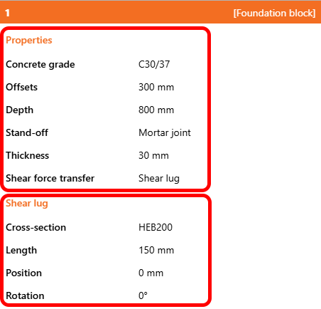
If the Shear force transfer is set to 'Shear lug', these parameters are also provided.
Response time of Viewer
Together with new model information, version 25.0 brings a huge reduction in response time, mainly with more complex models. In comparison to version 24.1, the model is uploaded and ready to work 2x faster, while the properties data are available 15x faster, which means a model is ready for investigation in seconds.
Released with IDEA StatiCa 25.0.