Access Ramps To Road Tunnel
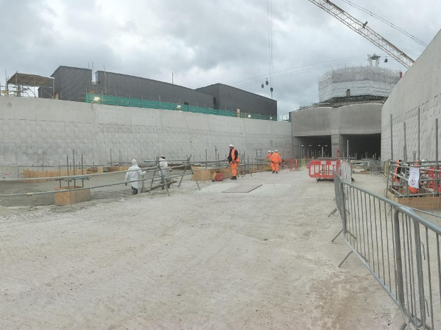
The acces ramps are part of a new road tunnel, which is a significant infrastructure project in the UK. The main aim of the tunnel is to reduce traffic jams in the nearby area, which is often very heavily congested, and to provide a more reliable river crossing for motorists. It's ready to enhance transport efficiency and speed up regional economic growth. The tunnel runs beneath the River Thames, connecting the south and north sides.
About the project
IDEA StatiCa Detail was used to evaluate the capacity of the retaining walls for the ramps that provide access to the tunnel on both sides of the river.
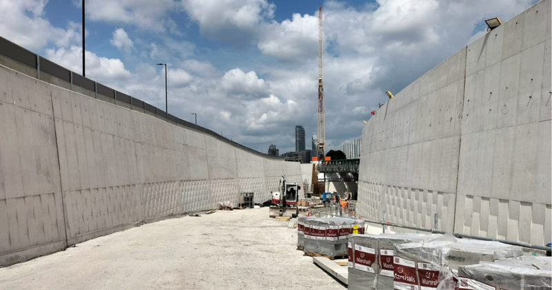
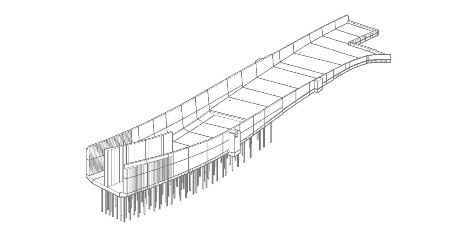
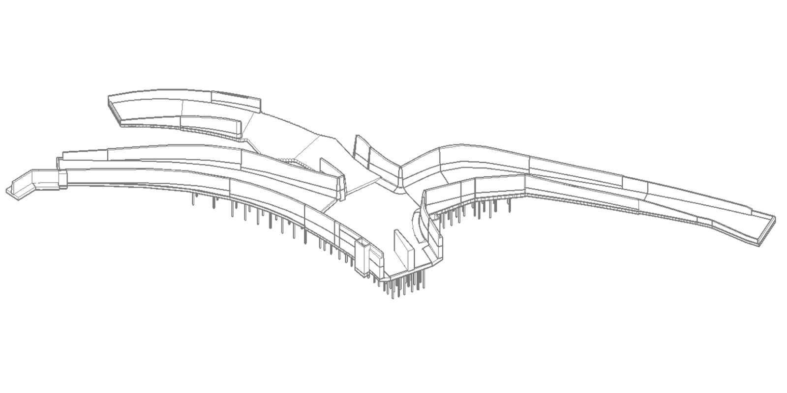
The ramp structure is an inverted U-shaped reinforced concrete form consisting of a bottom slab and two retaining walls. The bottom slab is connected to a series of micro piles in the deepest areas to ensure the structure's stability against soil consolidation. The temporary works for its construction involved a temporary excavation supported by sheet piles and struts, allowing the permanent structure to be built in several phases.
The earth pressure is derived from a 2D Plaxis model that incorporates the construction process of the permanent wall, including multiple phases of excavation and temporary support installation and phases of temporary support removal and permanent structure execution. This model enables the temporary and permanent analysis of earth pressure and design forces on the structure throughout each design phase.
Engineering challenges
The walls were designed and reinforced exclusively considering the effects of earth pressure and additional variable loads during the different construction stages.
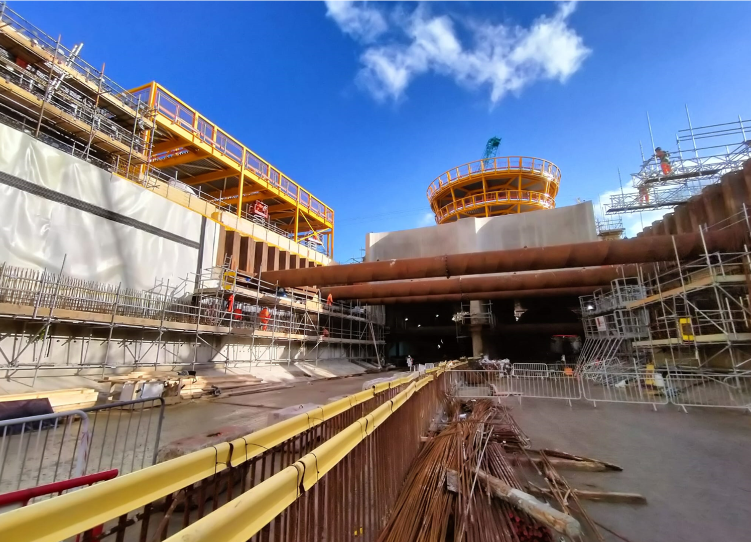
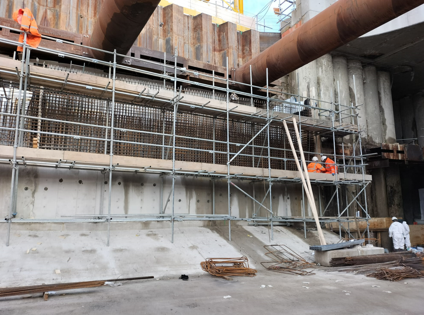
Given the walls' size and the excavation's depth, it became necessary to construct them in multiple phases. To facilitate this phased approach, it was decided to use formwork supported by the previously constructed wall part to withstand the forces that occurred during subsequent phases.
Therefore, during construction, the walls must bear the loads imposed by the formwork for subsequent wall phases. These formworks were also additionally supported by temporary sheet piles, which undergo deformation due to the construction load, transmitting a horizontal point load to the wall at their support points. These additional forces were significant. Therefore, verification of designed reinforcement was necessary.
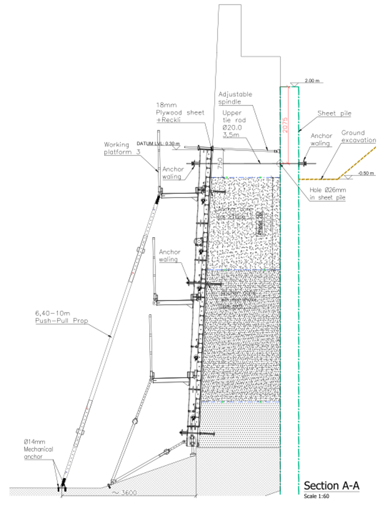
Also, during construction, the formwork designer did not respect the heights of the design construction joints. This modification in level caused the design assumptions to change, leading to deformations in the sheet piles and, consequently, increasing the loads transmitted by them to the permanent wall during the phase of temporary support removal.
Solutions and results
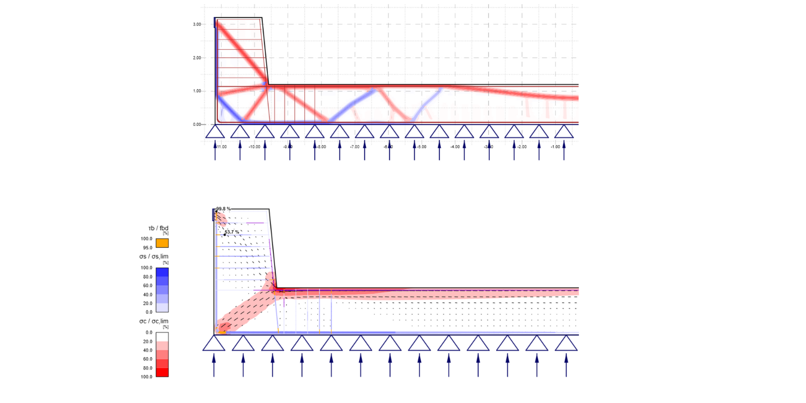
Therefore, verifying that the walls could resist the increased loads using the designated reinforcement became essential. IDEA StatiCa Detail was used for these additional calculations to provide code checks and obtain the structure's behavior. The team took advantage of the possibility of more precise results for the nonlinear solution, as at this stage, modification of the structure (e.g., adding extra reinforcement) would be very tedious and costly.
Spain
Their point of interest was, in particular, the joint between the retaining wall and the bottom slab of the access ramp. A more accurate calculation of the wall embedment and formwork anchorage area was performed, allowing the connecting and tie rods model in this area to be fine-tuned. Thus, it was verified that the longitudinal reinforcement could withstand the additional loading.
About Ayesa
Ayesa is a company with a broad scope of operations that extends beyond engineering into multiple sectors. Within the engineering domain, Ayesa manages an array of projects, demonstrating its versatility and expertise. These projects encompass various types, such as metro stations, dams, and viaducts, among others. This diversity in project types underscores Ayesa’s capability to handle complex and varied engineering challenges, further solidifying its reputation as a leader in the industry.
Try IDEA StatiCa for free