Lateral stability of long prestressed concrete beams during lifting
The lifting of long prestressed concrete beams is the first of the construction phases during which stability can be lost by a mechanism called lateral torsional buckling. On the designer's side, the elements are usually assessed for lateral stability on the completed structure, which is not always a critical condition, especially since the beams tend to be stabilized by the transverse elements, the floor, or the roof itself. Stability issues during construction are left to fabricators and contractors. The lateral buckling formulas found in many textbooks are not general enough for today's needs and thus fail to cover the demands of the modern fabricator, who is being pushed, especially by time and material prices.
In this verification paper, we compare the results from IDEA StatiCa Beam and its module for transverse stability calculation with the analytical calculation elaborated by Robert F. Mast 1989 [1] and Robert F. Mast 1993 [2]. In the first part of the text, we introduce the analytical method in brief and present a complete sample calculation for one load case, including all formulas and intermediate calculations. We then compare this with the result from the application and finally give a summary of several design situations.
Basic theory of roll equilibrium
When a beam hangs from flexible supports such as a lifting loop, it is free to roll. The center of rotation is the point at which the flexible support joins the rigid body. A line passing through the center of rotation at each support forms a roll axis. The initial eccentricity ei and offset of the hinges will always place the center of gravity slightly off the roll axis. This causes the beam to tip about the roll axis by a small angle θi.
\[\theta_{i}=tan\left(\frac{e_{i}}{y_{r}}\right)≈\frac{e_{i}}{y_{r}}\]
This slight tipping causes the component of the beam weight W sinθi to be applied in the direction of the weak axis. The beam is then bent, it further shifts the center of gravity of the mass of the beam. This causes an increase in the roll angle θ, which increases the lateral load as well as deflection. This continues until equilibrium is reached at an angle θ slightly greater than θi, or until the transverse deflection is sufficient to destroy the beam.
\[ \textsf{\textit{\footnotesize{Fig. 1\qquad Beam free to roll and deflect laterally – perspective}}}\]
\[ \textsf{\textit{\footnotesize{Fig. 2\qquad Beam free to roll and deflect laterally – end view and equilibrium diagram}}}\]
The component of the self-weight acting about the weak axis W sinθi has caused an additional lateral deflection z of the center of gravity. To find the equilibrium angle θ, one must find z, but z is determined by the weight component W sinθ, which itself depends on θ.
The problem may be solved by first computing a theoretical (fictitious) deflection z0 of the center of gravity with the full weight applied about the weak axis. Then, because the weak axis component is W sinθ, z may be found as z=z0 sinθ. The midspan deflection of a uniformly loaded simple beam can be computed using the well-known formula:
\[\beta_{y}=\frac{5}{384}\frac{wl^{4}}{EI_{y}}\]
But βy is the maximum deflection of the arc of the beam, and we need z0, which is the distance of the center of gravity of the deflected arc of the beam. z0 is approximately 2/3 of βy. More precisely:
\[z_{0}=\frac{1}{120}\frac{wl^{4}}{EI_{y}}=0.64\beta_{y}\]
The derivation of this formula can be found in [1] Appendix F. The equilibrium equation can be then rewritten as:
\[tan\theta=\frac{z_{0}sin\theta+e_{i}}{y_{r}}\]
The only unknown is now θ, which may be found by successive approximation. Let's say for angles θ < 0.2 rad, the approximation θ ≈ sinθ ≈ tanθ may be used. The equilibrium equation then simplifies to:
\[\theta=\frac{e_{i}}{y_{r}-z_{0}}\]
Effect of lifting point location
Locating the lifting point even a small distance from the end can dramatically improve the lateral bending stability. Not only is the deflection reduced, by approximately a fourth power of the net span, but z0 is improved even further, as the weight in the overhanging ends is on the opposite side of the roll axis.
\[ \textsf{\textit{\footnotesize{Fig. 3\qquad Computation of z0 including overhanging ends}}}\]
The equation for z0 was obtained by integrating the shape of the deflection curve to find its centroid.
\[z_{0}=\frac{w}{12EI_{y}l}\left( \frac{1}{10}l_{1}^{5}-a^{2}l_{1}^{3}+3a^{4}l_{1}+\frac{6}{5}a^{5} \right)\]
Example for comparison
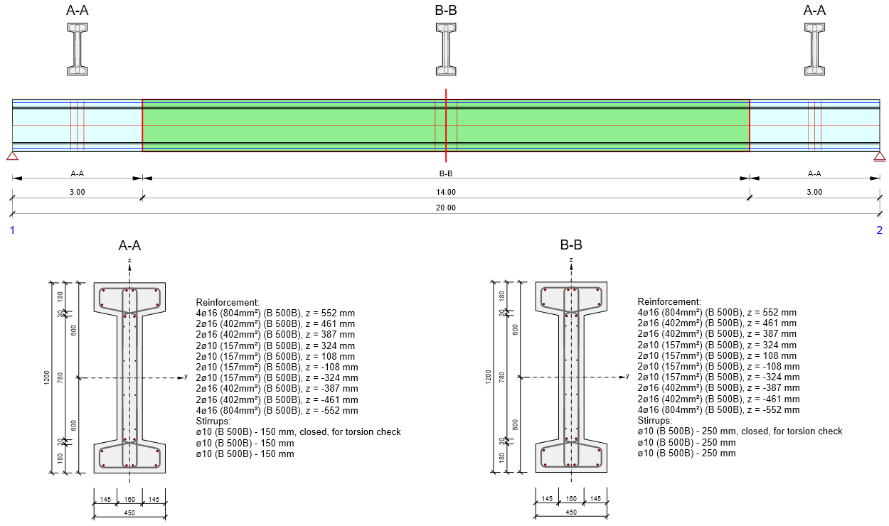
The purpose of this paper is to demonstrate the correctness of transverse stability calculations in IDEA StatiCa Beam for the case of beam lifting. It is worth noting that the same geometrically and materially non-linear solver is used for all design situations, only the boundary conditions or the initial condition is changed. As an example to compare the results with the analytical method presented above, a prismatic beam of I-section, centrically pre-tensioned such that the normal force is approximately Np = 1600 kN, was chosen. The beam is further reinforced with B500B concrete reinforcement as shown and is made of C40/50 concrete. The prestressing is chosen so that no cracking occurs for any condition under test.
A bi-linear stress-strain design diagram is used for the analysis in the application, where it is possible to simply determine the modulus of elasticity for the elastic branch Ecd=fcd/εc3.
\[ \textsf{\textit{\footnotesize{Fig. 4\qquad Perspective view of the beam under examination}}}\]
\[ \textsf{\textit{\footnotesize{Fig. 5\qquad Geometry and reinforcement}}}\]
Please note that the axes are labeled differently in Figure 5 than in the previous theoretical introduction, where the labeling was based on [1] and [2]
The beam will be suspended by hooks with height hh = 150 mm. This means that yr = 0.5h + hh = 600 + 150 = 750 mm.
Analytical calculation
The calculation principle has already been mentioned at the beginning of this article. Now we will take a detailed look at one of the design situations and compare it with the result from the application. The hinges will be placed at a = 1.0 m and the initial eccentricity will be eig = 350 mm. This is the geometric initial eccentricity of the deformed beam, meant as the maximum deflection of the arc. It is, therefore, not the initial eccentricity of the center of gravity from the roll axis ei that is used in the manual calculations above. For practical reasons, the eig value is used as an input to the IDEA StatiCa Beam application. For all cases considered, the eig value was converted to the ei value using the graphical method in the CAD application.
\[ \textsf{\textit{\footnotesize{Fig. 6\qquad Non-iterative approach}}}\]
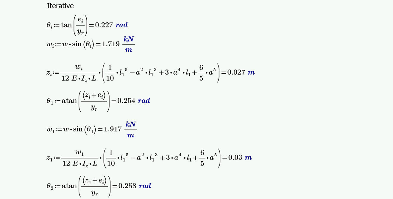
Now, since we got an angle θ > 0.2 rad, we will check the correctness of the results without using the above-mentioned approximation θ ≈ sinθ ≈ tanθ. We then have to proceed with the iterative calculation, where we first calculate the initial roll angle θi and continue iteratively until the calculation is stable.
\[ \textsf{\textit{\footnotesize{Fig. 7\qquad Iterative approach}}}\]
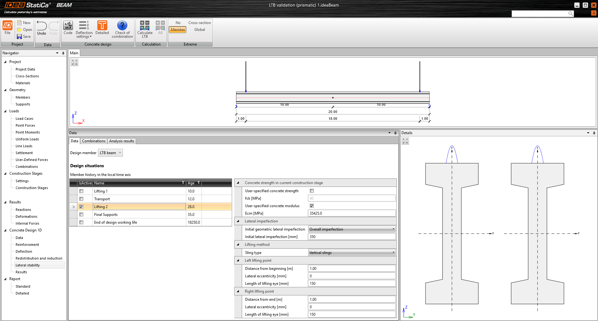
Now, let's see how the same task was calculated in IDEA StatiCa Beam and its Lateral stability module. The input values for the calculation are presented in Figure 8. The dynamic coefficient as well as the other combination coefficients are set to 1.0.
\[ \textsf{\textit{\footnotesize{Fig. 8\qquad Lateral stability data input}}}\]
IDEA StatiCa Beam results
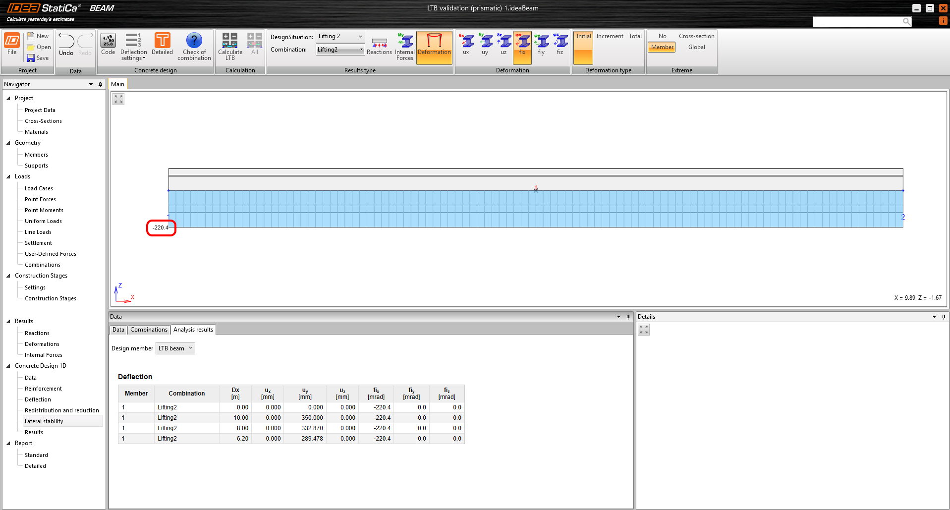
For verification purposes, we compare the beam rotation value because this value is the basic output of the solver. Other outputs, such as deformation and internal forces, are directly dependent and related to the beam rotation. First, we look at the initial rotation θinit = 220.4 mrad, which should correspond to the value of θi = 227 mrad from the analytical calculation.
\[ \textsf{\textit{\footnotesize{Fig. 9\qquad Initial rotation}}}\]
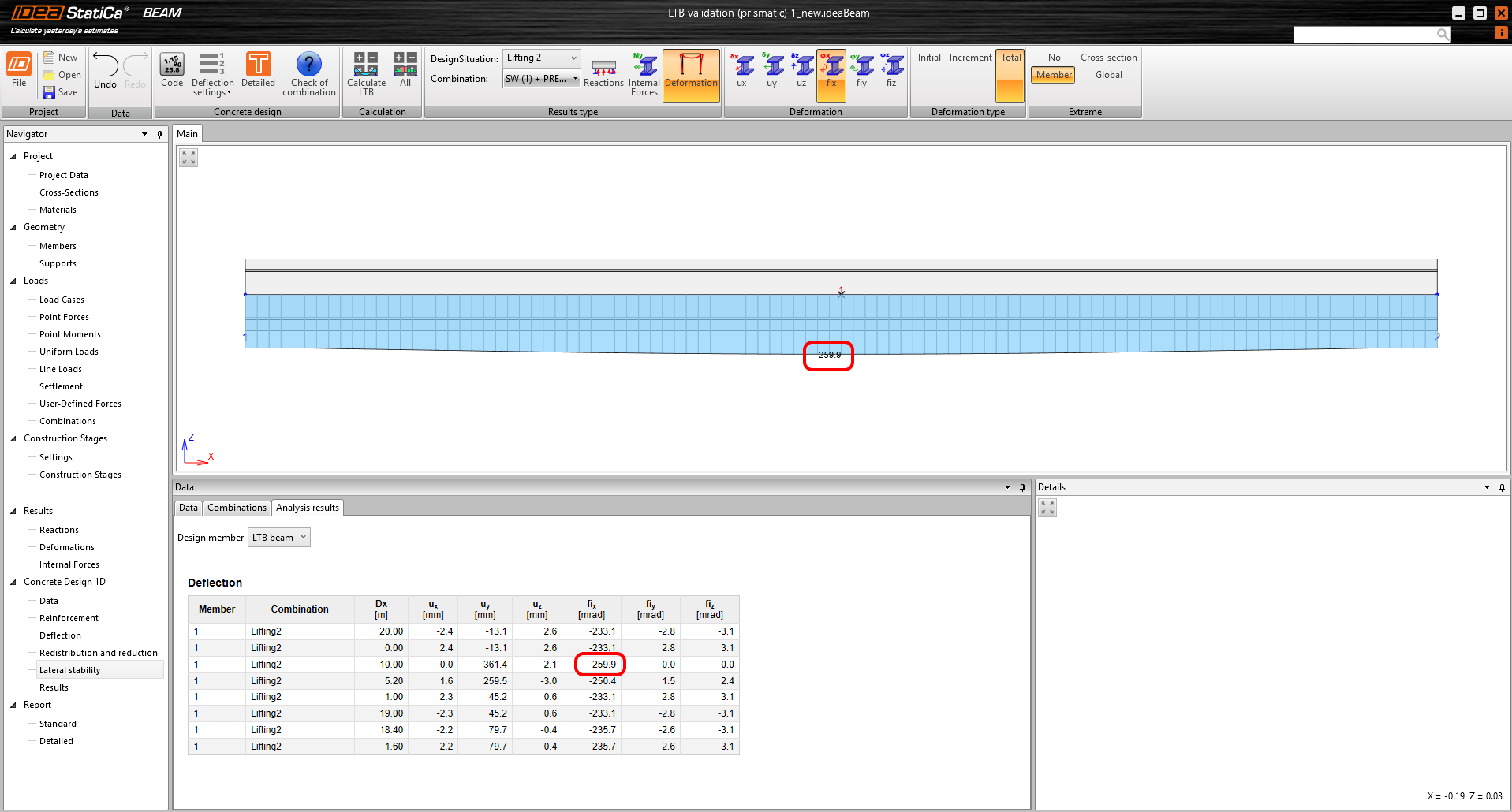
Finally, we can compare the results of the overall beam rotation, which can be seen in Figure 10. The values at both the beginning of the beam and at its center are highlighted. It is, therefore, possible to observe the effect of the rotational stiffness of the beam, which is not captured by the analytical calculation.
\[ \textsf{\textit{\footnotesize{Fig. 10\qquad Final rotation}}}\]
All examples
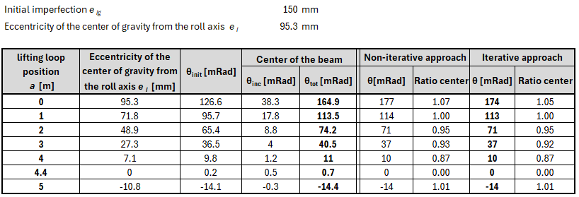
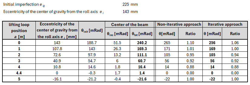
This chapter presents all the tested assignments for the studied beam with different combinations of initial imperfection and lifting loop positions.
θinit is the value of the initial rotation obtained from the application and should be compared with θi from the analytical calculation. θinc is the increment of rotation calculated in the application caused by the additional rotation caused by lateral deformation from self-weight and θtot in the resulting rotation compared with the θ value from the analytical calculation.
\[ \textsf{\textit{\footnotesize{Fig. 11\qquad Design situation 1}}}\]
\[ \textsf{\textit{\footnotesize{Fig. 12\qquad Design situation 2}}}\]
\[ \textsf{\textit{\footnotesize{Fig. 12\qquad Design situation 3}}}\]
Conclusion
In this paper, we compared the analytical calculations of the transverse stability of beams under the design scenario lifting according to [1] and [2] with the fully material and geometrically nonlinear FE analysis performed in IDEA StatiCa Beam. The results show that the more sophisticated analysis proved to be very accurate, reliable, and sufficiently precise. Due to its generality, it can also cover a significantly larger portfolio of design situations without simplification and tedious manual calculations. We can also observe at which position of the hinges the equilibrium position has been reached so that the beam does not rotate. In this state, the overhanging ends have a stabilizing moment equal to the destabilizing moment from the deflected of the beam.
References
[1] Mast, R. F. (1989). “Lateral Stability of Long Prestressed Concrete Beams, Part 1.” PCI J. 34(1), 34–53.
[2] Mast, R. F. (1993). “Lateral Stability of Long Prestressed Concrete Beams, Part 2.” PCI J., 38(1), 70–88.


