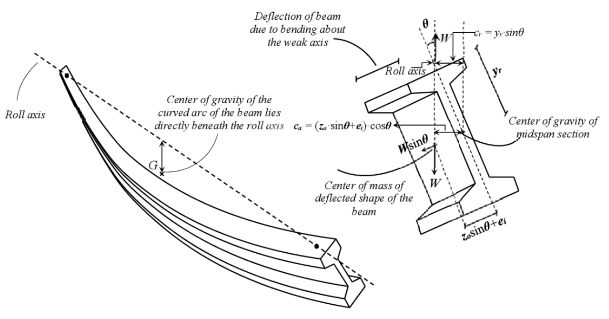
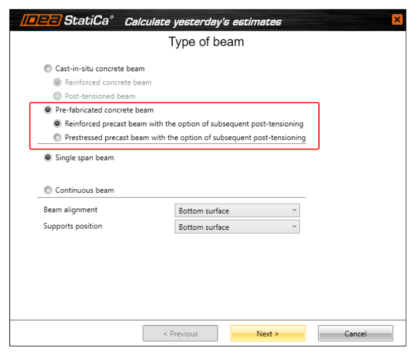
LTB is a stability failure that occurs in slender beams under bending, causing lateral displacement and twisting. It typically affects long and slender prefabricated beams. Checking for LTB is crucial to prevent sudden failure, optimize structural design, and ensure compliance with safety codes. It is essential to verify all construction stages, including lifting and transportation. The solution is suitable for any reinforced concrete and prestressed (pre-tensioned) pre-fabricated concrete beams.
The geometrically and materially non-linear calculation released in 24.1 can capture the mentioned effects and provide results of internal forces including second-order effects. Calculated internal forces for selected sections are now automatically collected and sent to RCS for detailed code-checks (available from version 25.0).
LTB
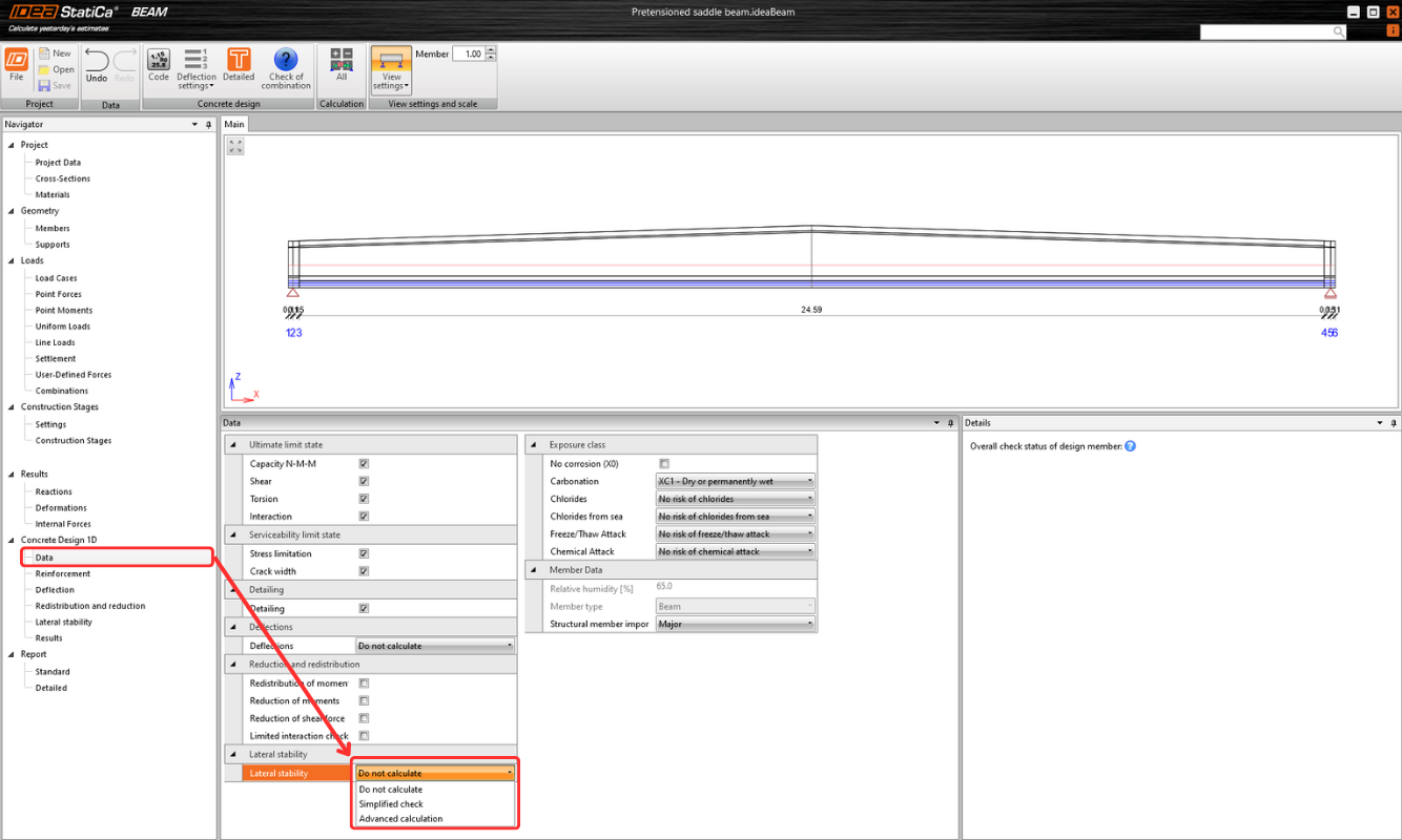
The option can be selected in the Design 1D – Data section next to the Simplified Check and Do Not Calculate options. All necessary input belongs to the Lateral Stability section. In the case of simplified verification, only the basic dimensions need to be entered. For advanced analysis, more detailed input is required, including construction history, imperfections, and other parameters.
Setting the analysis
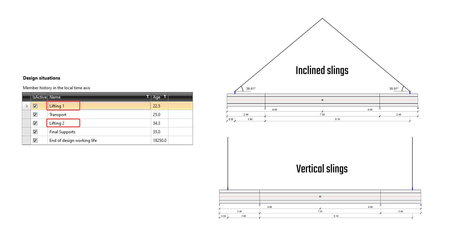
Construction stages
Each design situation requires specific inputs due to varying boundaries and times for the code-check. The times for each design situation can be set independently from the construction stages set at the beginning. Concrete properties, such as fck and Ecm, are automatically calculated based on the specified times but can be manually defined by the user if needed.
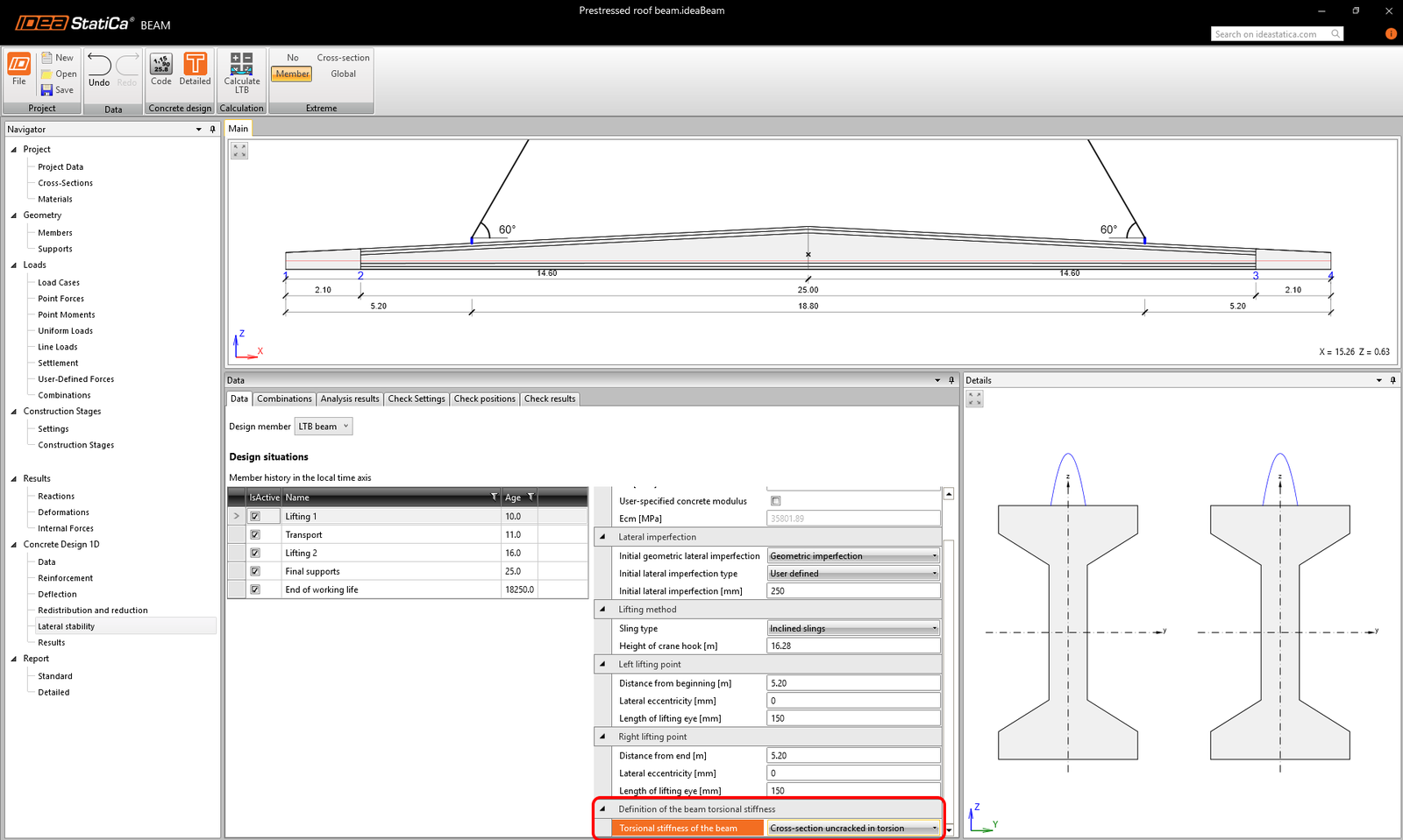
Torsional stiffness
In the setting, there is the option (since v25.1.) to define torsional stiffness more accurately. In the drop-down menu “Torsional stiffness of the beam”, whether the beam cross-section should be considered uncracked or cracked in torsion can be selected.
- Uncracked in torsion: torsional stiffness is calculated as the linear torsional stiffness of the reinforced concrete cross-section.
- Cracked in torsion: torsional stiffness accounts for the torsional resistance provided by longitudinal reinforcement (including prestressing), stirrups, and compression diagonals, safely neglecting the concrete contribution.
The setting can be applied separately for each Design situation, giving engineers flexibility to adapt the calculation approach depending on the limit state or load combination.
Recommendation for use: As a guideline, the option Uncracked in torsion is recommended for fully prestressed members where the decompression condition is satisfied. In contrast, for partially prestressed beams where, under ULS loading, the tensile stress in extreme fibers exceeds the design tensile strength of concrete (fctd), and for reinforced concrete members, we recommend switching to the more conservative Cracked in torsion assumption.
Imperfection
Also, the value of an initial lateral imperfection can be defined separately for each design situation. There are two options for the definition of lateral imperfection:
- Geometric imperfection – where IDEA StatiCa Beam calculates deformations due to creep and shrinkage. But first, the Initial imperfection needs to be set. It can be a) By code – imperfection is assumed according to EN 1992-1-1, chap. 5.9 (2) as L/300 or b) User-defined.
- Overall imperfection – resulting lateral imperfection has to be defined by user.
Inputs for lifting
Two types of lifting can be defined: vertical slings or inclined slings, each with specific calculation conditions. The position of the lifting points must be specified in both the longitudinal and transverse directions of the beam.
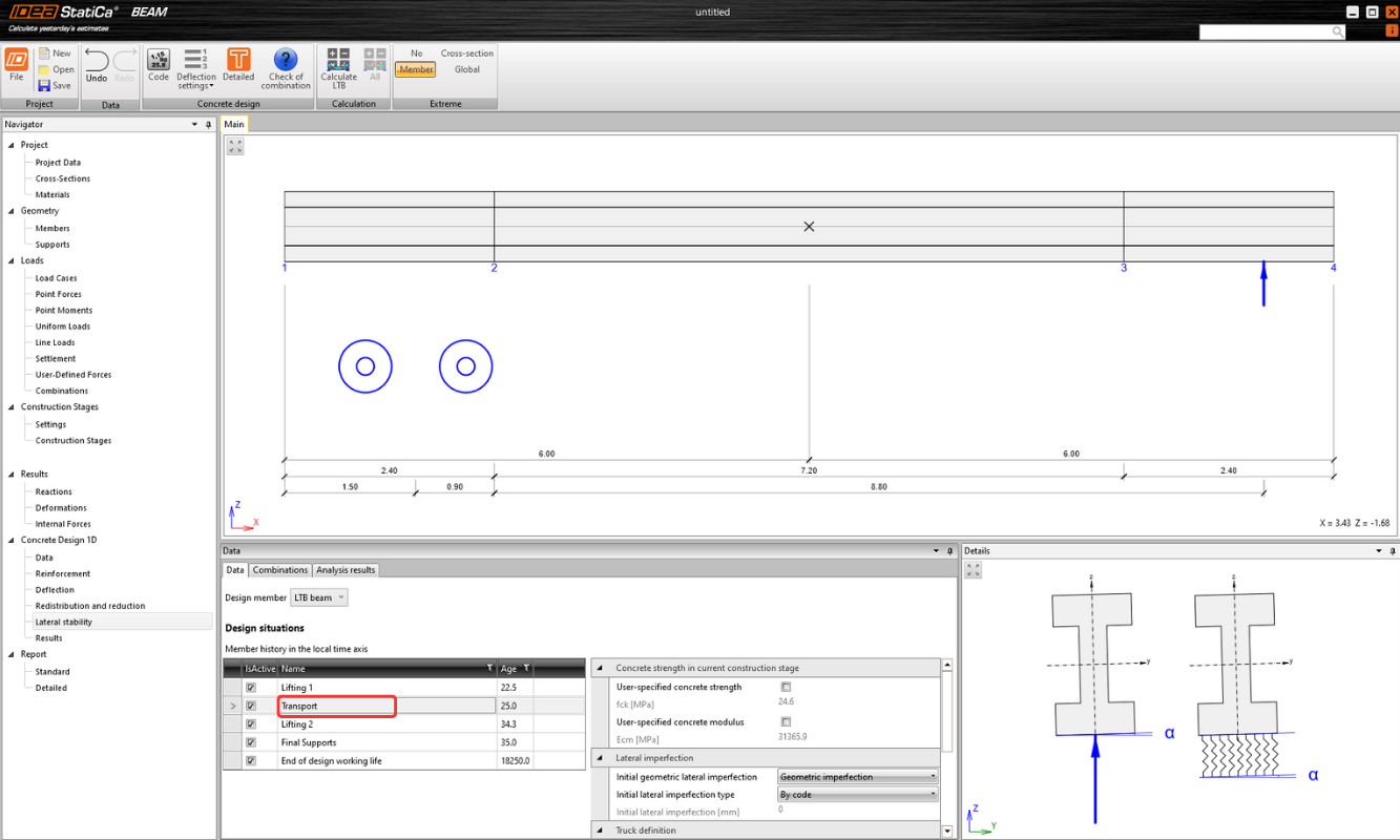
Inputs for transport
Transport refers to the scenario where the beam is loaded onto a truck with a trailer. Deformation in the Rx direction is restrained solely by the trailer and treated as flexible support with defined stiffness. The user needs to define parameters such as the position of the truck, properties of the trailers, and others.
Inputs for final supports and end-of-design working life
The static scheme for final supports and the end of the design working life is the same, with no option to define supports in the end-of-design working life scenario. The beam is always considered simply supported at its ends. Additionally, the beam can be laterally restrained at specified positions if desired.
Final supports are always positioned at the ends of the beam and can be represented by three types of support: Elastomeric bearings/Forks/Bearing pads with dowels.
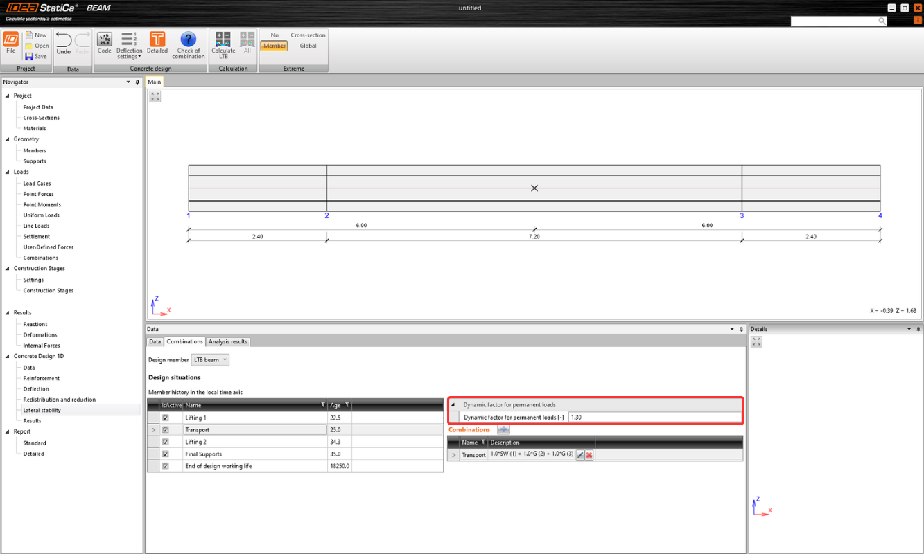
Loads
The "Loads" section in the tree of entities in previous design steps defines all the load cases, loads, and load factors. In the section Lateral Stability, dynamic factors for lifting and transport phases and correct non-linear ULS combinations for each Design situation must be defined.
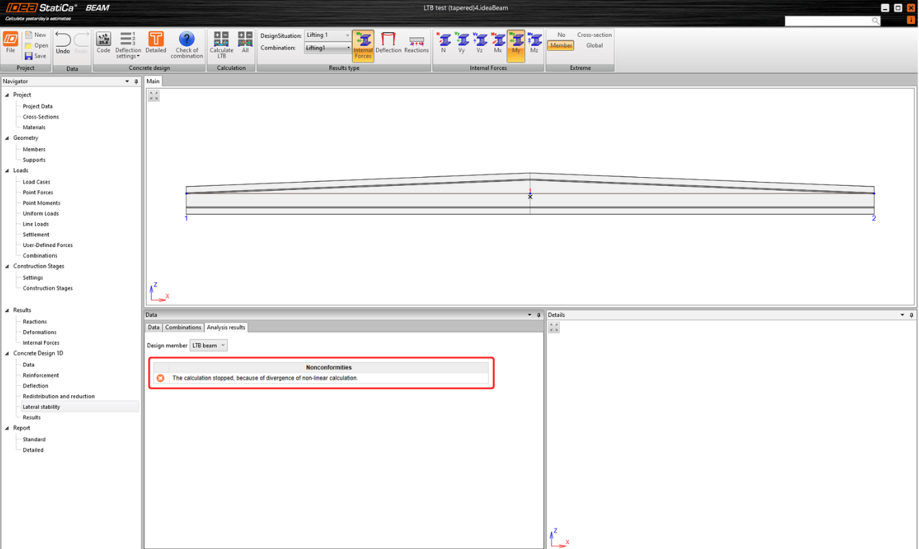
Results
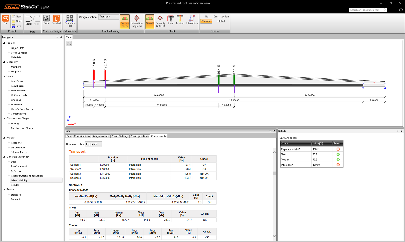
The advanced Lateral torsional buckling (LTB) analysis in IDEA StatiCa Beam provides (in addition to reactions, internal forces, and deformations) an evaluation of whether the beam is at risk of collapsing due to stability issues for each defined construction stage. In the event of a structural failure due to LTB, the calculation will not be complete, and the user will see an error message informing them of this situation.
The Check Settings tab allows you to define ULS code-check types for the selected member. In the Check Positions tab, you can specify multiple section locations where detailed code checks will be performed using RCS.
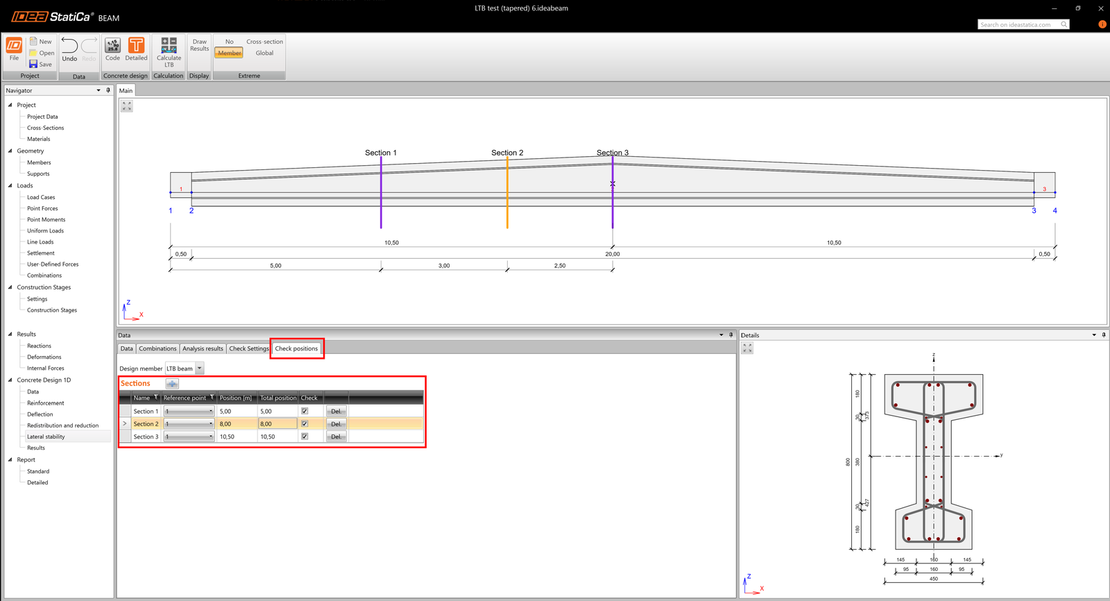
Detailed RCS checks for lateral stability are integrated directly in the Beam app (since v25.1).
Note
Please be aware that advanced LTB analysis only works for models created in v24.1 and higher. The calculation will not proceed for older projects, and they must be remodeled.
Released in IDEA StatiCa version 24.1, improved for detailed results and torsional stiffness definition in IDEA StatiCa version 25.1.