Buckling analysis of a steel connection (EN)
1 New project
Launch IDEA StatiCa (download the newest version) and select the Connection application.
Create a new project by selecting the starting template closest to the desired design. Fill in the name, select the steel grade S355, design code Eurocode, and Create project.
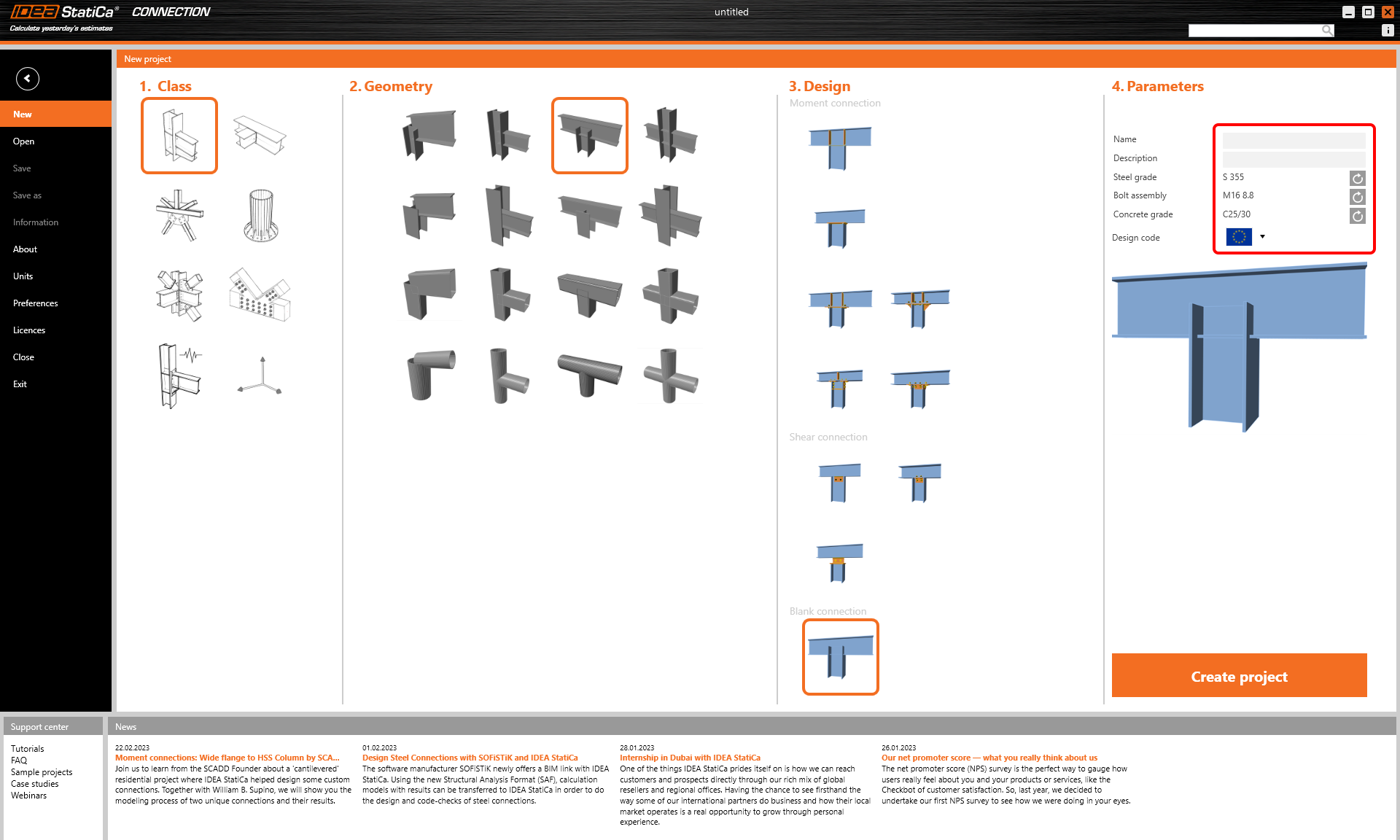
Since we are using the EN code, set the metric units (see How to change the system of units).
2 Geometry
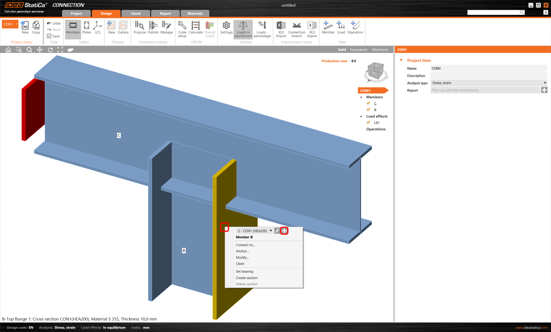
Start with the modification of the connection geometry. Right-click on the vertical member B and open the context menu with available actions. Use the Plus button to add a new cross-section.
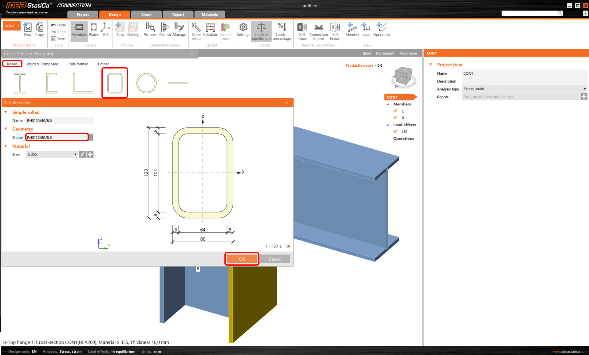
Choose the Rectangular hollow sections group and confirm the RHS120/80/8.0 type of cross-section.
Now, you can modify the properties of member B. Set the Model type to N-Vy-Vz and the parameter Forces in to Bolts.
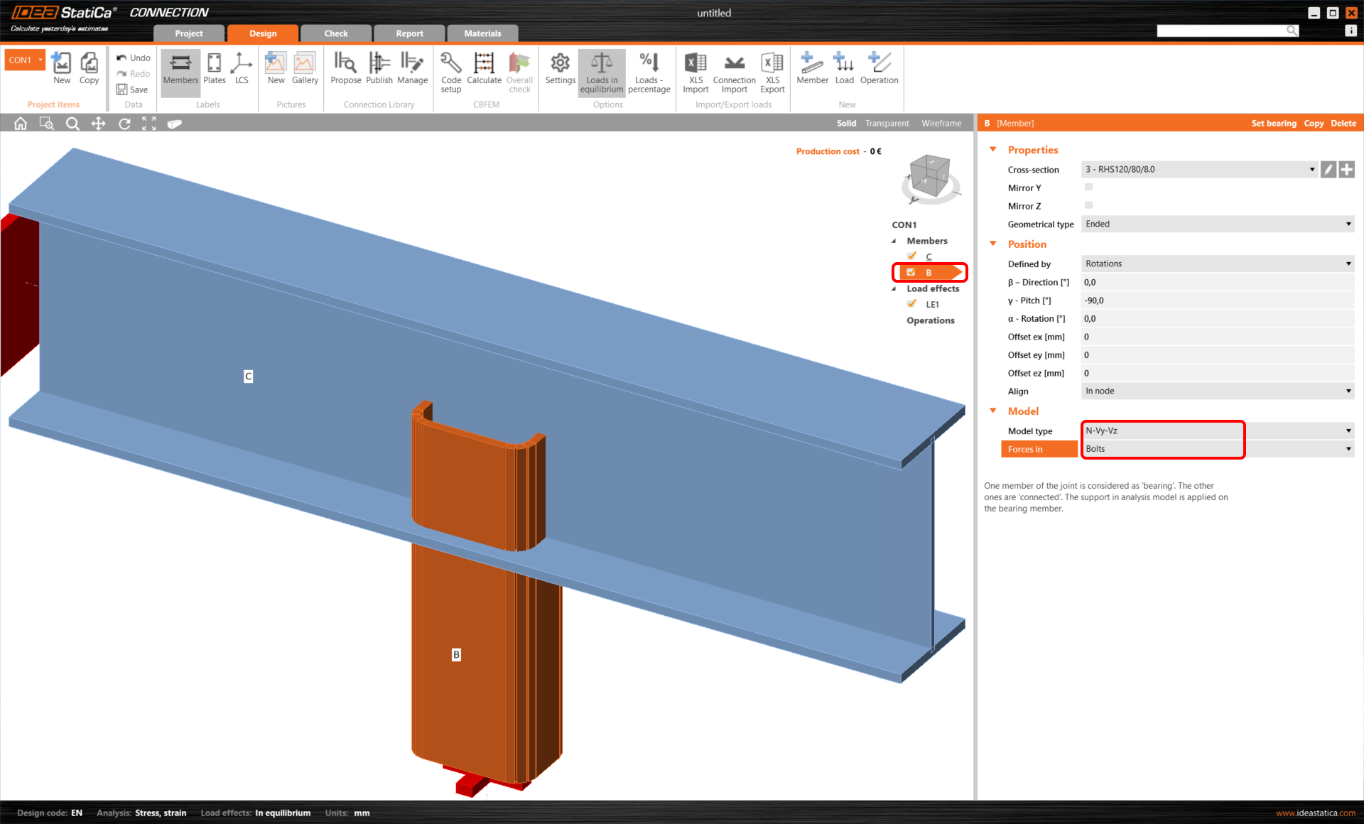
Read more about the Model type and Forces in parameters in How to model a single bolt connection (Model type) and How to define correct load position (Forces in) articles.
3 Load effects
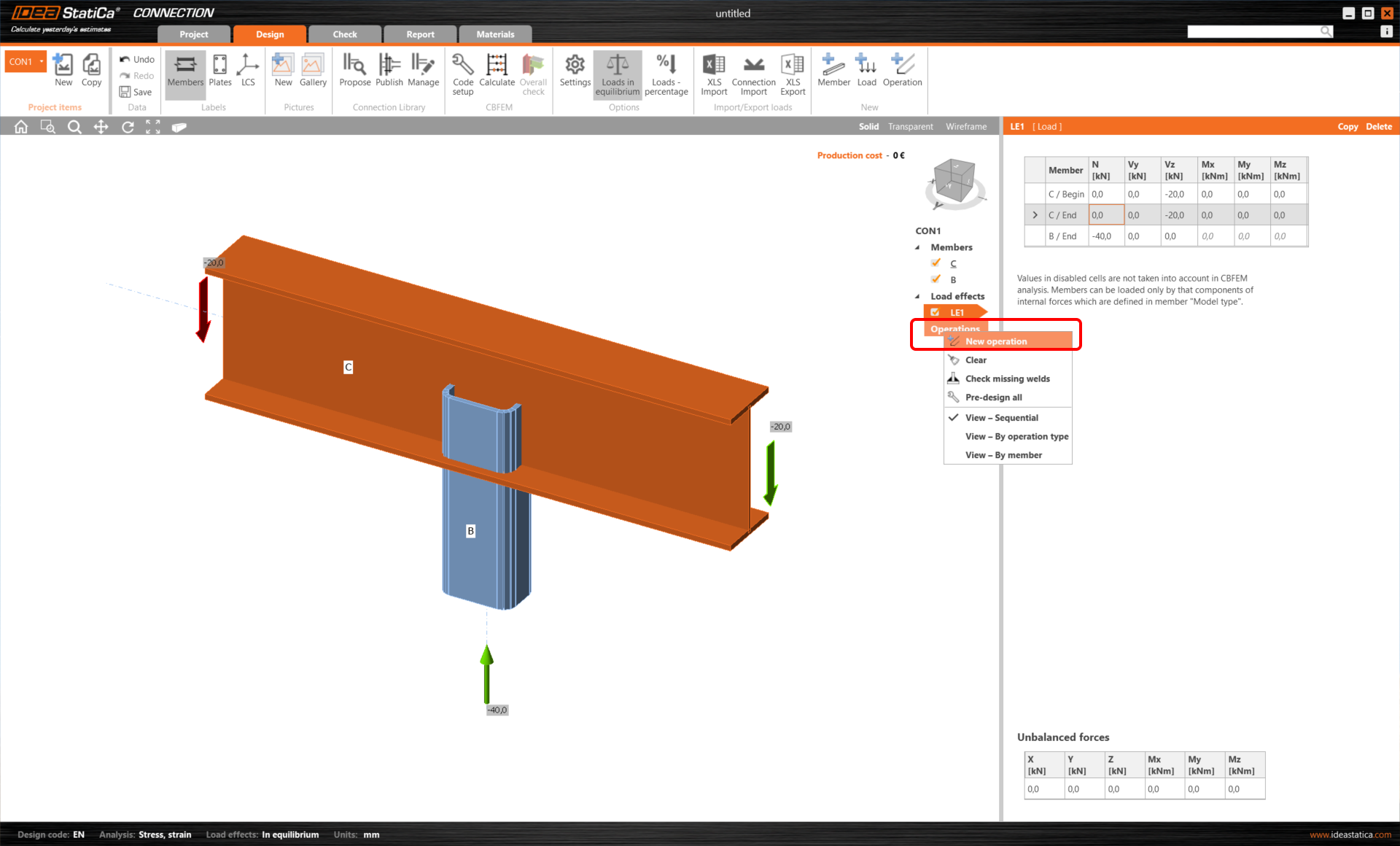
Let’s continue with the Load effects. Load effect LE1 was automatically added. Input -40 kN of normal force N [kN] for member B / End in the tab and -20 kN of shear force Vz [kN] for both ends of member C (C / Begin, C / End).

4 Design
Now define the manufacturing operations. Start with the right mouse button and click on the Operations row in the tree of entities in the 3D scene. Select the New operation command.
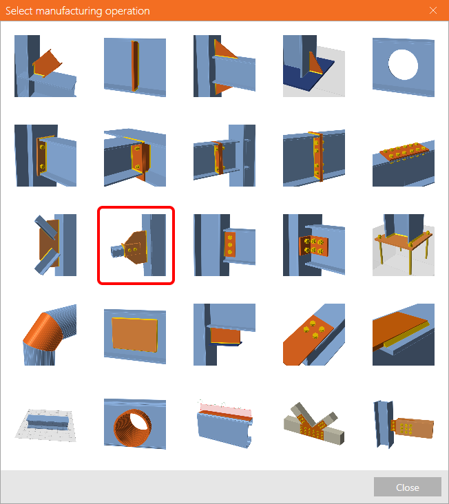
Select the Connecting plate operation from the list of available manufacturing operations.
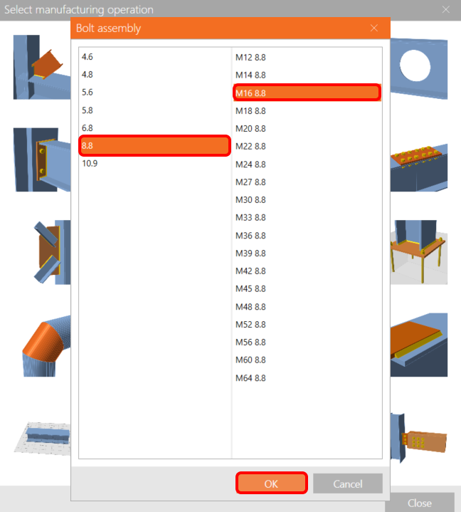
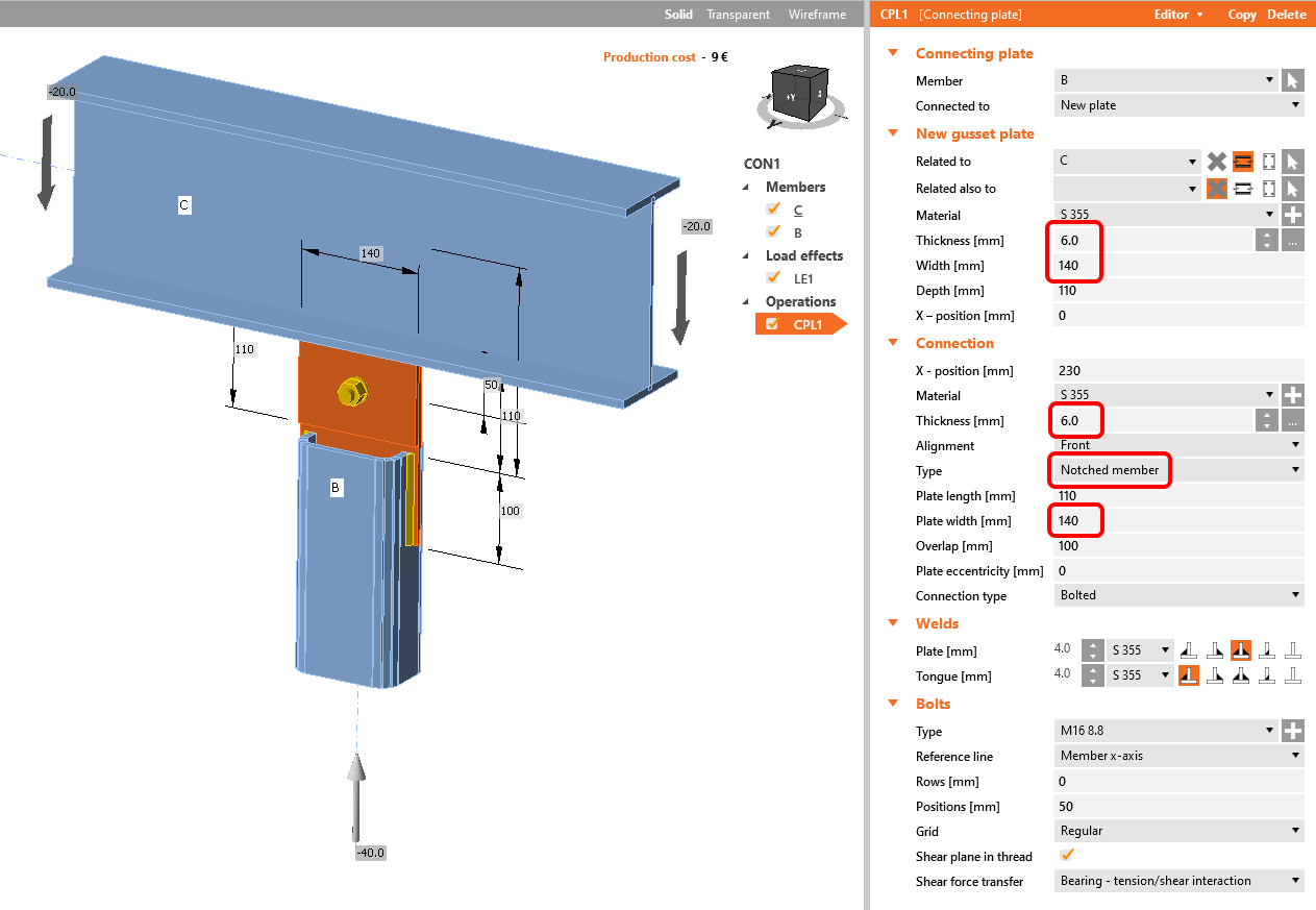
Then select the designed bolt assembly: in this case, choose the M16 8.8 bolts.
Now, define the properties of the connecting plate CPL1. Change the Thickness of the gusset plate and connecting plate to 6 mm, the Width of the gusset plate and connecting plate to 140 mm, and change the Type of the connecting plate to the Notched member.
The model is ready to be analyzed.
5 Calculation and Check
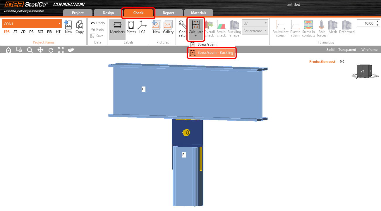
Navigate to the Check tab at the top ribbon and start the calculation of both the EPS (stress/strain) and buckling analysis under the Calculate and Stress/strain - Buckling command.
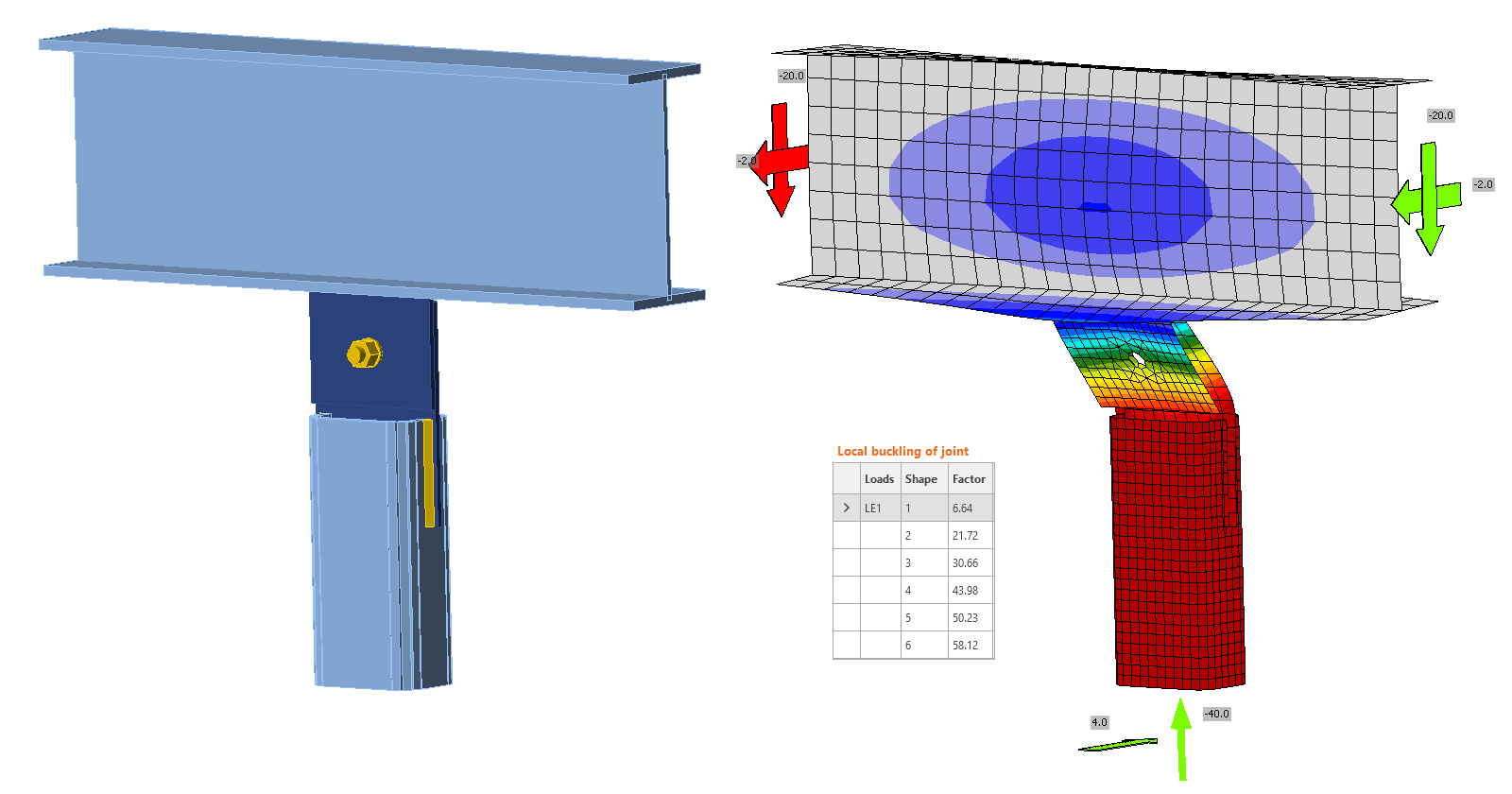
Turn on the Buckling shape, Mesh, and Deformed view. The tab of critical buckling factors is provided in the Buckling tab.
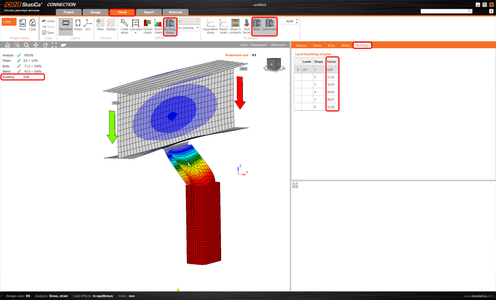
By clicking on each row in the tab of critical buckling factors, you can browse the deformed shapes in the 3D window and analyze them visually.
To understand the results of the analysis, please read the recommended documents, such as the Theoretical Background or Global buckling vs. local buckling. What does it mean? article, or Buckling needs critical thinking! blogpost.
Since this is a case of global buckling and the buckling factor is lower than 15, you should use one of the further measures:
- Simulate the 2nd order effects - add extra shear load perpendicular to the gusset plate as a destabilizing force due to eccentricities with the magnitude of V = N / 10 in the location of the bolt group center; A suggestion for this type of connection can be found in the Gusset plate design in IDEA StatiCa Connection article.
- or strengthen the connection and recalculate the buckling analysis to ensure the critical buckling factor is higher than 15,
- or use a different analysis or approach to ensure the buckling is not dangerous for the designed connection.
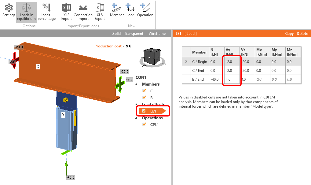
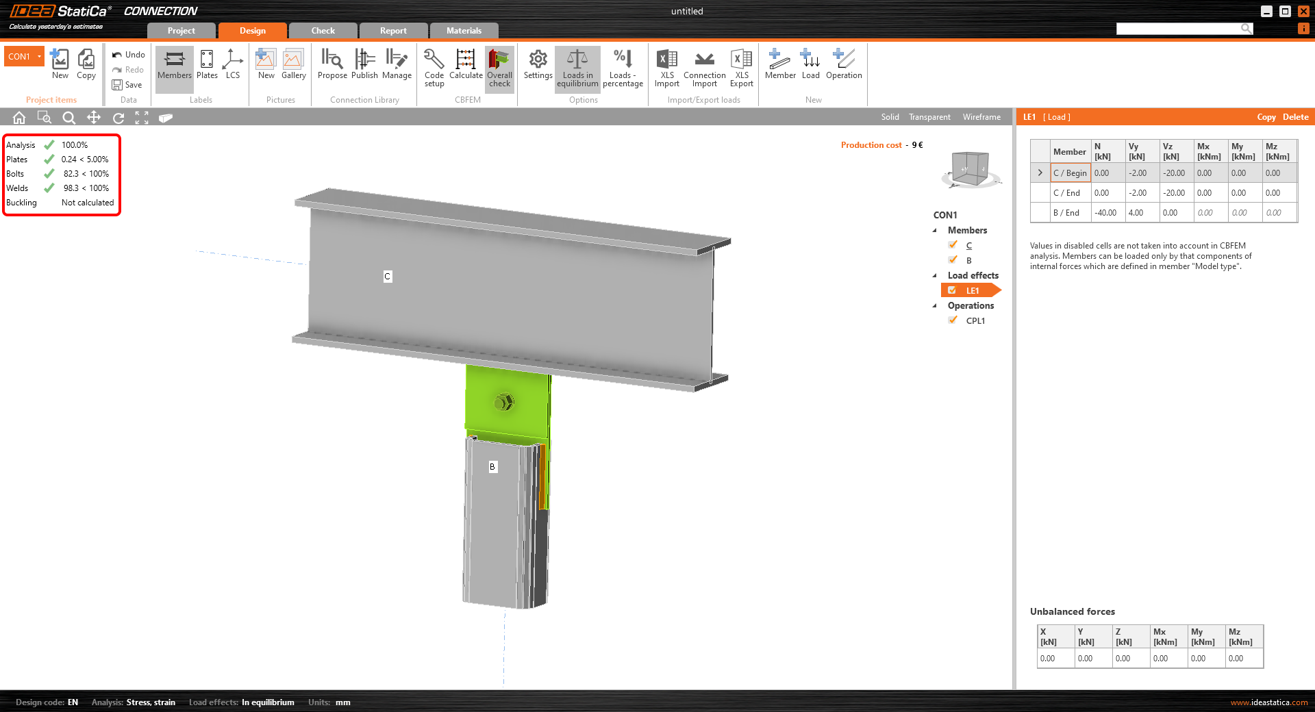
We will use the first measure. Go back to Design, open the load effect LE1, and input 4 kN of shear force Vy to B / End and -2 kN of shear force Vy to C / Begin and C / End.
Recalculate the Stress/strain analysis (no more buckling analysis needed). The overall results show the connection passes all the code checks.
6 Report
As the last step, go to the tab Report. IDEA StatiCa offers a fully customizable report to print out or save in an editable format.
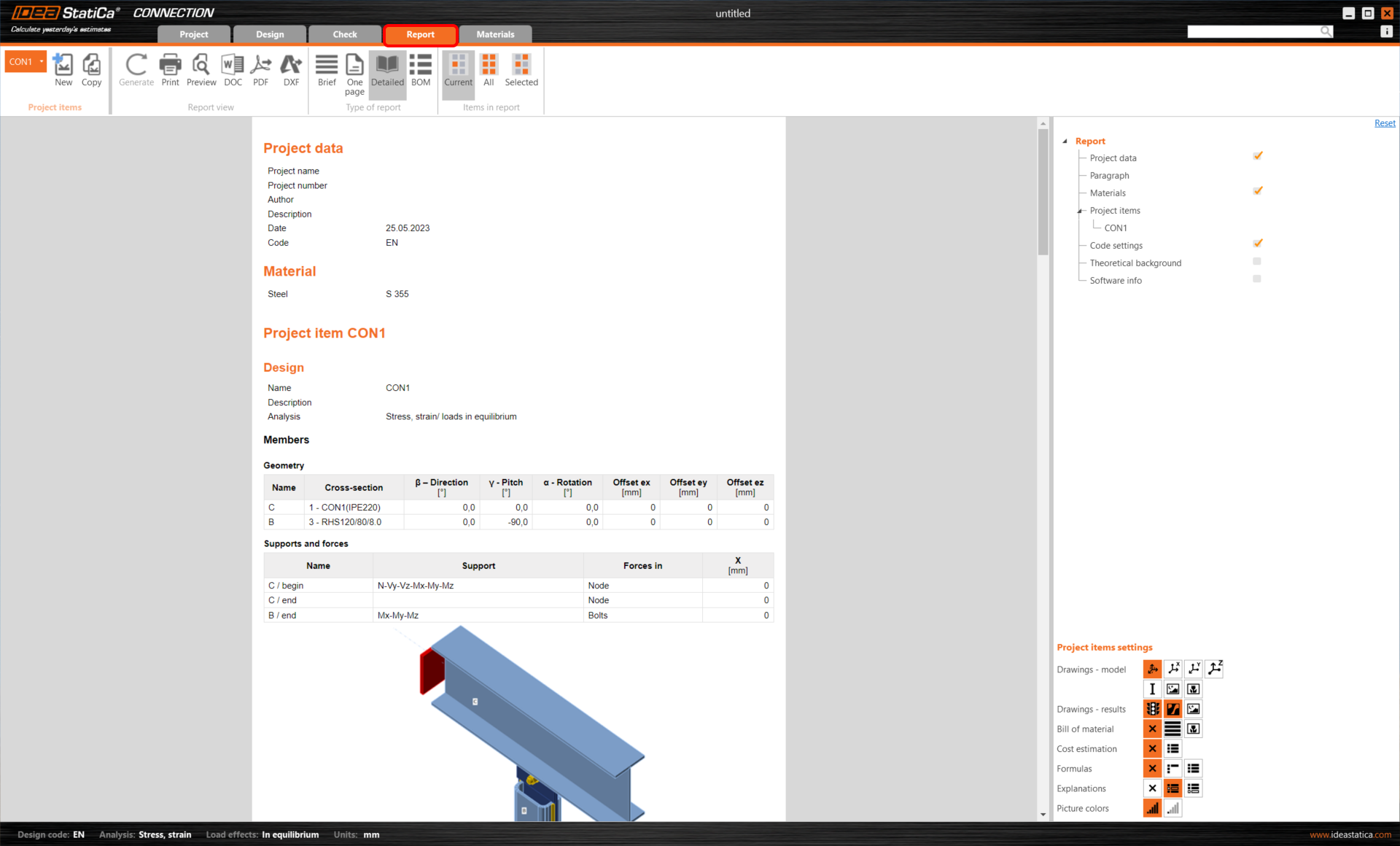
You have designed and code-checked a structural steel joint according to Eurocode (EN).