IDEA StatiCa Checkbot manages your BIM workflows and gives you:
- A clear list of all imported items, including status checked/not checked
- Report for all analyzed and checked items
- 3D visualization of imported members and loads
- A conversion table for materials and cross-sections
- Load combinations management
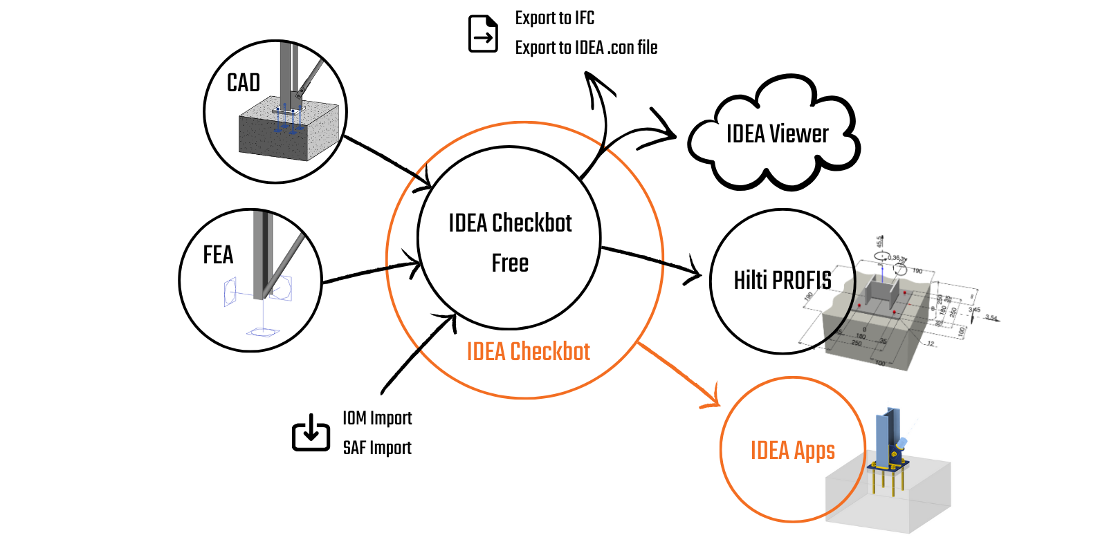
Checkbot is available with both the commercial paid license as well as the free Basic license. The only difference is that the Checkbot Free does not allow you to design and calculate design items in the other apps, such as Connection, Member, or Detail.
The tool's major advantage is that it understands not only the geometry of the original structure but, more importantly, the loading and internal forces resulting from the analysis. Every engineer who transforms internal forces from one analysis to another understands how tricky it can be to keep all the forces in the proper coordinate system. Checkbot can do that for hundreds of load combinations and tens of different tools originating from any supported software.
Importing data into Checkbot
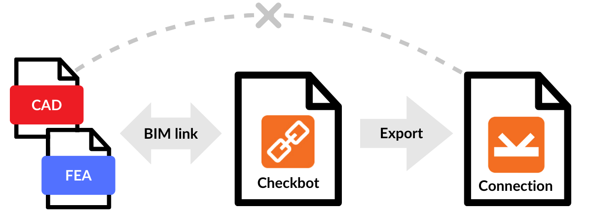
1) BIM Links
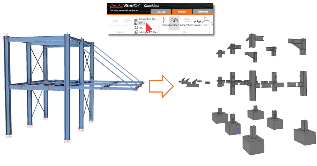
Checkbot works as a stand-alone application, allowing users to open any structural design using BIM links directly in third-party software. The import command bar slightly differs depending on whether the source program is a CAD or FEA (finite element analysis software) type. You can always check supported integrations for steel CAD/FEA software, plus their known limitations, and see a list of supported versions of 3rd party applications.
Following step-by-step tutorials, you will learn how to design and code-check your connections and members using the BIM link between IDEA StatiCa and other software.
- ... and more
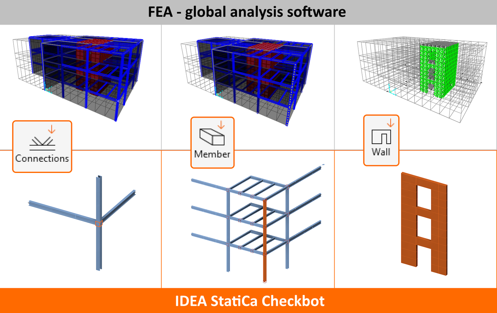
When a Checkbot project is created utilizing the BIM link, the nodes and members need to be chosen to import connections or members.
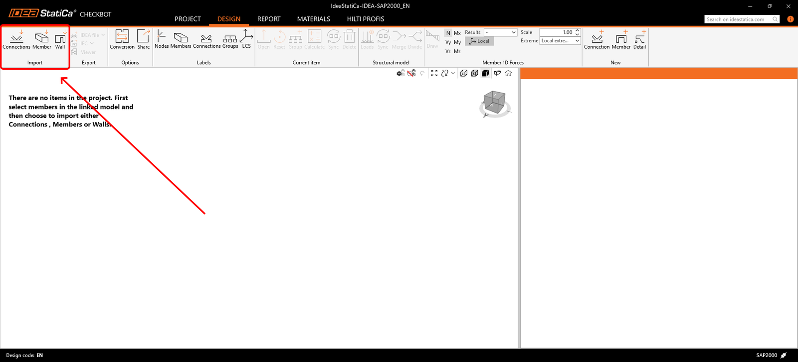
Importing connections/members
- Connection – imports only a selected node and connected members into the Checkbot application.
- Member (analysis software only) – imports selected nodes and beams, which are fundamental for verification in the application IDEA StatiCa Member.
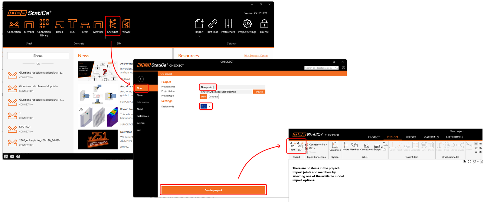
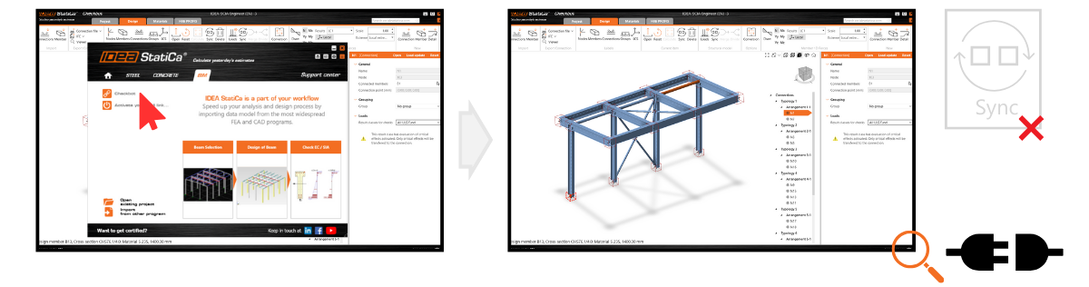
2) SAF/IOM
Another way of importing data from CAD/FEA software is provided using IDEA Open Model (IOM). It also enables the importing and processing of widely used Structural Analysis Format (SAF). An SAF file can be exported from SCIA Engineer, Dlubal software, FEM-Design, SOFiSTiK, Risa 3D, FRILO, Allplan, AxisVM, ConSteel, and many others.
Conversion
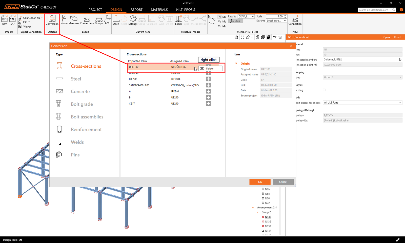
When a cross-section or a material is not recognized automatically during import, a new conversion tab appears to manually assign it from our section/material library. These pairs are then saved for future use within your user account and, therefore, do not need to be defined again.
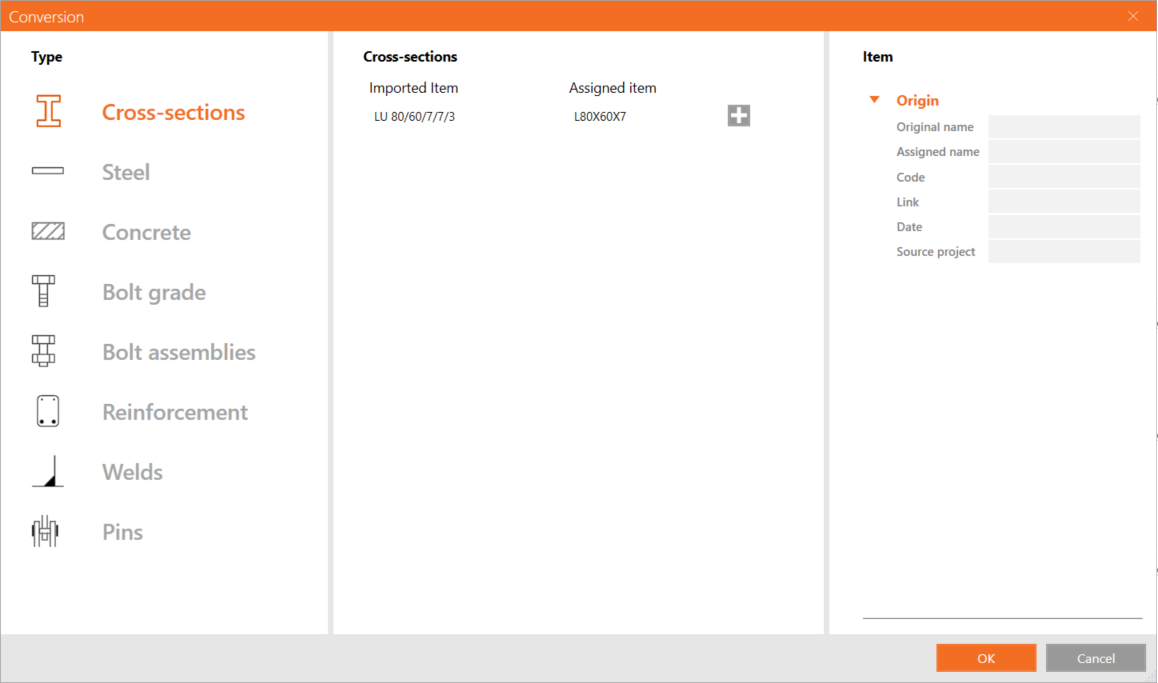
If the cross-section mapping was created incorrectly or needs adjustment, you can add a new mapping by clicking the plus button or remove an existing one by right-clicking and selecting Delete.
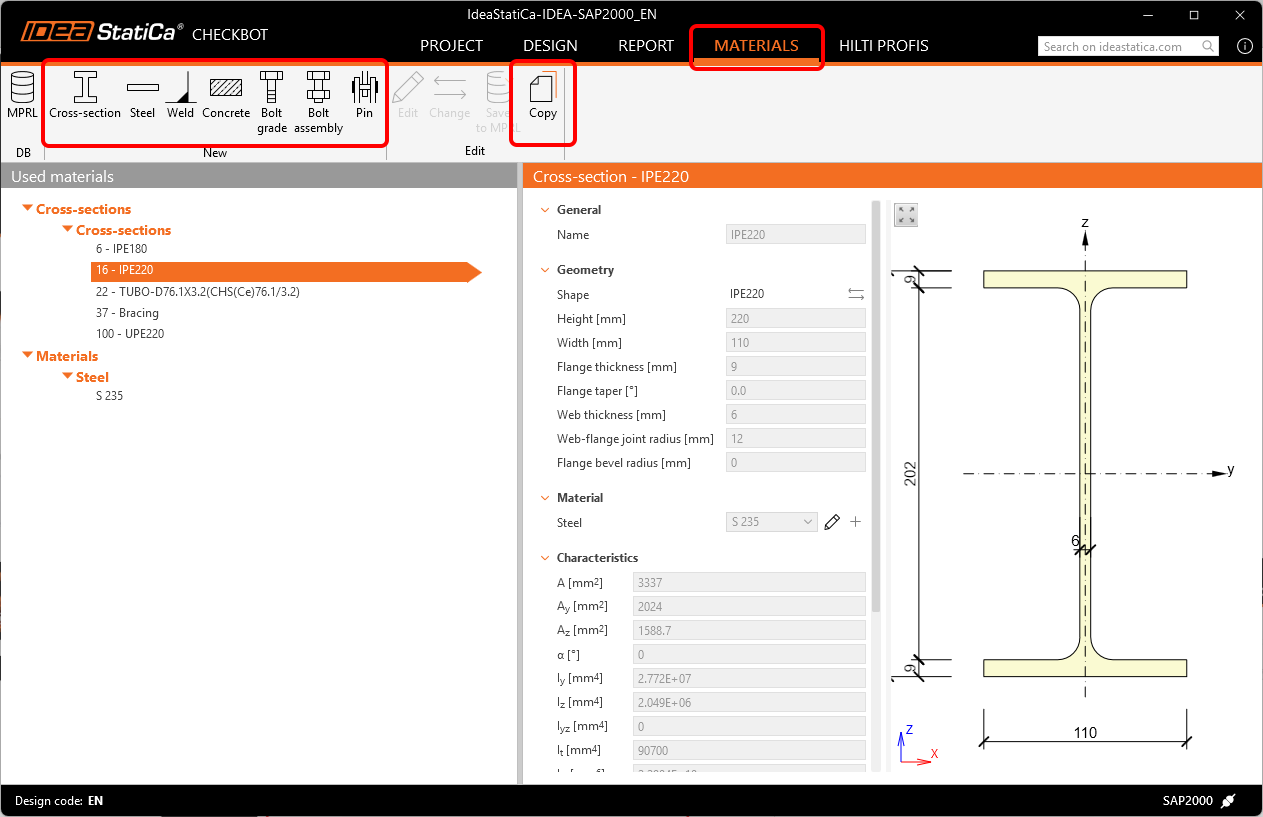
All materials used in Checkbot are listed in the Materials tab. All imported materials and cross-sections are disabled from making any changes. To modify their parameters, a copy needs to be created or completely new material added.
The conversion tab is saved for each design code in a separate .XML file in the following folder:
C:\Users\YOURUSERNAME\AppData\Local\IdeaStatiCa
Here, the conversion files can be modified manually, deleted completely, backed up, or shared with other users.
Numbering and local coordinate system
The numbering and local coordinate system of members in Checkbot and in third-party software might be different. Since Checkbot is based on a load-mapping algorithm, there is no need to be worried. Checkbot recognizes and identifies the corresponding members and reliably assigns the correct load effects to them.
How to work with Checkbot
Load configuration
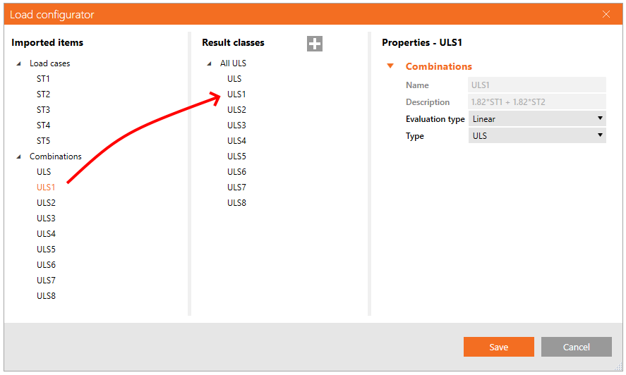
The Load configurator displays the imported load cases and load combinations. The first column lists all the Load cases and Combinations imported from the linked FEA model. The second column shows the load cases and load combinations in the result classes used for calculations in the Checkbot project. By default, one result class with all load combinations is used. Furthermore, the third column displays detailed descriptions of the currently selected entity.
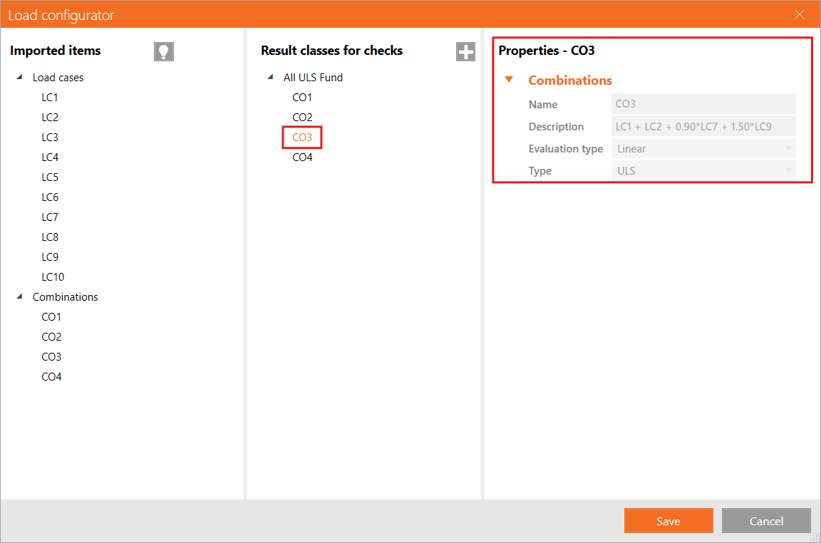
Imported load effects can be re-assigned manually to Result classes. Result classes are meant to sort load effects to specific groups, which can simplify and speed up the design process. Result classes can be added using the "+" icon and removed with a right-click of the mouse. Load cases and combinations can be assigned under a result class by dragging them from the first column under the appropriate result class in the second column.
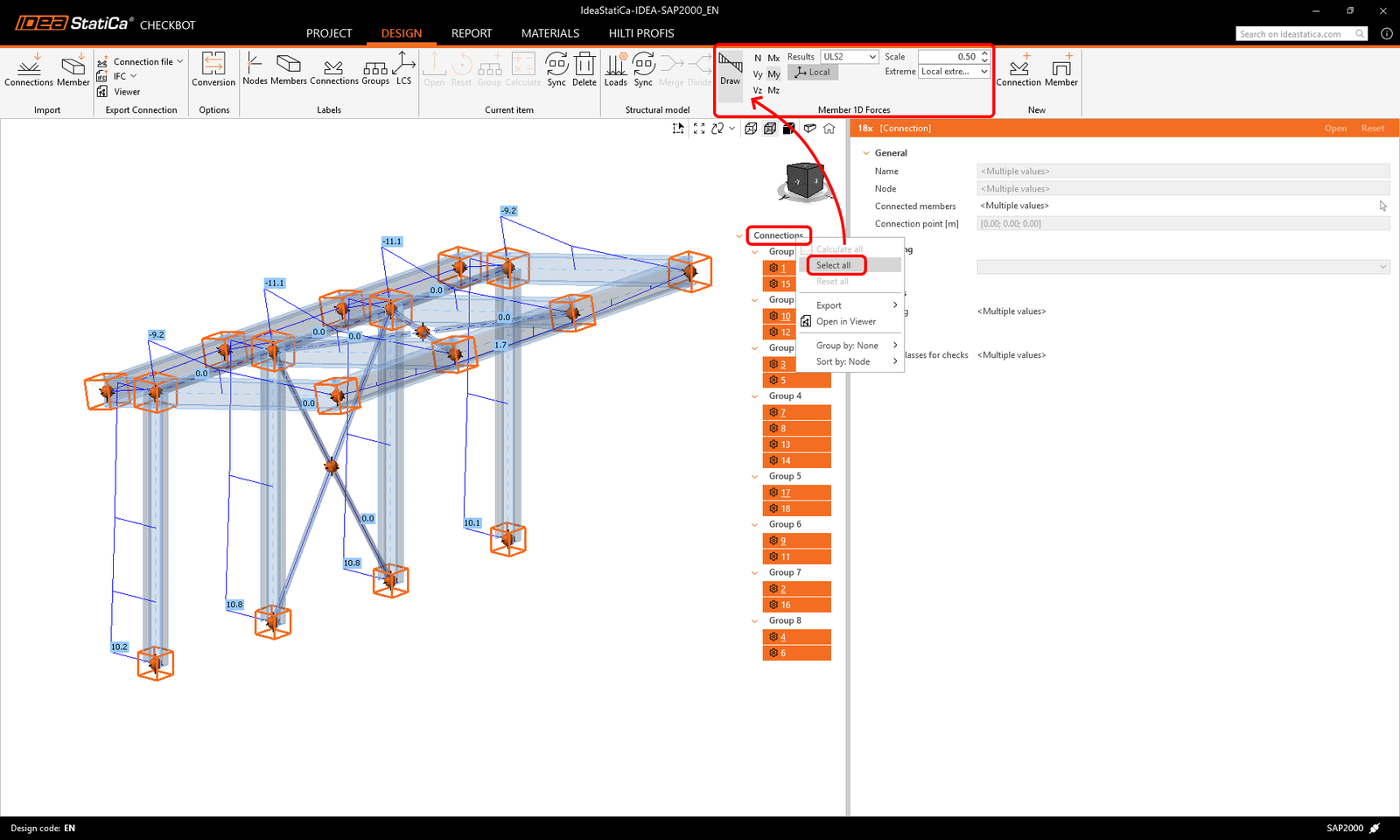
Checkbot also visualizes the internal forces of imported combinations. Right-click connections/members or choose all of them and select the load combinations and internal forces to be displayed.
Please be aware that not all load combinations are compatible with Checkbot (e.g., dynamic combinations, nonlinear combinations), depending on the FEA software. Some combinations might be imported as load cases, which, however, do not affect the results. Always check the known limitations of each BIM link:
The load configurator allows you to activate the evaluation of critical effects* in complex structures. This feature selects load cases and combinations with maximum and minimum load effects, filtering out the rest. It takes into account the stresses in the top and bottom fibers of the cross-section to speed up the code-check calculations.
* The Evaluate critical effects function was removed and replaced by the Calculate load extremes function since version 25.1.2.
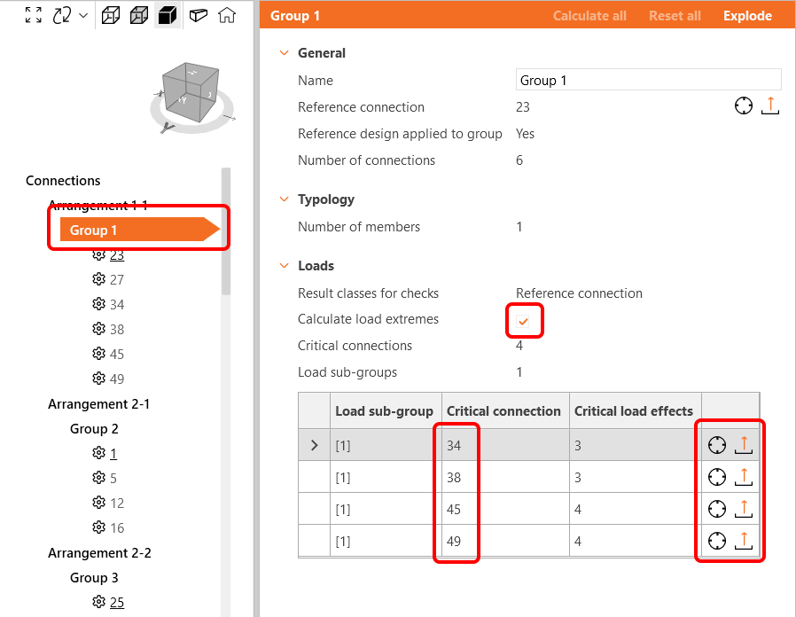
Calculate load extremes function
In projects with many nodes and load combinations, similar connections with very similar load effects are analyzed repeatedly. To speed up a calculation process, you can use the Calculate load extremes button to define only the load extremes containing the critical load effects. This will reduce the number of examined load effects as well as the time of calculation. Read more in this article.
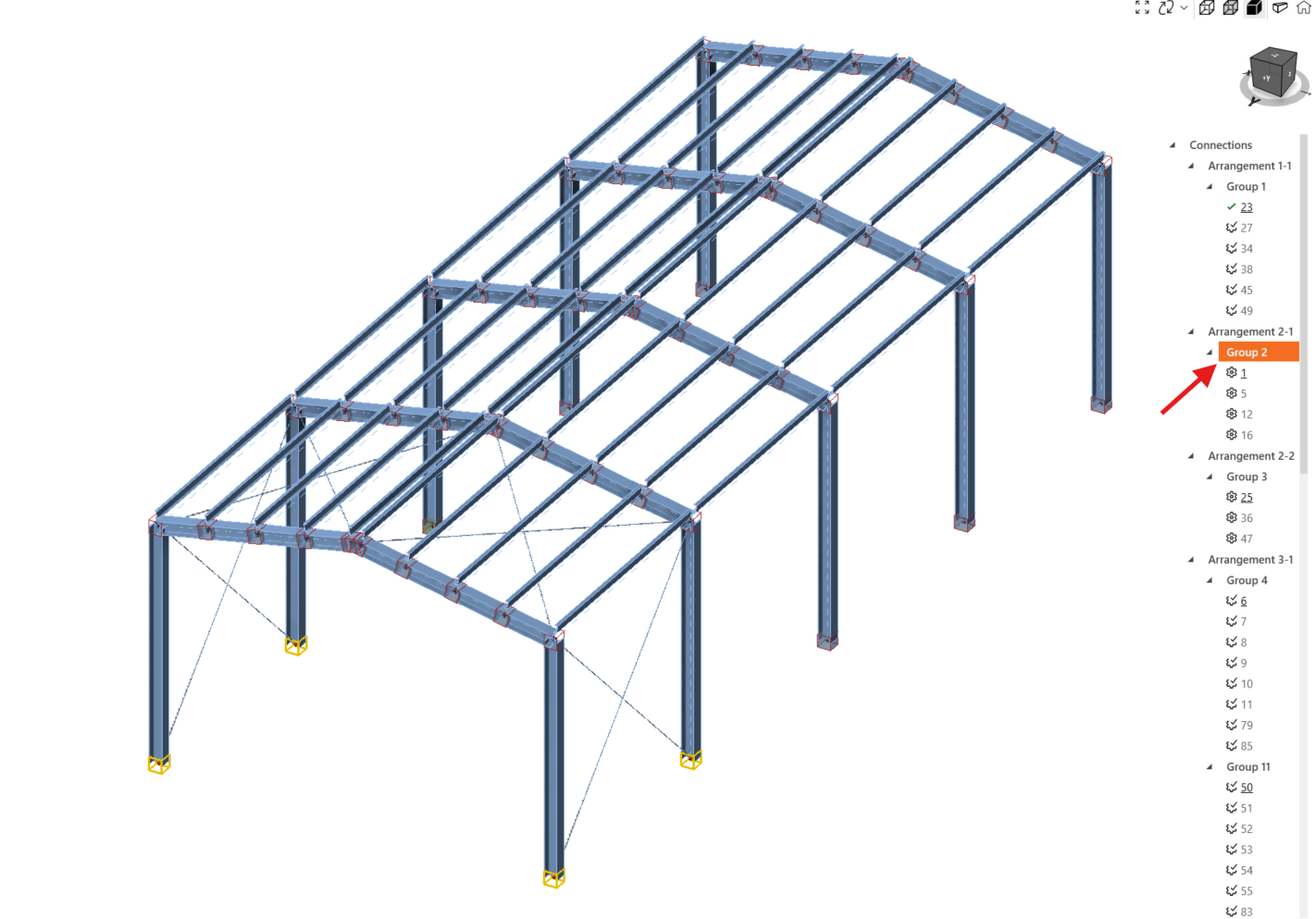
Dynamic grouping
The grouping functionality automatically creates groups based on typology and/or cross-sections. The groups are then ordered from least complex to most complex based on the number of connected members. Every group is represented by the reference connection (underlined in the tree), which works as the parent connection that drives the design for the whole group. All other connections are treated as child connections.
- Reference connection (the one underlined) - here you create the design and settings for the connection
- Child connections (all the rest in the group) - editing is disabled, design and settings taken from the Reference connection
Any operations added to the reference connection will automatically be duplicated to the child connections to avoid repetitive work, including project settings, position of the load, and model type. Adjustment of the child connection is disabled. If adjustments are needed, right-click the connection and select Remove from group. Once a connection is ungrouped, all operations copied from the reference connection will also be deleted.
The reference conection is chosen during the import as the first selected node for given group in the global structural model, and NOT based on the highest loads within the group. Child connections can have higher loads than the Reference connection.
To change the Reference connection, you have to explode the group, create a new group with the single connection wanted as the Reference one and then assign the rest of connections to this group.
User-defined groups
Furthermore, users can create their own groups, allowing further customization and enabling organization based on specific project needs.
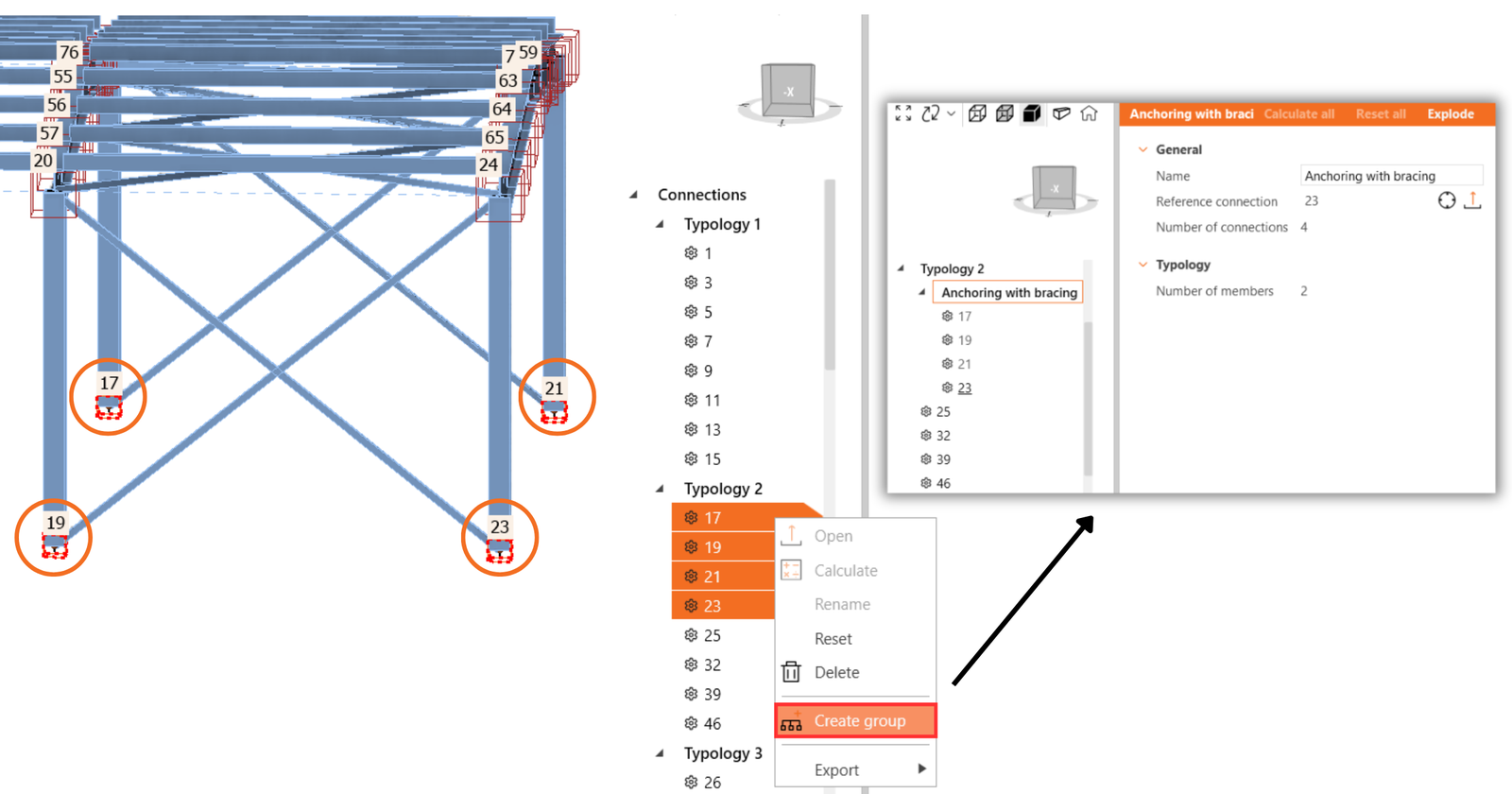
To define a specific connection as a reference, start by creating a group that includes only the desired reference connection. Once the group with the one reference connection is created, add the other connections to the group. You can select multiple connections and change their group with one click.
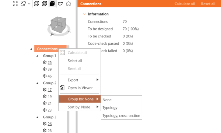
Grouping in the tree
None arranges connections according to groups only.
Typology grouping considers the number of members and their relative positions (beam-to-beam, beam-to-column). It does not consider the rotation of members. The dynamic groups are considered too.
Typology, cross-section (Arrangement) grouping differentiates typology groups according to designed cross-section types. For example, a HEB 200 and a HEB 220 are under one cross-section type. Grouping according to typology and arrangement is set by default. The dynamic groups are considered too.
Released in IDEA StatiCa version 25.0.
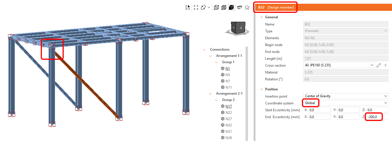
Alignment of members by cross-section
Single-select, multi-select, or area-select allow users to effectively input the local and global eccentricities and align members to match their surfaces across the entire structural model imported to Checkbot.
This is a necessary step between the global model imported from FEA software, where the geometry is simplified, and the CAD-based design model in IDEA StatiCa Connection, where the geometry matches the real design.
To perform the area selection, click the Select multiple members with area selection icon located in the 3D scene and select the members. Drag from left to right – only members inside the selection area are included, and drag from right to left – also members intersecting the selection area are included. Turn off the area selection by clicking the icon again or pressing the ESC key.
You can input eccentricities for single or multiple members at once. Select the Local or Global coordinate system and input the positive or negative eccentricity for the member's start point and end point in X, Y, or Z direction.
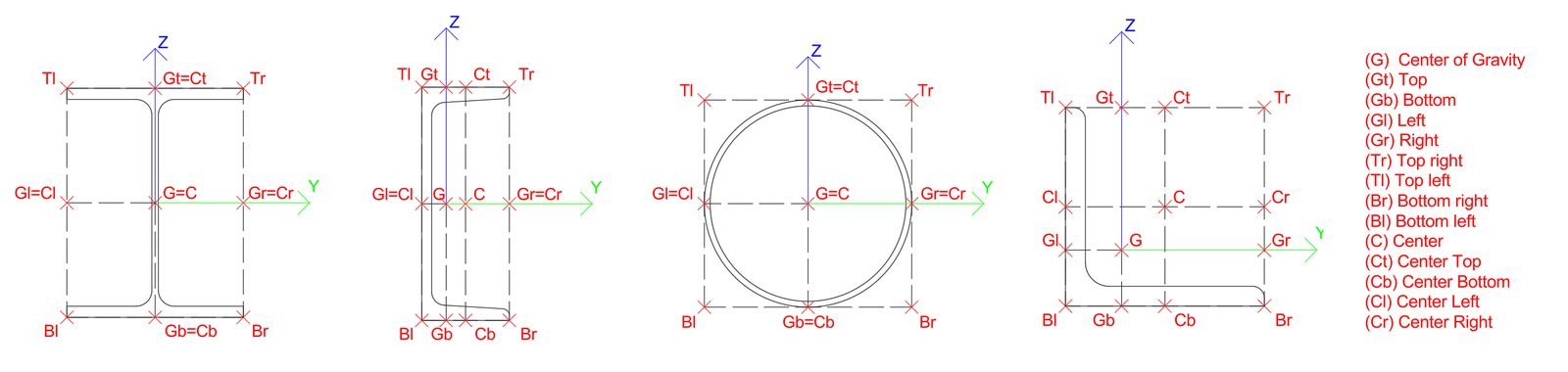
To align members, select the members that should be aligned together and choose the Insertion point option, to align, e.g., to the top surface, center of gravity, left surface, etc.
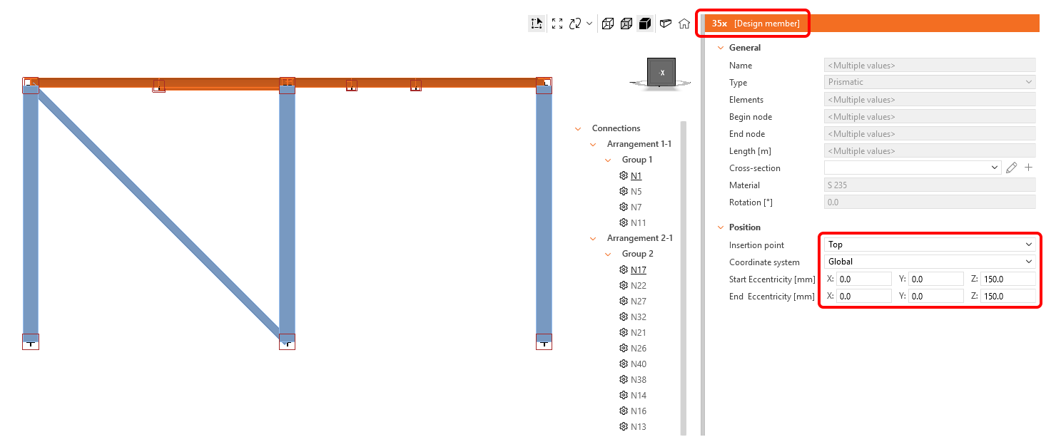
The Insertion point allows the selection of multiple points over the cross-section of the member. The FEA programs usually use shortcuts for the insertion points, which are translated in the Checkbot list as follows:
| G | Centre of Gravity | Tr | Top right | C | Centre |
| Gt | Top | Tl | Top left | Ct | Centre Top |
| Gb | Bottom | Br | Bottom right | Cb | Centre Bottom |
| Gl | Left | Bl | Bottom left | Cl | Centre Left |
| Gr | Right | Cr | Centre Right |
Note: Internal forces are not updated with the alignment or added eccentricity. This can result in the generation of additional bending moments in the touched members as a consequence of changing the geometry disposition. To prevent this, the alignment and eccentricities should be properly set in the FEA global model before import to Checkbot.
This feature might be limited for FEA software where the BIM link with IDEA StatiCa is developed by the FEA producer or a third party – check the supported integrations list.
Released in IDEA StatiCa version 25.1.
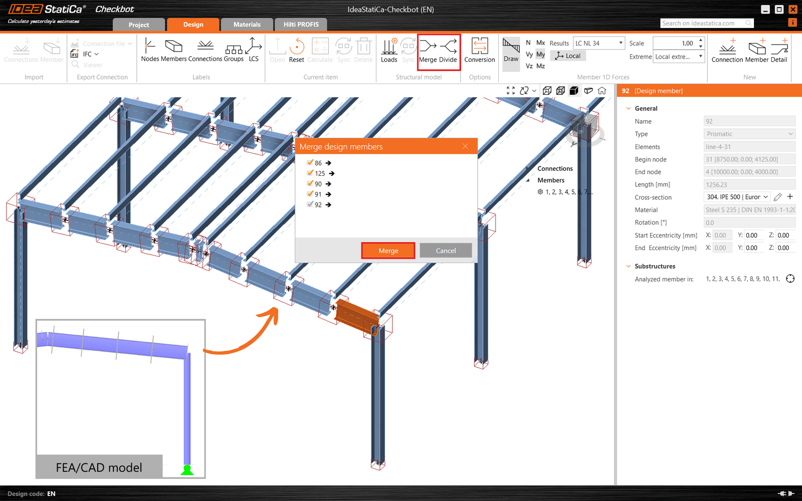
Merge members
In some cases, in the analysis software model, a member might be split into multiple members, but in reality, it is one continuous member. For these cases, the Merge functionality can correct it. Right-click one of the split members you want to merge and tick the other members that you want to connect. Please be aware that only members aligned along the same X vector are mergeable.
Additionally, if you need to undo a merge, the Divide button allows you to separate any members that have already been merged back into their original state.
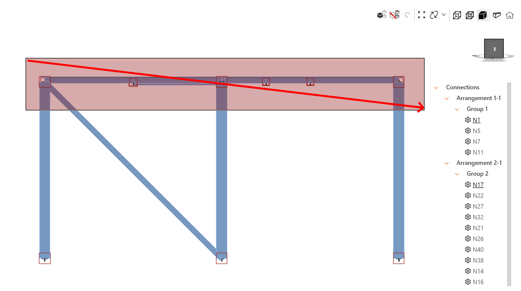
Merge connections
Connection configurations with multiple structural nodes close to each other that should be analyzed in one connection model (one joint) might be imported as two separate connections, typically appearing for eccentric diagonals.
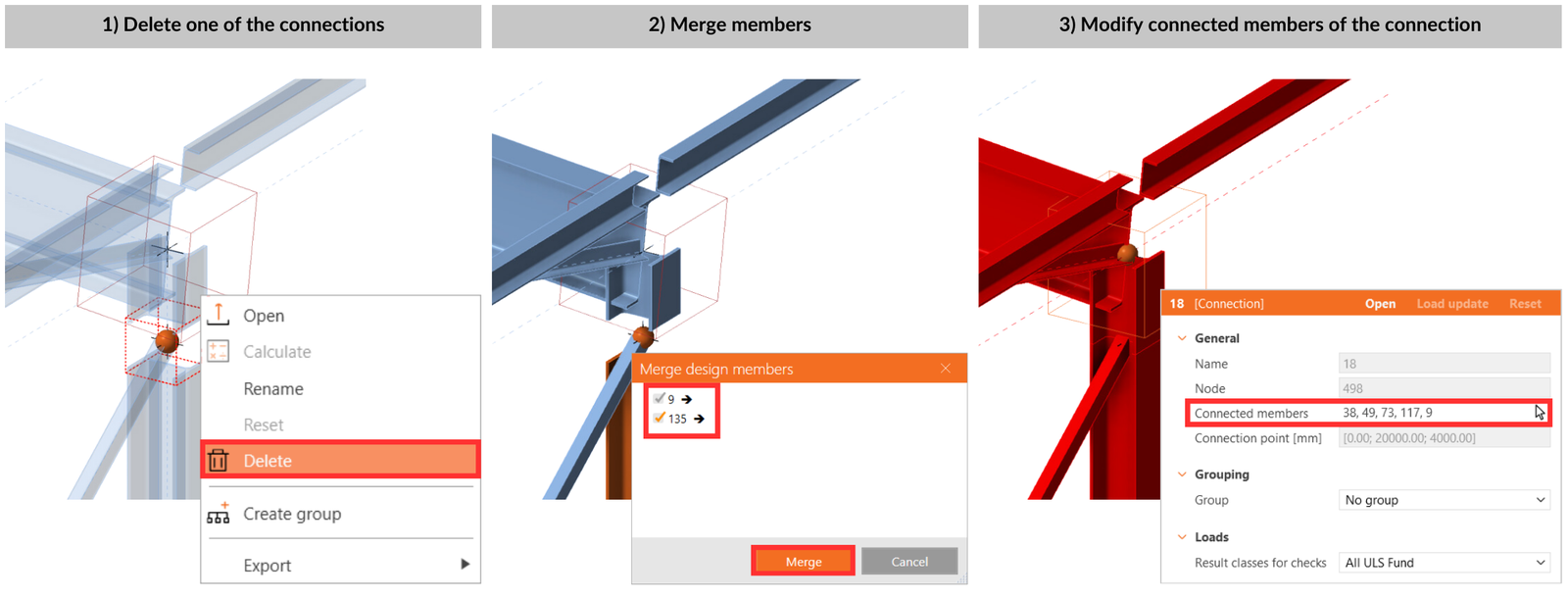
Via right-click on the box in the 3D scene or by selecting them in the tree list, delete all connection items (structural nodes) represented by empty boxes, except one. Add all members belonging to the one connection using the arrow icon next to the Connection members parameter (selected highlighted in red).
Connection manager
For an organized overview of the project, Checkbot offers a summarized project status displaying the total number of connections, how many still need to be designed, and the number that has been checked. It also shows how many connections have passed or failed the code check, giving users a comprehensive view of the project's progress at a glance.
To access the overview, click Connections in the tree and all data will be displayed.
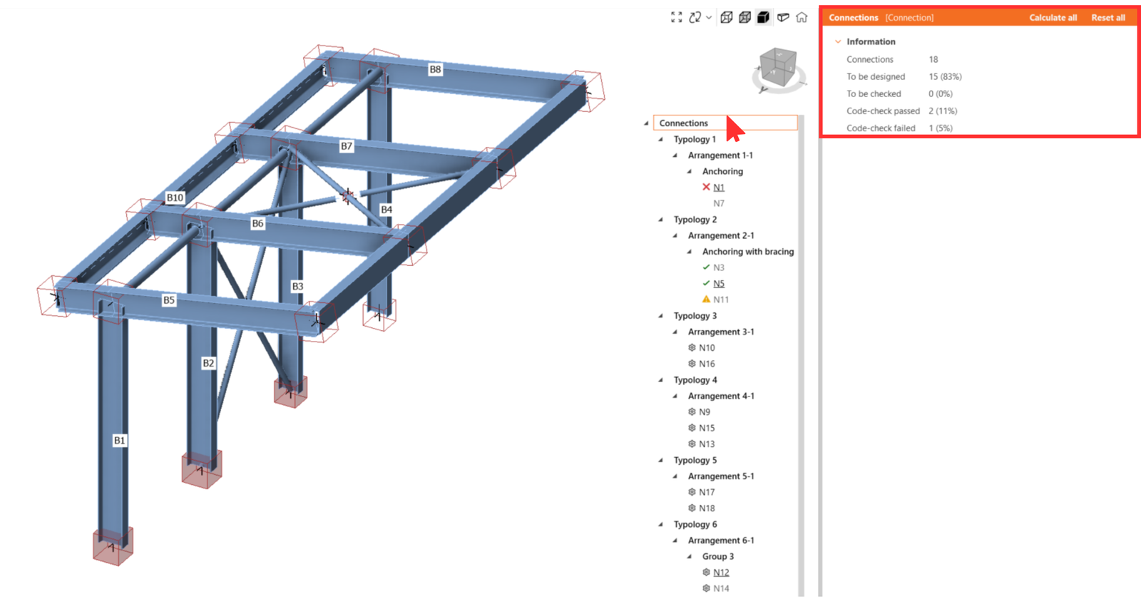
Furthermore, every connection is marked by the following icons to provide a quick overview.
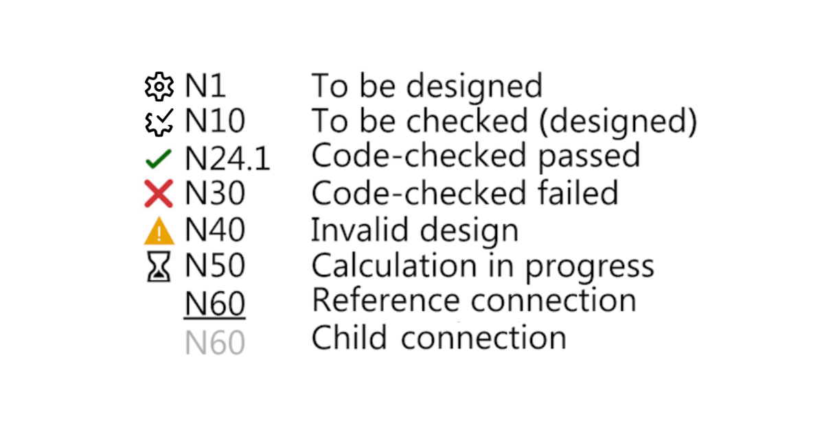
- Cogwheel – not designed
- Cogwheel with tick – ready for calculations
- Green tick – calculated and code-checks passed
- Red cross – calculated but code-checks failed
- Invalid design – with a sync or update of the structural model, the child connection no longer meets the reference connection's parameter. Design update or potential regrouping needed.
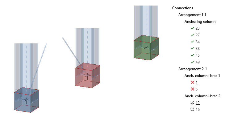
Colors of boxes in the 3D-Scene
A selected connection item is highlighted with the orange wire frame in the 3D scene. All connections related to the same group of the selected connection are highlighted with the yellow wire frame.
The status of the connection is visible not only in the tree list, as mentioned above, but also directly in the 3D scene, and it is represented by the following colors:
- none - to be designed
- blue - ready to be calculated
- green - calculated and code-checks passed
- red - calculated but code-checks failed
Released in IDEA StatiCa version 25.0.
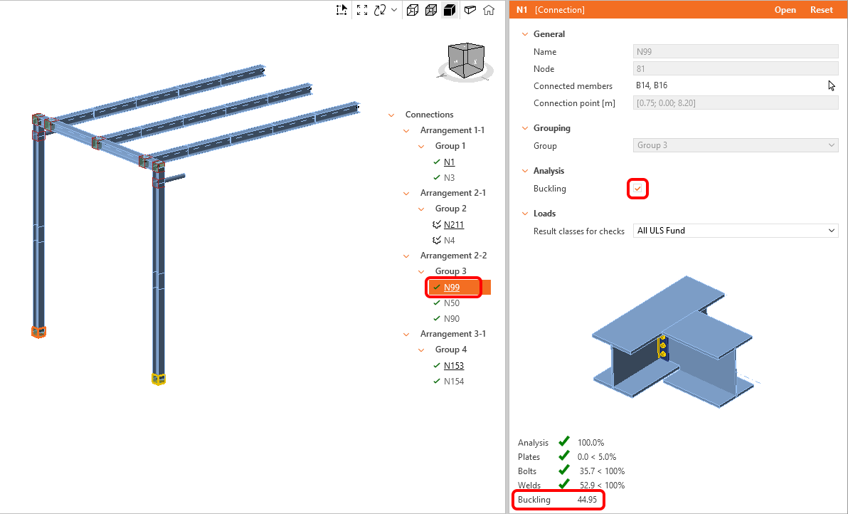
Calculate buckling analysis for all connections
Buckling analysis can be calculated in bulk for selected connection groups. By default, the buckling analysis is turned off. To turn the buckling analysis on, select the Reference connection, and check the Buckling combobox.
The lowest buckling factor is displayed in the overall results tab in the Checkbot window and also added to the report.
Released in IDEA StatiCa version 25.1.
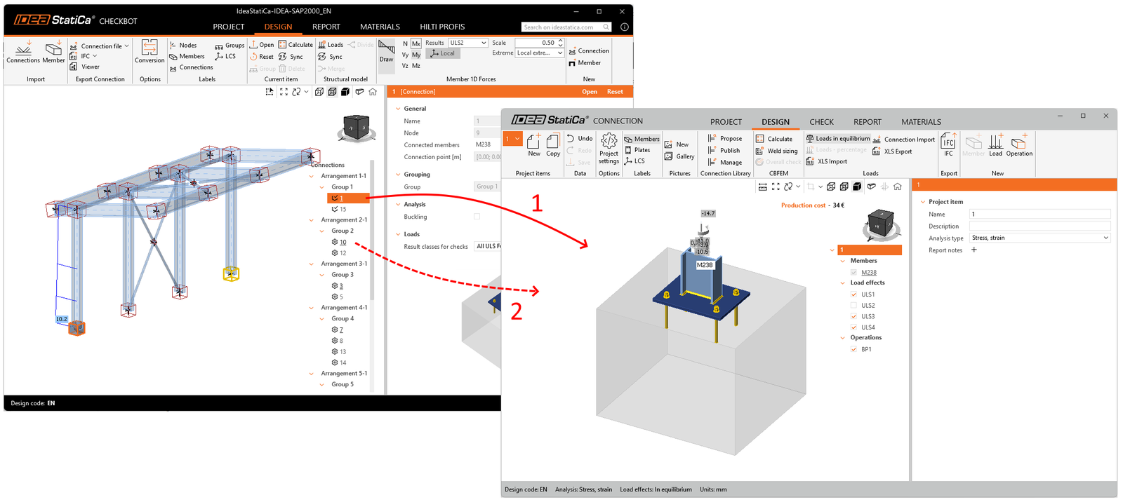
Working with Checkbot and Connection window simultaneously
Especially when working on computers with two displays, once the Connection app window is opened from Checkbot, do not close it. Just go back to the Checkbot app and open another connection item. The Connection window will reload quickly. This is much faster than closing and opening the Connection window for each connection item reviewed.
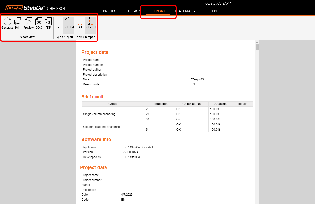
Bulk Report
The report can be generated for all connections in the project at once or for selected connections only. The level of detail, number of chapters included, and additional handwritten notes with pictures can be adjusted in the Report tab. How to adjust the report accordingly is explained in this article.
Export to Connection
When Checkbot is linked to third-party software via a BIM link, it does not allow you to edit the geometry and properties of members, editing is disabled. If such changes are necessary, you can export any connection item from Checkbot to a single IDEA StatiCa Connection file and edit every part of the model. You can export one connection or select multiple connections at once.
The exported single Connection file is independent of the Checkbot project. Therefore, no further synchronization with the FEA structural model or its management in Checkbot is possible.
Released in IDEA StatiCa version 25.0.
Export to IFC
The Industry Foundation Classes (IFC) format is an open data, vendor-neutral format that enables the sharing of data. Checkbot allows you to export all selected connections to one IFC model or export connections to individual IFC files to a specific folder.
The export contains the global coordinates of the Connection Point – the real location of a connection in a project.
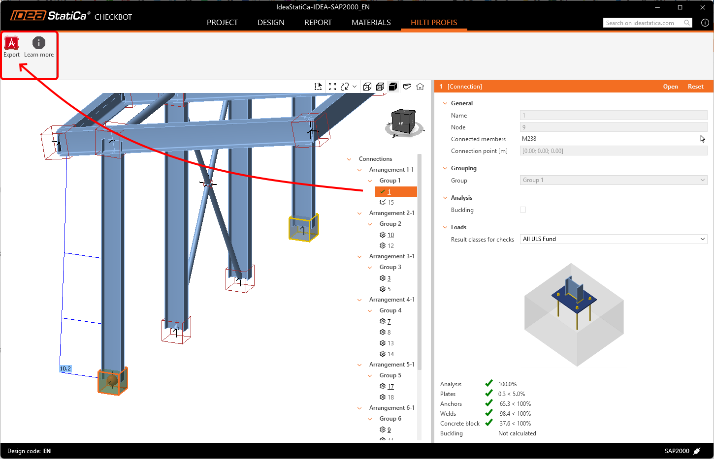
Export to Hilti PROFIS Engineering
Hilti PROFIS Engineering Suite is a user-friendly, cloud-based software for designing and analyzing anchors. By selecting a node with one anchored member, users can export the data directly to Hilti PE using the Export button, ensuring the accurate transfer of relevant structural data for further analysis.
This entire workflow is available even with a IDEA StatiCa Basic license, meaning that it is available for free. How to use the plugin is described step-by-step in the following article, which is also accessible from the Learn more button in Checkbot.
Synchronization
After importing all necessary items, the Sync button lets you easily detect and apply changes from the source project to the IDEA StatiCa model. These changes may include updates to thickness, cross-sections, or modifications to the properties of welds and bolts. However, it’s important to note that updates cannot include new or deleted components such as plates, members, repositioned elements, or load combinations. In such cases, you must delete the current Checkbot project (the folder) and import it again.
Please keep in mind that synchronization in IDEA StatiCa works one way, from the source program to IDEA StatiCa, not the reverse.
- FEA solution – sync does not affect design operations (cut, end plate, ...)
- CAD solution – sync does not affect load effects (except for Revit, which can hold the analytical model with results)
If any changes are made in the third-party software model later, you must re-open the Checkbot project and press the Sync button to ensure all updates from the third-party software model are reflected in Checkbot. The sync button is enabled only if the Checkbot file is open through the third-party application.
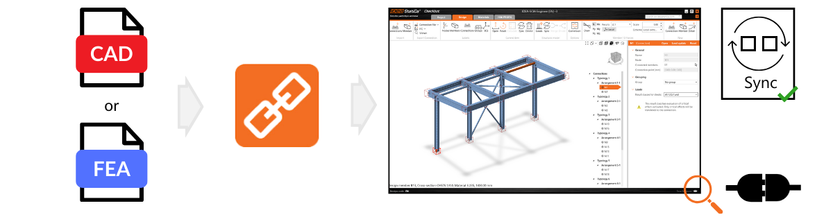
Remember, the Sync button is only active if Checkbot is opened through a BIM link from third-party software.
Be aware that any modifications made directly in IDEA StatiCa (e.g., to cross-sections, eccentricities, load combinations, or operations) will be overwritten during synchronization with the source project. The same rule applies if the eccentricities are modified in IDEA StatiCa.
For example, if you adjust a connection design in IDEA StatiCa Connection that was initially imported from Tekla Structures and then synchronize, your changes in IDEA StatiCa will be replaced by the latest design data from Tekla Structures.
Released in IDEA StatiCa version 25.0, updated in IDEA StatiCa version 25.1.