
Structural design of footing with diagonal (EN)
1 New project
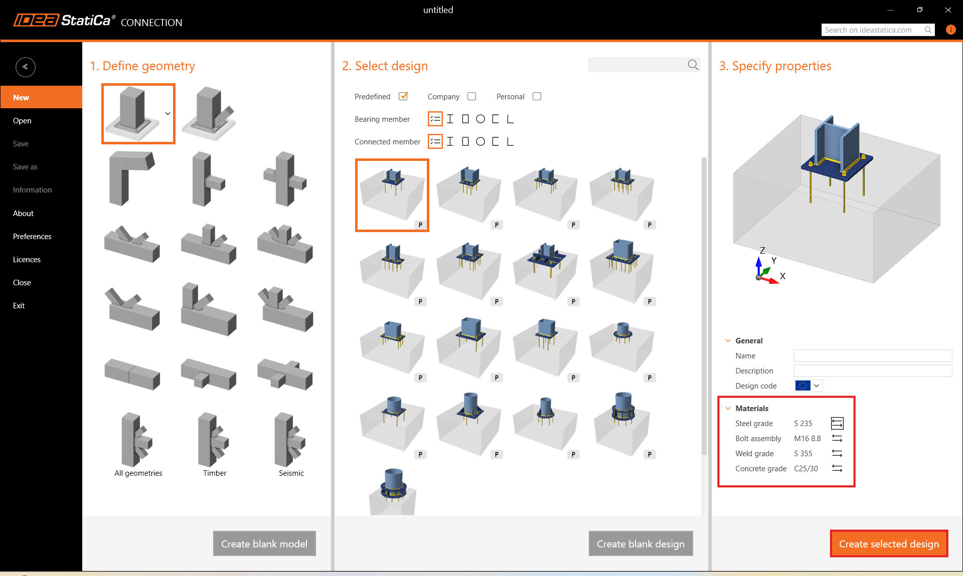
Let’s launch IDEA StatiCa and select application Connection. Create a new project by selecting a starting parametric template closest to the desired design, filling in the name, and choosing the design code and default material properties – S 235.
2 Geometry
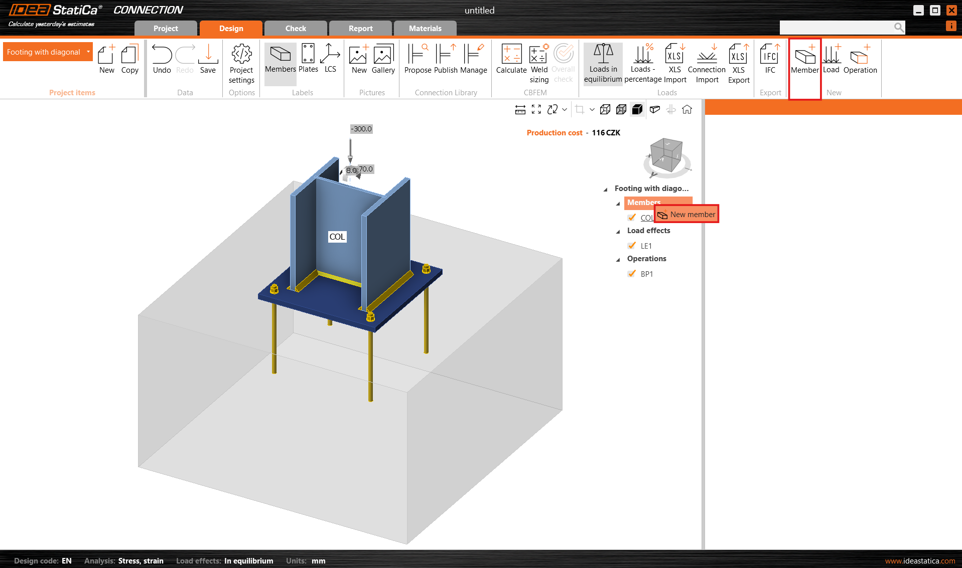
A column and a base plate with anchors were automatically added.
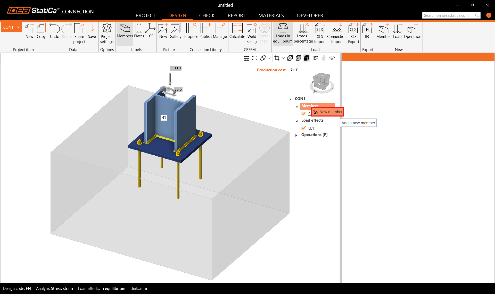
Add a new member. You can either use the Member button in the top ribbon or right-click on the Members in the navigator tree.
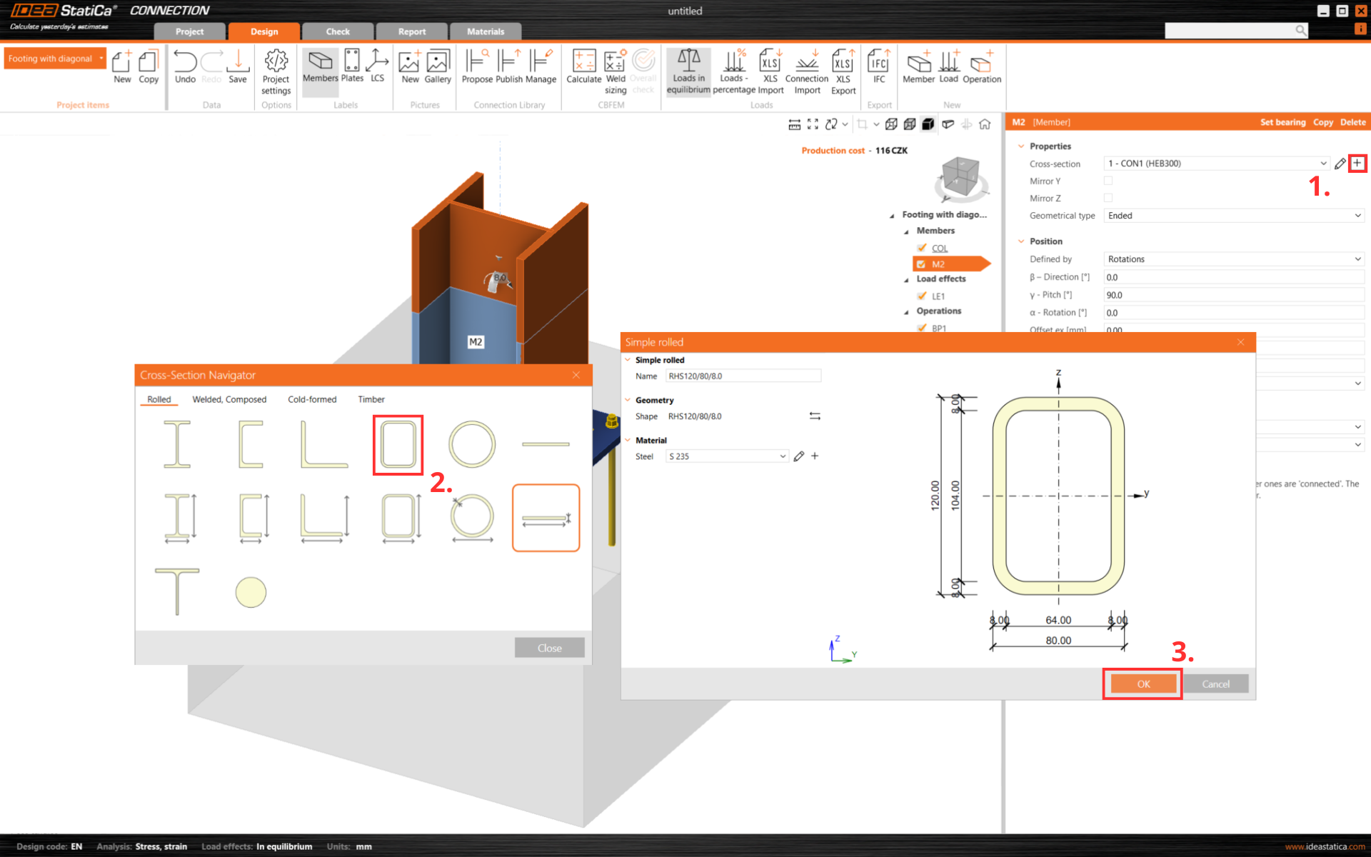
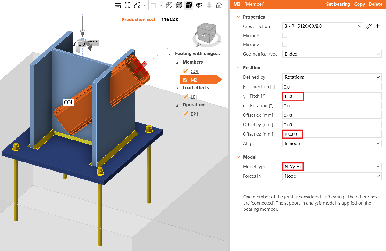
And change its cross-section to RHS120/80/8.0.
Change the member pitch and the value of the offset ez. Set the model type to N-Vy-Vz since this member is able to transfer only axial forces, otherwise the mechanism/singularity could occur or the analysis could fail.
For more info about the model type, see here.
Add another member and change its cross-section.
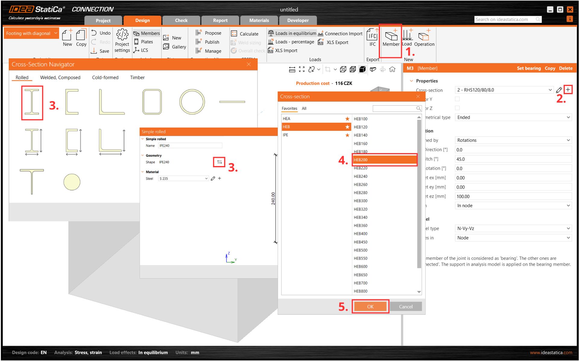
Then modify its properties.
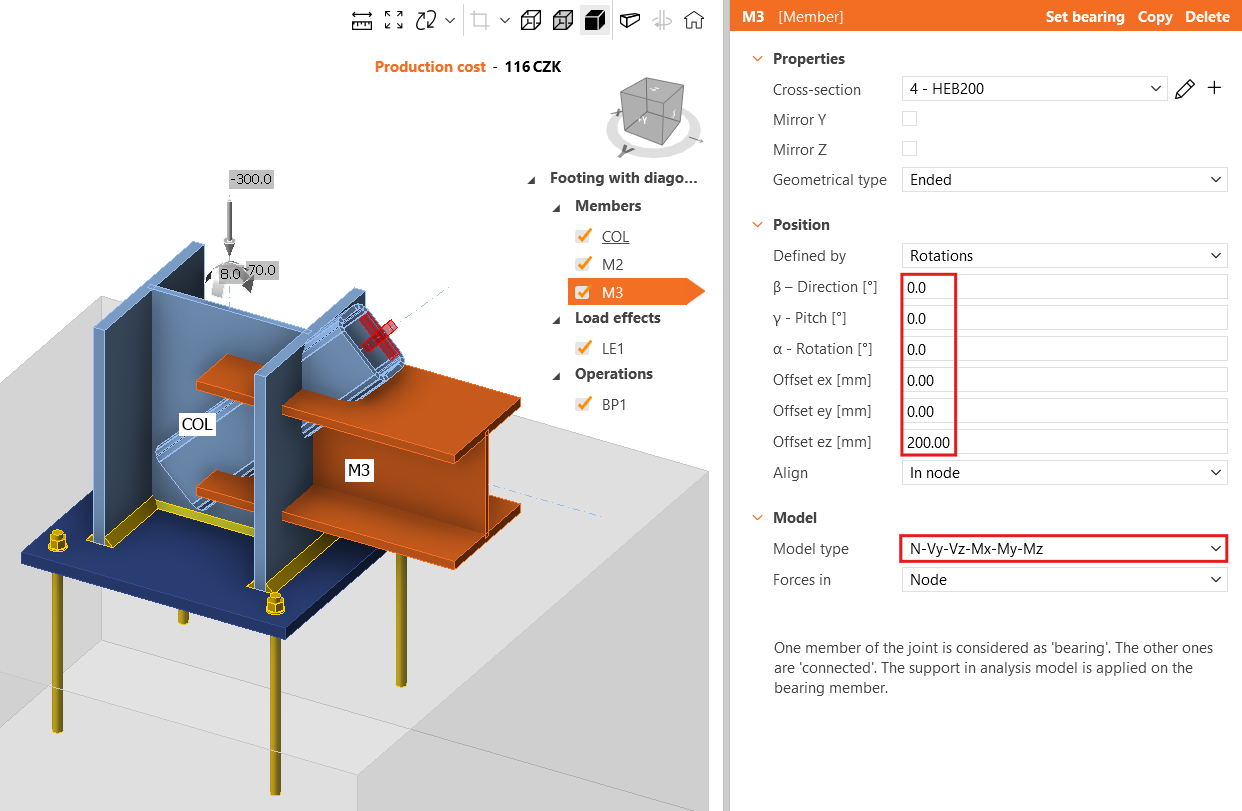
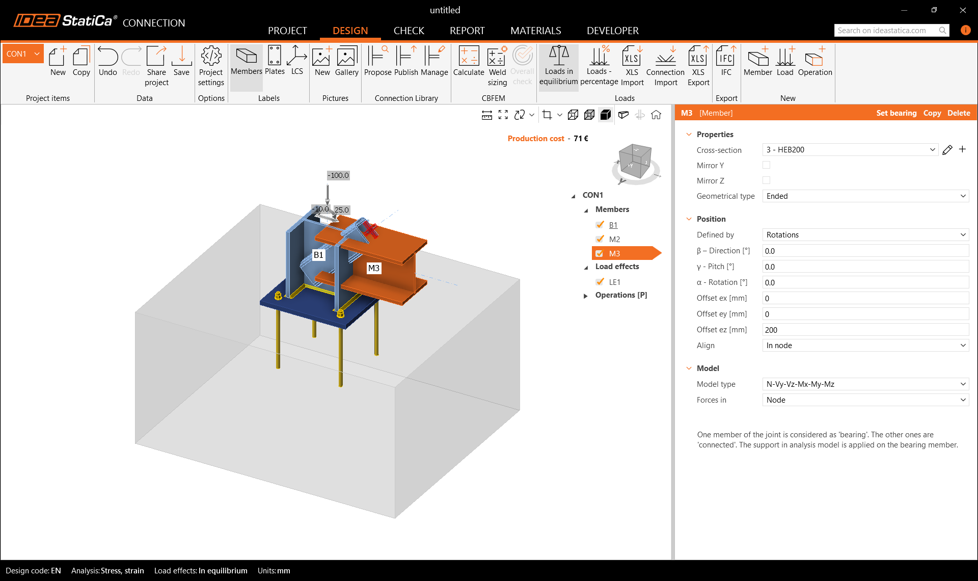
Check the geometry of the whole model.
3 Load effects
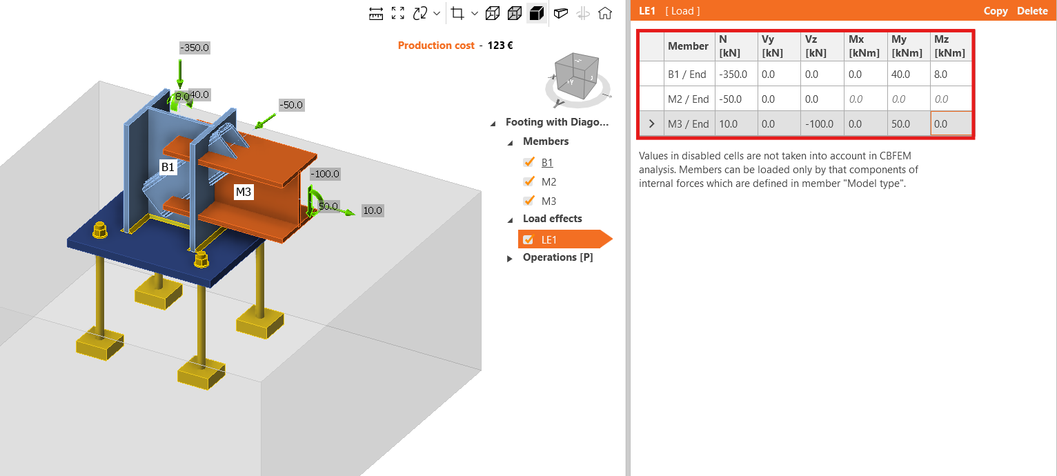
One load effect was automatically added. Input the values of internal forces into the chart. More load cases can be added.
4 Design
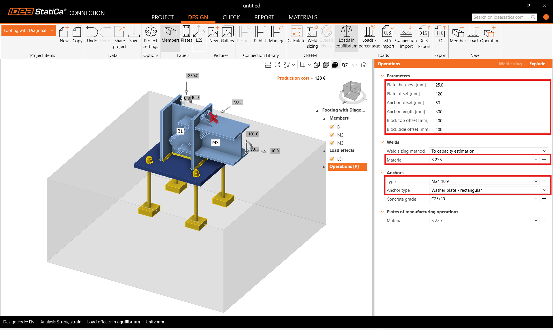
The manufacturing operation Base plate is defined in Parametric template, therefor you can modify its properties in the Operations tab directly.
You can also Explode the parametric template and use the manufacturing operation instead.
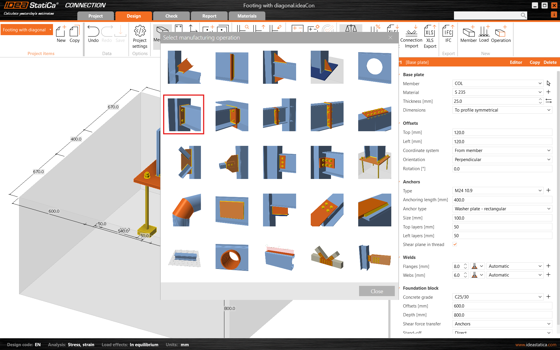
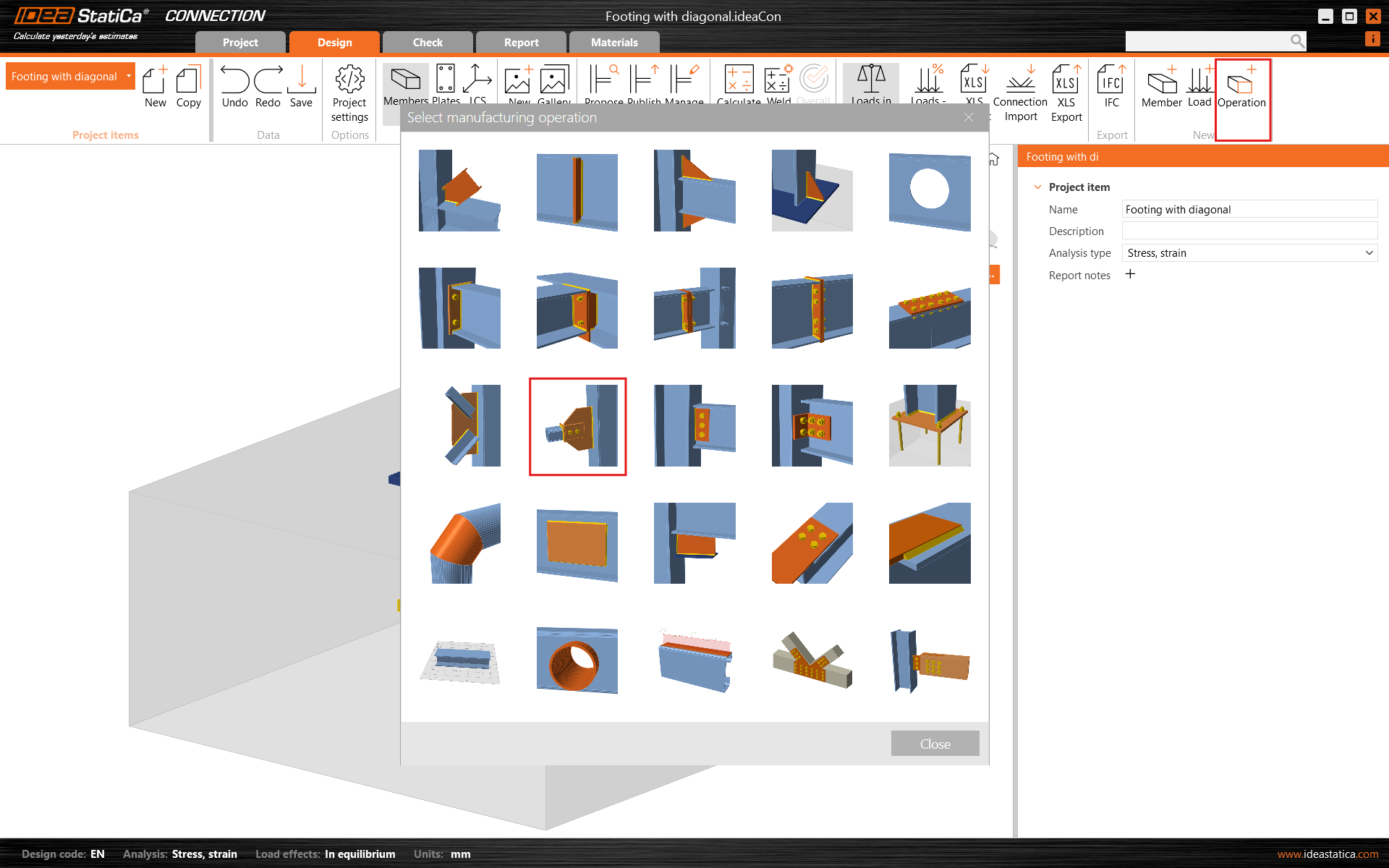
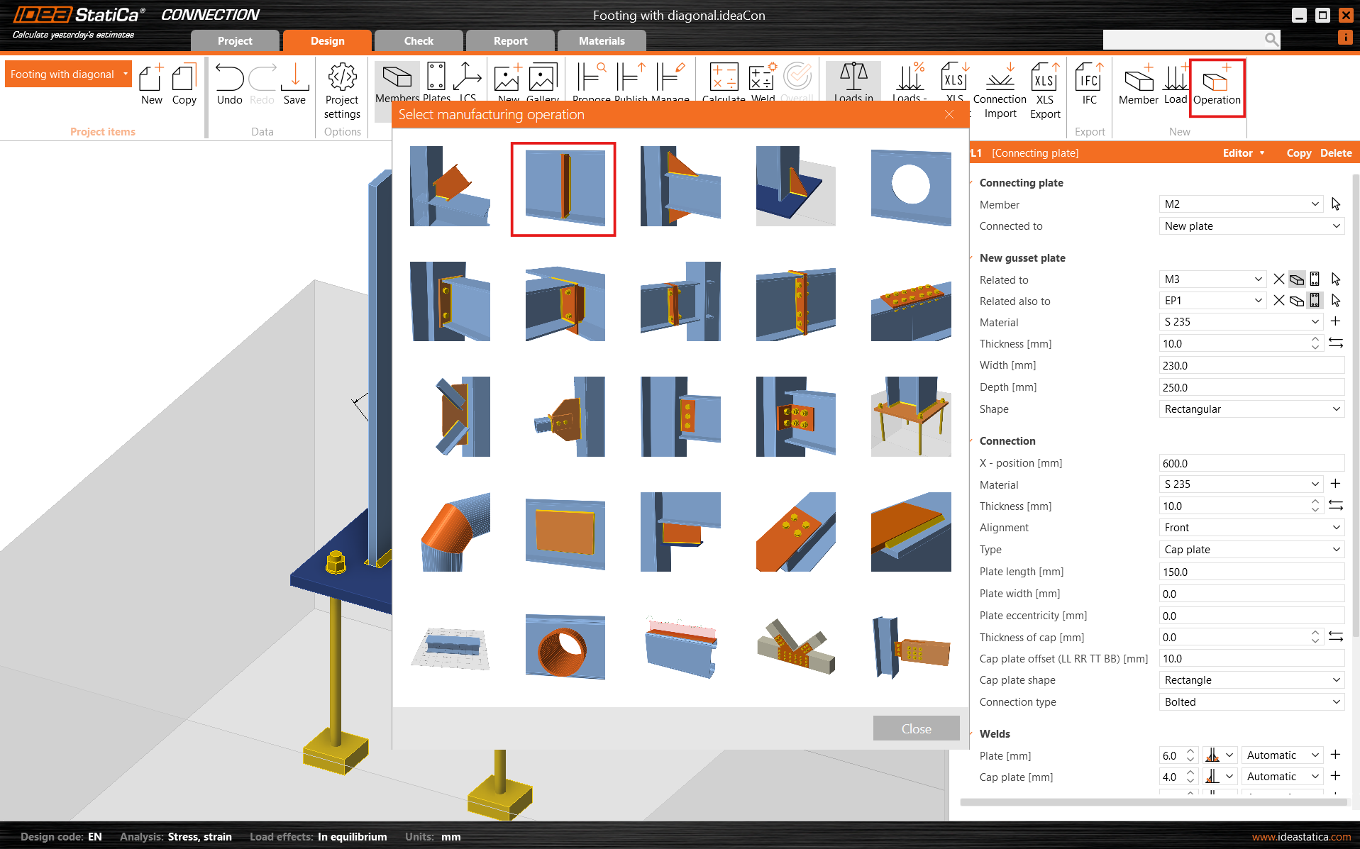
Go on and add another manufacturing operation and select the End Plate.
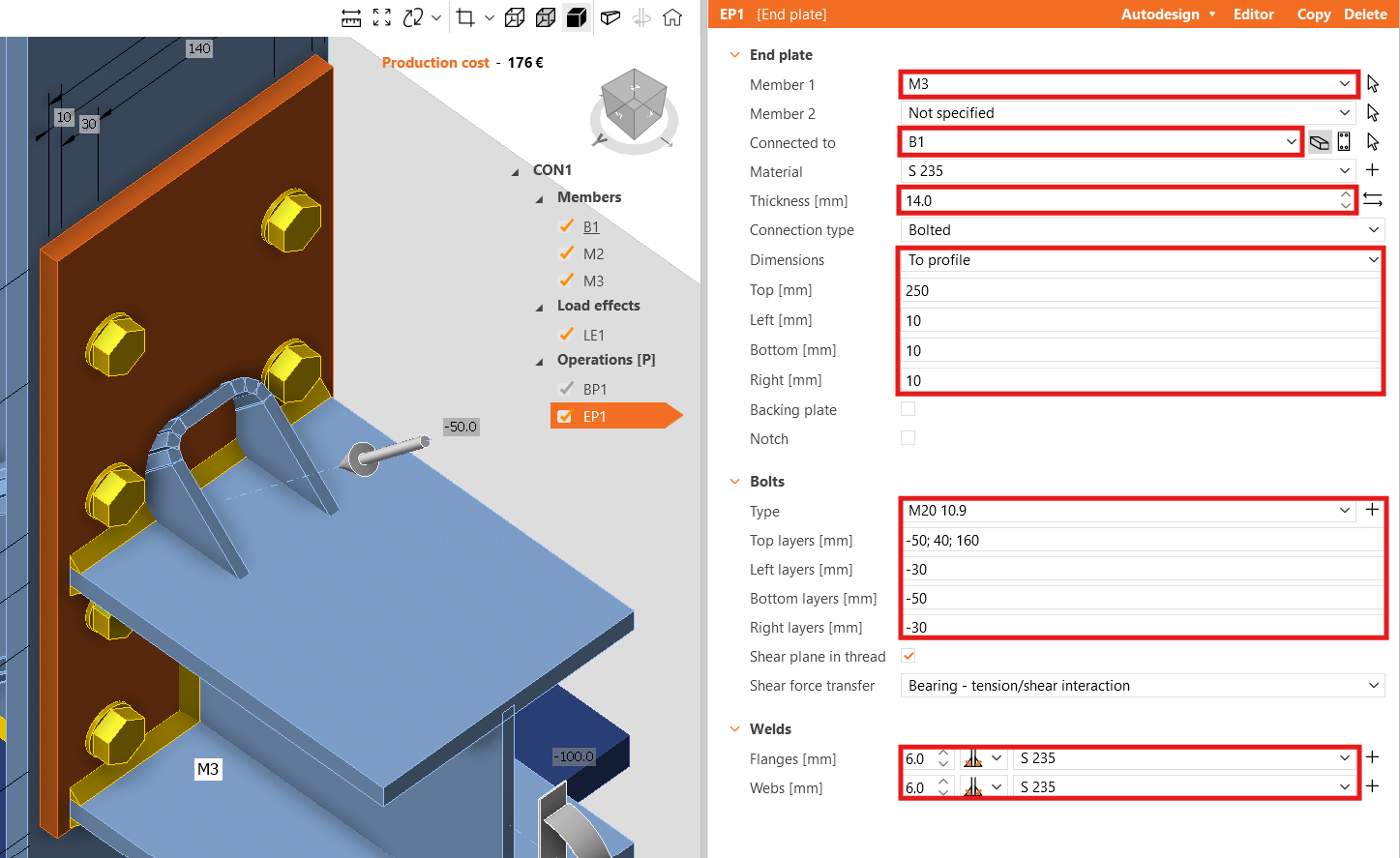
Modify the properties of the operation EP1.
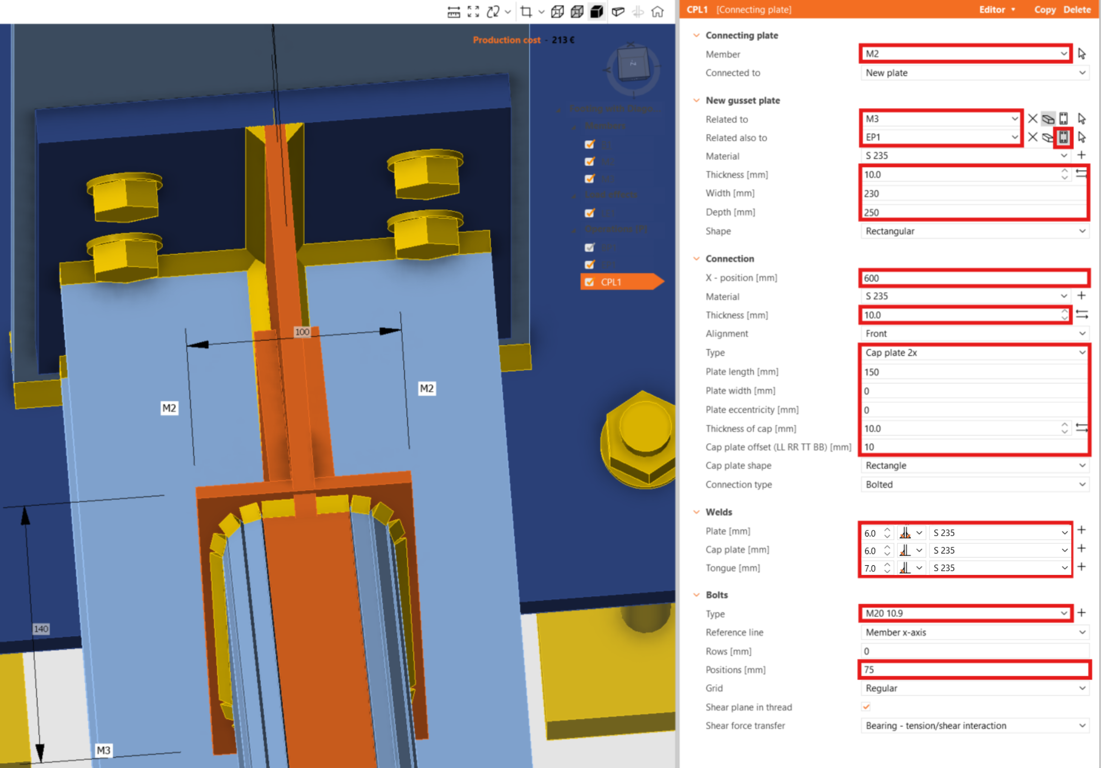
Now, add the Connecting Plate.
And redefine its properties.
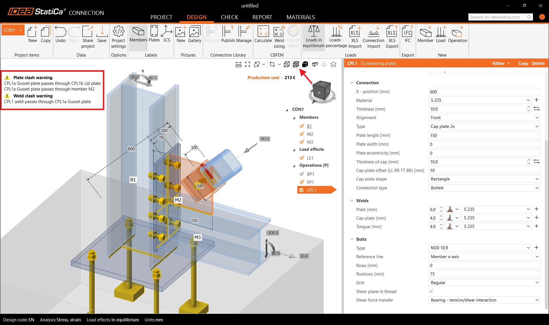
In the top left corner, you can see warning messages regarding the plates and weld clashes. Moreover, when you turn on the Transparent visualization mode, the area of the clashes is highlighted in the 3D graphic window.
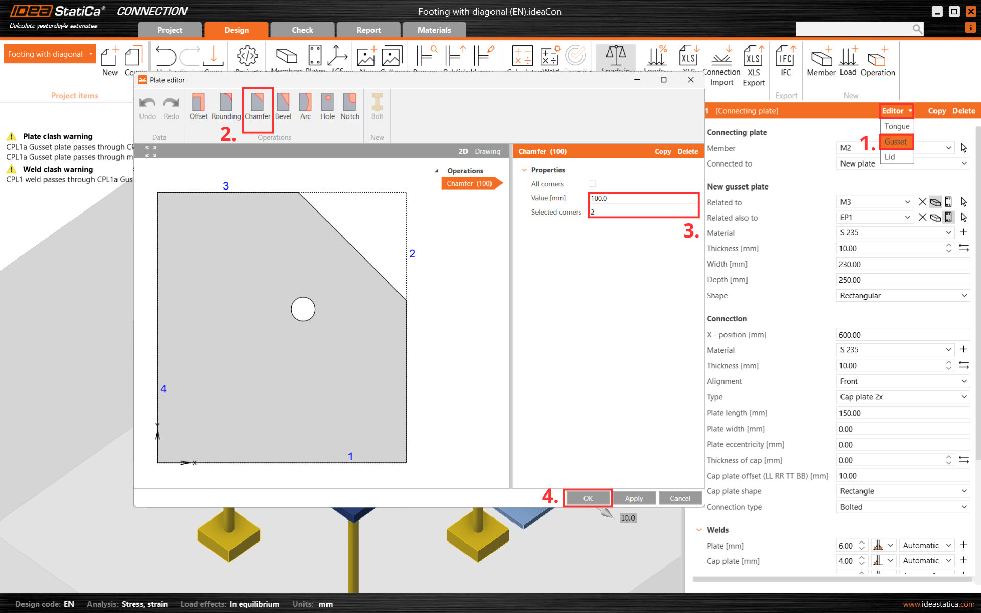
To get rid of the plates and weld clashes, cut one corner of the connecting plate CPL1. For this, go to the Editor - Gusset plate or use right-click on the gusset plate and create a Chamfer at corner number 2.
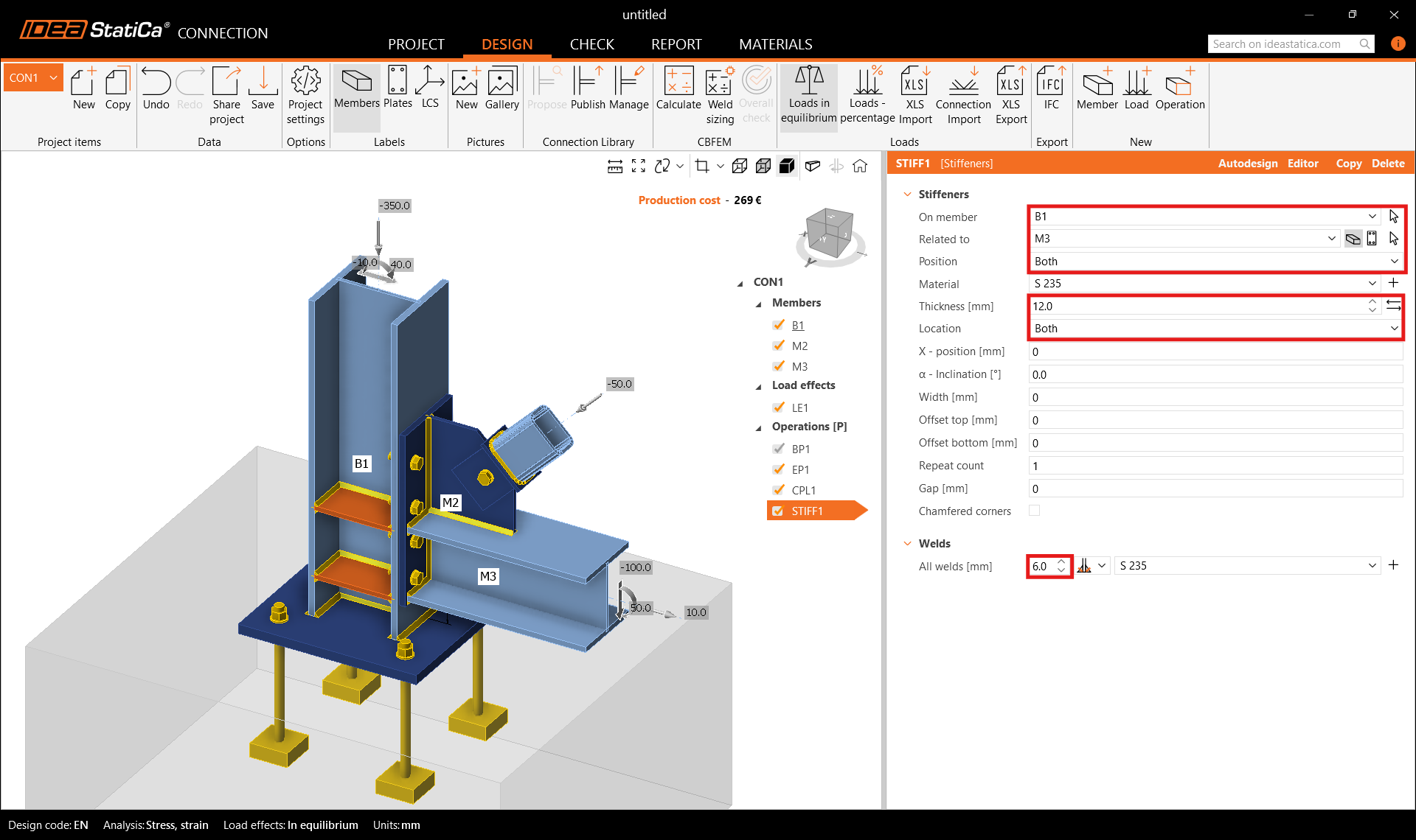
Finish the design with the operation Stiffener.
And set the correct properties of STIFF1.
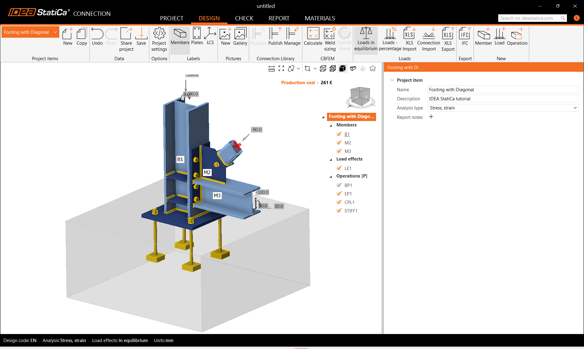
Let’s check the final design of the joint.
5 Check
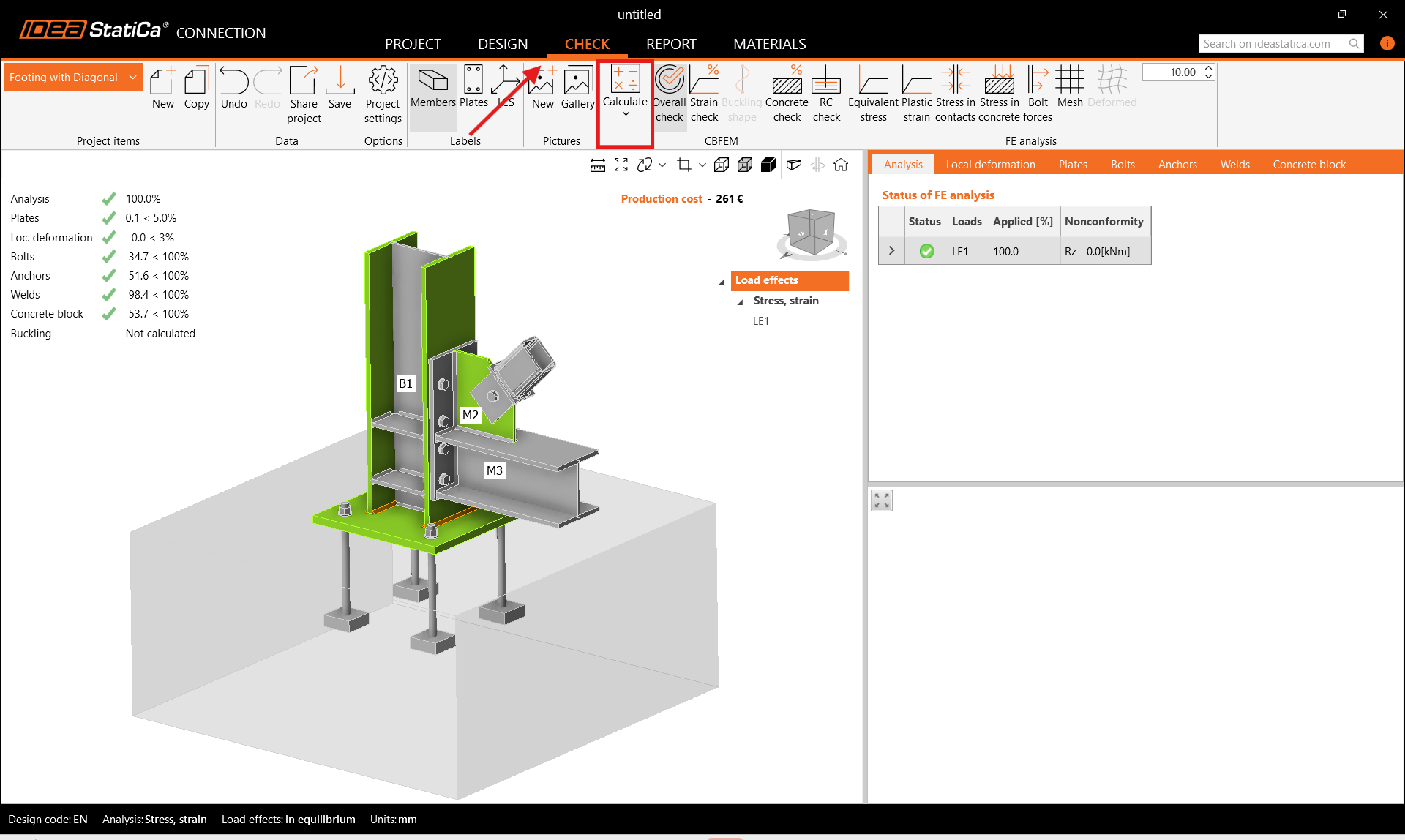
Start the analysis by clicking Calculate in the ribbon. The analysis model is automatically generated, the calculation based on CBFEM is performed, and we can see the Overall check displayed together with the basic values of check results.
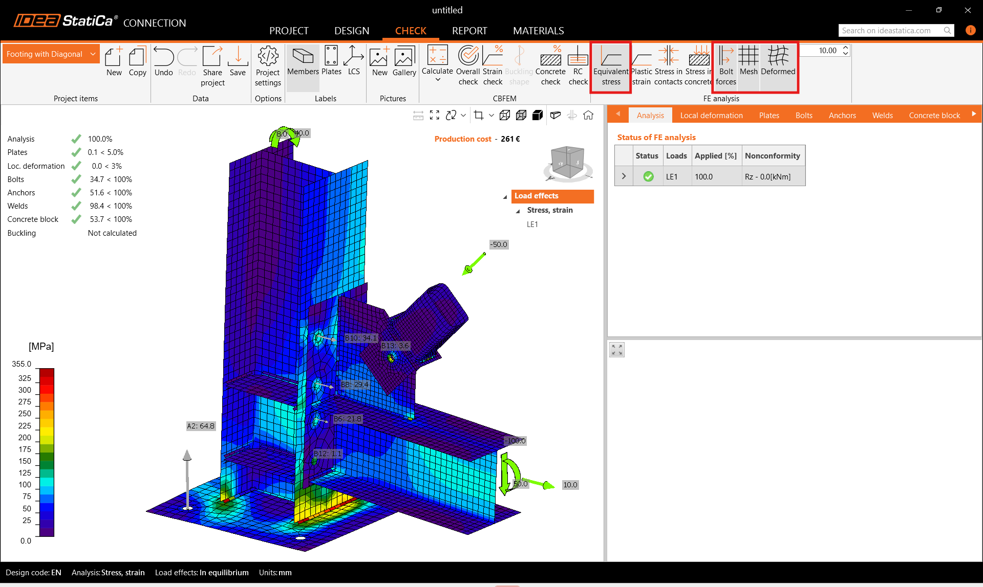
Go to the Check in the top ribbon, and activate Equivalent stress, Bolt forces, Mesh, and Deformed shape of the structure to get a full picture of the behavior of the joint.
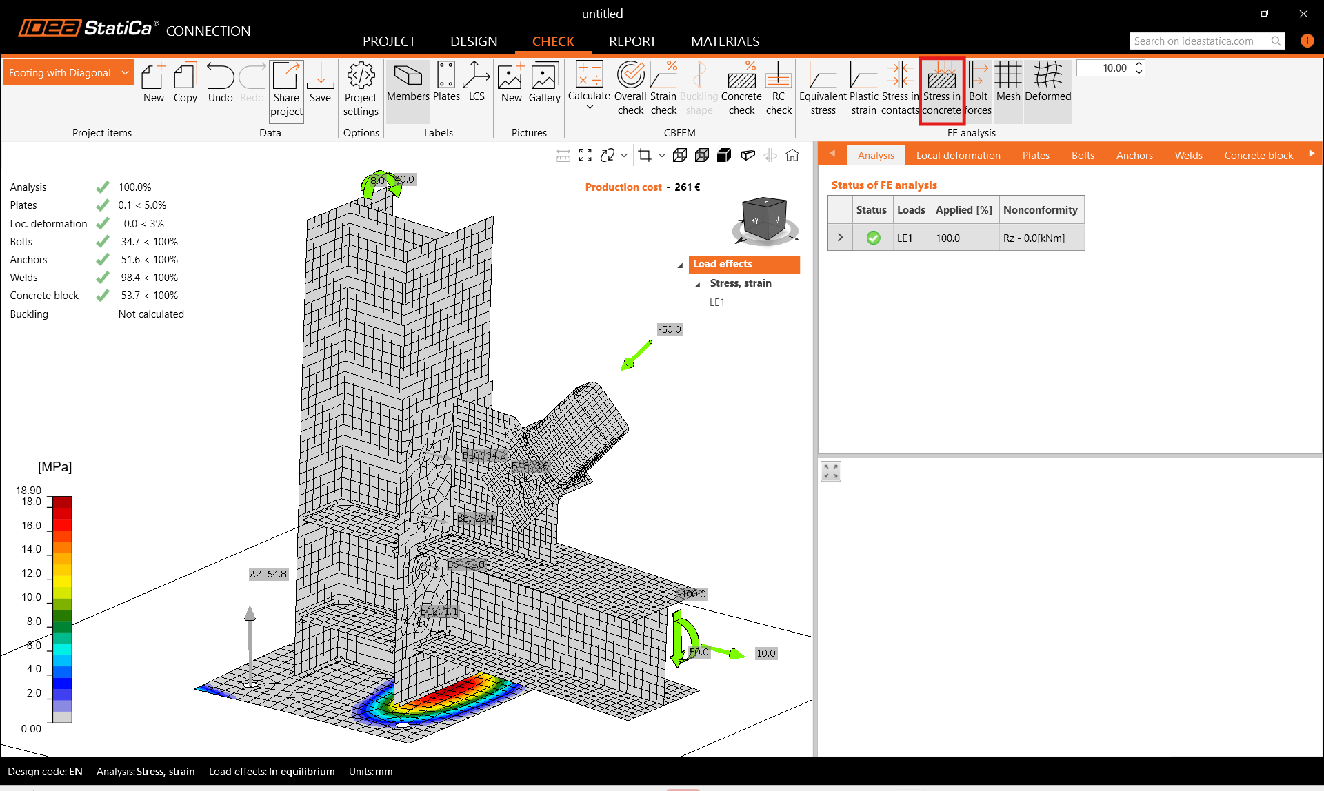
Furthermore, activate Stress in concrete from the top ribbon. Open the tab Concrete block to see the detailed results for this item.
6 Report
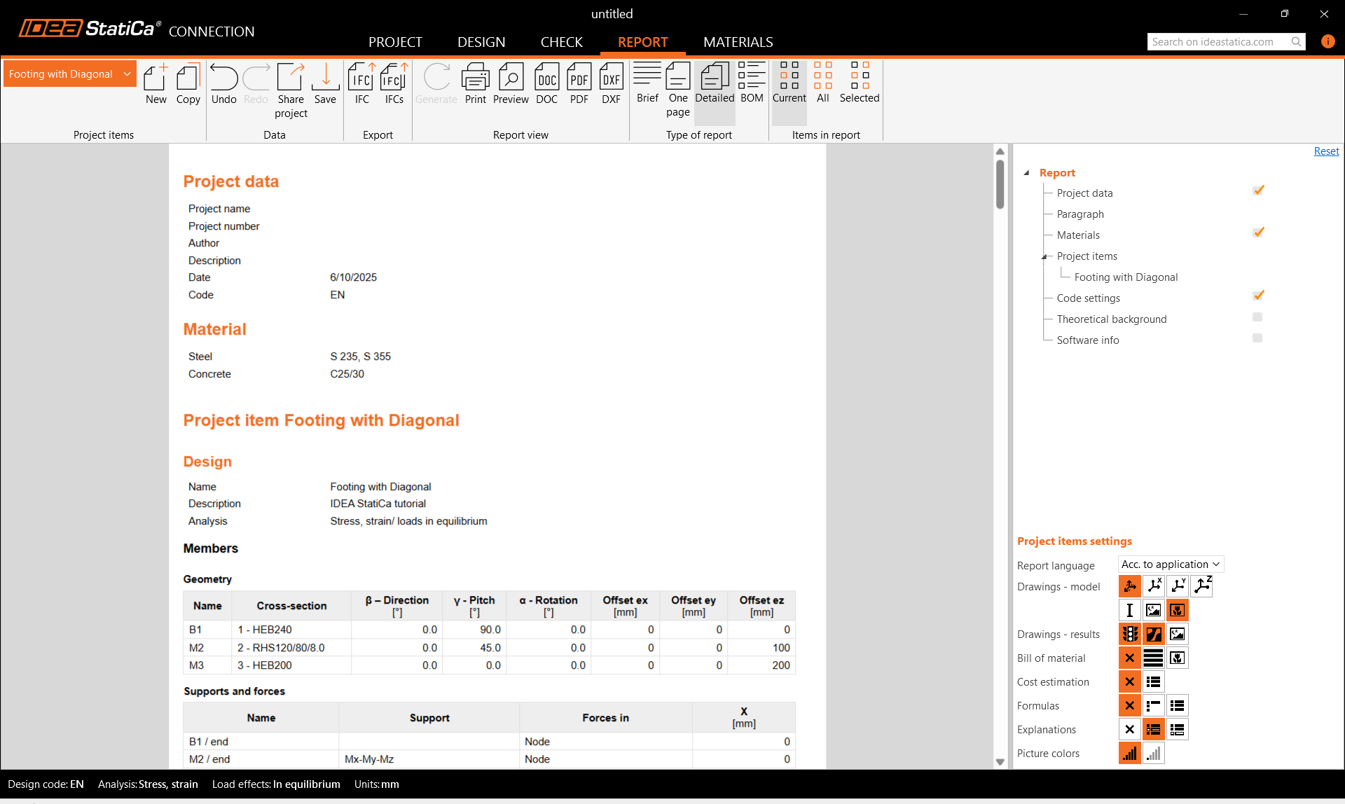
At last, go to the tab Report. IDEA StatiCa offers a fully customizable report to print out or save in an editable format.
You have designed, optimized, and code-checked a structural steel joint according to Eurocode (EN).